Page is loading ...

PRODUCT INFORMATION
REFLEX ARRAY
THE PHOTOELECTRIC SENSOR WITH THE 2D LIGHT ARRAY:
MULTIFACETED AND ECONOMICAL
MultiTask photoelectric sensors

REFLEX ARRAY | SICK 8013600/2019-02-26
Subject to change without notice
2
RAY10
RAY10
Figure MDO Sensing range Connection Smart sensor Switching output
RAY10
5 mm (0.20 inch) 1.5 m (59 inch)/P250F
• Cable, 4-wire
• Cable with M8 male
connector, 4-pin
• Cable with M12 male
connector, 4-pin
• Yes, IO -Link
• No
Push-pull (PNP/NPN)
RAY26
3 mm (0.12 inch) 2 m (78.74 inch)/PL80A
• 12 male connector,
4-pin
• Cable with M12 male
connector, 4-pin
• Cable, 4-pin
• Yes, IO -Link Push-pull (PNP/NPN)
5 mm (0.20 inch) 3 m (118 inch)/PL80A
10 mm (0.39 inch) 4.5 m (177 inch)/PL80A
Type overview
RELIABLE DETECTION, THANKS TO A 2D LIGHT ARRAY
36 mm (1.42 inch)
25 mm (0.98 inch)
P250F, 5308843
Detection height
(height of the light array)
The minimum detectable object
(MDO), regardless of the position
within the light array
≥ 5 mm
(0.20 inch)
38 mm (1.50 inch) Sensing range, minimum distance between the sensor and the reector: 300 mm

REFLEX ARRAY | SICK8013600/2019-02-26
Subject to change without notice
3
RAY26
RAY26
RAY10 and RAY26: Your benets
Reduces the overall costs for detection by up to 50% compared to other solutions
PinPoint LED enables great visibility of the light array and easy and fast optical
alignment of the photoelectric sensor
Continuous threshold adaptation (AutoAdapt) reduces downtimes
Smart sensors, including IO-Link as part of the Reex Array, accelerate machine
sequences, make them more efcient and transparent, and offer predictive
maintenance. This makes these products pioneers for Industry 4.0 applications.
53 mm (2.09 inch) Sensing range – no minimum distance required between the sensor and the reector
83 mm (3.27 inch)
55 mm (2.17 inch)
PL80A, 1003865
Detection height
(height of the light array)
The minimum detectable object
(MDO), regardless of the position
within the light array
≥ 3 mm
(0.12 inch)
≥ 5 mm
(0.20 inch)
≥ 10 mm
(0.39 inch)

REFLEX ARRAY | SICK 8013600/2019-02-26
Subject to change without notice
4
RAY10 and RAY26 FEATURES
CLEVER COMMISSIONING WITH IO-LINK
Easy and fast alignment thanks to PinPoint LED
Thanks to PinPoint LED, the light array of the Reex Array MultiTask photoelectric sensor is highly visible. After aligning the
photoelectric sensor, all that is required is to teach in the sensor, and then it is ready for detection.
RAY10 RAY26
Predictive maintenance
During operation, blue LEDs indicate the degree of contamination of the sensor and reector. IO-Link enables corresponding
data transfer to the PLC. This ensures that maintenance or cleaning of the device is scheduled in a timely manner. This prevents
unwanted downtimes.
BluePilot: The shorter the distance of the blue LEDs from each other, the higher the degree of contamination is (e.g., RAY10)
Conveyor belt blanking (only for RAY26P-xxxxx3)
Conveyor belt blanking enables gradual deactivation of the detection zone (A) right above the conveyor belt. This suppresses
the interference of the conveyor belt that causes the sensor to switch during system operation. Conveyor belt blanking is
congured via IO-Link.
RAY26
A
Conveyor belt

REFLEX ARRAY | SICK8013600/2019-02-26
Subject to change without notice
5
APPLICATIONS RAY10 and RAY26
... perforated objects
... transparent objects, such as glass bottles
RELIABLE DETECTION OF ...
... unevenly formed and shiny objects ... objects that have different heights
... at objects, such as polybags

REFLEX ARRAY | SICK 8013600/2019-02-26
Subject to change without notice
6
RAY10 and RAY26
11011001001
01101011010
11011001001
01101011010
Smart Tasks
From raw signals to customized
information
In these times of “big data”, it is important not to lose
sight of the big picture. For that reason, Smart Tasks
processes the diverse Smart Sensor signals for detec-
tion and measurement, linking them to signals from an
external sensor if necessary. Only the process informa-
tion that is actually necessary is generated. Coordinated
with the corresponding task in the system. This saves
time during data evaluation in the control, accelerates
machine processes, and makes high-performance,
cost-intensive additional hardware unnecessary.
Find out more: www.sick.com/smart-sensors
Diagnostics
Highest availability levels thanks
to predictive maintenance
With the diagnostics functions, you always know the
condition of your process and every single sensor. They
comprise automated sensor self-monitoring or process
parameter monitoring for preventative device and
system maintenance. Smart Sensors will even send a
notication independently if safe operation is at risk.
Thanks to predictive maintenance, exible, needs-based
maintenance schedules can be created, helping reduce
service costs. If problems should arise, however, the
cause can be easily determined thanks to comprehen-
sive visualization options, avoiding system downtimes.
Find out more: www.sick.com/smart-sensors
Enhanced Sensing and Efcient Communication
The best sensor performance, exibility, and transparency
The highest possible level of stability during object detection and recording of measured values is the basis for every Smart
Sensor. Benet from our experience spanning over 70 years in the development and application of groundbreaking sensor
technology. With superordinate control systems, our Smart Sensors communicate via IO-Link: This stable communication
channel which is used across the globe for sensors and actuators at eld level offers many practical advantages in day-to-
day industrial operation.
Find out more: www.sick.com/smart-sensors
SMART SENSORS FOR EFFICIENT MACHINE
COMMUNICATION
Networked production and control processes in complex machine environments
determine the industrial future and make Industry 4.0 possible in the rst place.
Smart Sensors already support dynamic, real-time-optimized, and self-organized
industry processes. They record real operational statuses, turn these into digital
data, and share them automatically with the process controller.

REFLEX ARRAY | SICK8013600/2019-02-26
Subject to change without notice
7
RAY10 and RAY26
SMART TASKS
Basic logic:
• Logic functions can be freely congured with a trigger
sensor
• Delays for switching signals can be freely congured
• Signal inversion
Time measurement and debouncing:
• Time measurement between the detection edges
• Switching signals are output when freely congured
timing values are reached, e.g., if objects that are
too short or too long have been detected
• Delays for switching signals can be freely congured
• Signal inversion
• Available on request
Counter and debouncing:
• Counting and evaluation of detection signals
• Switching signals are output when freely congured
counter values are reached
• Switching signal generated every x counter pulses
• Manual and automated counter reset
• Delays for switching signals can be freely congured
• Signal inversion
• Available on request

REFLEX ARRAY | SICK 8013600/2019-02-26
Subject to change without notice
8
RAY10 MULTITASK PHOTOELECTRIC SENSORS
Product description
The Reex Array in combination with
a reector detects the leading edge of
small, at, transparent, or uneven ob-
jects within its light band, regardless of
position. Perforated objects are reliably
detected without multiple signals. This
considerably reduces allover costs and
speeds up commissioning. The Reex
Array therefore offers major cost bene-
ts over conventional solutions, which
use several individual photoelectric
sensors or a small light grid. The RAY10
is the ideal choice for applications such
as the detection of polybags. As an
extra advantage, this exceptional per-
formance is packed into an extremely
compact housing which can be mounted
directly on the conveyor and aligned in
no time.
At a glance
• Small housing for easy integration
into a conveyor
• Detects objects ≥5 mm within a
25 mm light array
• Sensing range for detection up to
max. 1.5 m depending
• Predictive maintenance is given with
an optical feedback on the devices
and via IO-Link depending on type
• Smart Sensor: Enhanced Sensing,
IO-Link, Diagnose, Smart Tasks de-
pending on type
Your benets
• Reduces the allover costs of detec-
tion required by up to 50% compared
to other solutions
• Detects objects ≥5 mm within a
25 mm light array of 25 mm regard-
less of position
• Increases productivity due to reliable
detection independent of the objects,
characterized by shiny, irregular,
high-contrast, different colors
• Increases productivity due to reliable
detection without any interruption of
objects with perforated structure or
inhomogeneity
• Enables simple an quick commission-
ing thanks PinPoint LED and optical
alignment aid
• Predictive maintenance due to Auto-
Adapt, optical feedback and alarm
output
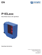
Reex Array
MULTITASK PHOTOELECTRIC SENSORS
RAY10
Subject to change without notice
A
.
THE PHOTOELECTRIC SENSOR WITH THE LIGHT
ARRAY: VERSATILE AND COST-EFFECTIVE
Additional information
Detailed technical data . . . . . . . . . . . .9
Ordering information . . . . . . . . . . . . 11
Dimensional drawing . . . . . . . . . . . . 12
Connection diagram. . . . . . . . . . . . . 12
Light spot size . . . . . . . . . . . . . . . . . . 12
- www.sick.com/RAY10
For more information, simply enter the link or scan the QR code and get direct access to
technical data, CAD design models, operating instructions, software, application examples, and
much more.
A
B
C
D
E
F
H
I
J
K
L
M
N
O
P
Q
R
S
T

REFLEX ARRAY | SICK8013600/2019-02-26
Subject to change without notice
9
MULTITASK PHOTOELECTRIC SENSORS RAY10
Detailed technical data
Features
Sensor principle
Photoelectric retro-reective sensor
Detection principle
Dual lens
Dimensions (W x H x D)
21.5 mm x 36 mm x 37.7 mm
Housing design (light emission)
Rectangular
Minimum object size
5 mm, position-independent detection within the light array
Detection height
25 mm
Sensing range max.
1)
0 m ... 1.5 m
Distance of the sensor to reector
1)
0.3 m ... 1.5 m
Type of light
Visible red light
Light source
2)
PinPoint LED
Light spot size (distance)
37 mm x 12 mm (1 m)
Wave length
635 nm
Adjustment
Potentiometer
IO-Link
(depending on type)
Pin 2 conguration
External Input (test), Teach-in, switching signal
AutoAdapt
l
Special applications
Detecting transparent objects, Detecting perforated objects, Detecting uneven, shiny ob-
jects, Detecting objects with position tolerances
1)
Reector P250F.
2)
Average service life: 100,000 h at T
U
= +25 °C.
Mechanics/electronics
Supply voltage
1)
10 V DC ... 30 V DC
Ripple
≤ 5 V
pp
Power consumption
2)
30 mA
Switching output
PUSH/PULL, PNP, NPN
Switching output or IO-Link mode
Output function
Factory setting: Pin 2 (MF): NPN normally closed (light switching), PNP normally open (dark
switching), Pin 4 (QL1/C): NPN normally open (dark switching), PNP normally closed (light
switching), IO-Link
Switching mode
Light/dark switching
Switching mode selector
Via IO-Link
Signal voltage PNP HIGH/LOW
Approx. V
S
– 2.5 V / 0 V
Signal voltage NPN HIGH/LOW
Approx. VS / < 2.5 V
Output current I
max.
≤ 100 mA
Response time
3)
≤ 0.5 ms
Switching frequency
4)
± 1,000 Hz
Connection type
Cable, 2 m
5)
Cable with male connector, M12, 300 mm
5)
Cable with male connector, M12, 1 m
5)
Cable with male connector, M8, 300 mm
5)
Cable with male connector, M8, 1 m
5)
(depending on type)
Circuit protection
A
6)
, B
7)
, C
8)
, D
9)
Protection class
III
Weight
130 g
Housing material
Plastic, ABS
A
B
C
D
E
F
H
I
J
K
L
M
N
O
P
Q
R
S
T

REFLEX ARRAY | SICK 8013600/2019-02-26
Subject to change without notice
10
RAY10 MULTITASK PHOTOELECTRIC SENSORS
Optics material
Plastic, PMMA
Enclosure rating
IP67
Ambient operating temperature
10)
–40 °C ... +60 °C
Ambient storage temperature
–40 °C ... +70 °C
1)
Limit values.
2)
Without load.
3)
Signal transit time with resistive load in switching mode. Different values possible in COM2 mode.
4)
With light/dark ratio 1:1 in switching mode. Different values possible in IO-Link mode.
5)
Do not bend below 0 °C.
6)
A = V
S
connections reverse-polarity protected.
7)
B = inputs and output reverse-polarity protected.
8)
C = interference suppression.
9)
D = outputs overcurrent and short-circuit protected.
10)
Avoid condensation on the front screen of the sensor and on the reector.
Smart Task
Smart Task name
Base logics
Logic function
Direct
AND
OR
Window
Hysteresis
Timer function
Deactivated
On delay
Off delay
ON and OFF delay
Impulse (one shot)
Inverter
Yes
Switching frequency
SIO Direct: 500 Hz
1)
SIO Logic: 500 Hz
2)
IOL: 217 Hz
3)
Response time
SIO Direct: 1 ms
1)
SIO Logic: 1 ms
2)
IOL: 2,3 ms
3)
Repeat accuracy
SIO Direct: 1 ms
1)
SIO Logic: 1 ms
2)
IOL: 2,3 ms
3)
Switching signal Q
L1
Switching output
Switching signal Q
L2
Switching output
1)
SIO Direct: sensor operation in standard I/O mode without IO-Link communication and without using internal sensor logic or time parameters
(set to “direct”/“deactivated”).
2)
SIO Logic: Sensor operation in standard I/O mode without IO-Link communication. Sensor-internal logic or timing parameters plus Automation Functions used.
3)
IOL: Sensor operation with full IO-Link communication and usage of logic, timing and Automation Function parameters.
Communication interface
Communication interface
IO-Link V1.1
Mode
COM2 (38,4 kBaud)
Cycle time
2.3 ms
Process data length
16 Bit
Process data structure
Bit 0 = switching signal Q
L1
Bit 1 = switching signal Q
L2
Bit 2 ... 15 = empty
VendorID
26
A
B
C
D
E
F
H
I
J
K
L
M
N
O
P
Q
R
S
T

REFLEX ARRAY | SICK8013600/2019-02-26
Subject to change without notice
11
MULTITASK PHOTOELECTRIC SENSORS RAY10
Ordering information
• Detection height: 25 mm
• Detection principle: Dual lens
• Switching output: PUSH/PULL, PNP, NPN
• Switching mode: Light/dark switching
• Minimum object size: ≥ 5 mm
Sensing range
max.
1)
Adjustment Communica-
tion interface
Connection DeviceID Connection
diagram
Type Part no.
0 m ... 1.5 m
Potentiometer -
Cable with M12
male con-
nector, 4-pin
300 mm PVC
– cd-083 RAY10-AB4CBL 1091724
Cable with M12
male connec-
tor, 4-pin 1 m
PVC
– cd-083 RAY10-AB4EBL 1093749
Cable with
ying leads,
4-wire 2 m PVC
– cd-094 RAY10-AB1GBL 10 93745
Cable with
male connector
M8, 4-pin, snap
300 mm PVC
– cd-083 RAY10-AB5CBL 10 93747
Cable with
male connector
M8, 4-pin, snap
1 m PVC
– cd-083 RAY10-AB5EBL 10 93746
Potentiometer
IO-Link
IO-Link
Cable with M12
male con-
nector, 4-pin
300 mm PVC
8389085,
0x8001DD
cd-390 RAY10-AB4CBLA00 1096100
Cable with M12
male connec-
tor, 4-pin 1 m
PVC
8389085,
0x8001DD
cd-390 RAY10-AB4EBLA00 1096103
Cable, 4-wire
2 m PVC
8389085,
0x8001DD
cd-389 RAY10-AB1GBLA00 1095884
Cable with
male connector
M8, 4-pin, snap
300 mm PVC
8389085,
0x8001DD
cd-390 RAY10-AB5CBLA00 1096102
Cable with
male connector
M8, 4-pin, snap
1 m PVC
8389085,
0x8001DD
cd-390 RAY10-AB5EBLA00 1096101
1)
Reector P250F.
A
B
C
D
E
F
H
I
J
K
L
M
N
O
P
Q
R
S
T

REFLEX ARRAY | SICK 8013600/2019-02-26
Subject to change without notice
12
RAY10 MULTITASK PHOTOELECTRIC SENSORS
Dimensional drawing (Dimensions in mm (inch))
21.5 (0.85)
8 (0.31)
26.1 (1.03)
18 (0.71)
36 (1.42)
3.5
(0.14)
29 (1.14)
12.4
(0.49)
5
(0.2)
8 (0.31)
Ø 3.5
(0.14)
37.7 (1.48)
3.8 (0.15)
12
3
4
5
6
8
7
1 Potentiometer / LED indicator green
2 Potentiometer / LED indicator orange
3 BluePilot blue: signal strength light bar during teach process / AutoAdapt indicator during run
4 Mounting hole M3 (Ø 3.1 mm)
5 Mounting hole M3 (Ø 3.1 mm)
6 Optical axis
7 Optical axis
8 Optical axis
Connection diagram
Cd-094
+ (L+)
Q
- (M)
BN
WH
BU
Q
BK
Cd-389
Q
L1
/C
+ (L+)
– (M)
MF
BN
WH
BK
BU
Cd-083
+ (L+)
Q
- (M)
BN
WH
BU
BK
1
2
3
Q
4
Cd-390
Q
L1
/C
4
+ (L+)
– (M)
MF
BN
WH
BK
BU
1
2
3
Light spot size
0
0
0.75
(2.46)
0.5
(1.64)
0.25
(0.82)
1.5
(4.92)
1
(3.28)
1.25
(4.10)
–10
(–0.39)
–20
(–0.79)
10
(0.39)
20
(0.79)
Distance in m (feet)
mm (inch)
–30
(–1.18)
30
(1.18)
A
B
C
D
E
F
H
I
J
K
L
M
N
O
P
Q
R
S
T

REFLEX ARRAY | SICK8013600/2019-02-26
Subject to change without notice
13
MULTITASK PHOTOELECTRIC SENSORS RAY10
A
B
C
D
E
F
H
I
J
K
L
M
N
O
P
Q
R
S
T

REFLEX ARRAY | SICK 8013600/2019-02-26
Subject to change without notice
14
RAY26 MULTITASK PHOTOELECTRIC SENSORS
Product description
The Reex Array in combination with
a reector detects the leading edge of
small, at, transparent, or uneven ob-
jects within its light band, regardless of
position. Perforated objects are reliably
detected without multiple signals. This
considerably reduces allover costs and
speeds up commissioning. The Reex
Array therefore offers major cost bene-
ts over conventional solutions, which
use several individual photoelectric
sensors or a small light grid.
At a glance
• RAY26 offers three different variants
to detect objects ≥ 3 mm, ≥ 5 mm or
≥ 10 mm always within a 55 mm light
array
• Sensing range for detection from 0 m
to max. 4.5 m depending on the type
• Predictive maintenance is given with
an optical feedback on the devices
and via IO-Link
• RAY26 has additionally a stepwise
suppression for vertical uctuation of
the conveyor belt depending on the
type
• Smart Sensor: Enhanced Sensing,
IO-Link, Diagnose, Smart Tasks
Your benets
• Reduces the allover costs of detec-
tion required by up to 50% compared
to other solutions
• Detects objects ≥ 3 mm, ≥ 5 mm or ≥
10 mm within a light array of 55 mm,
regardless of position
• Increases productivity due to reliable
detection independent of the objects,
characterized by shiny, irregular,
high-contrast, different colors
• Increases productivity due to reliable
detection without any interruption of
objects with perforated structure or
inhomogeneity
• Enables simple an quick commission-
ing thanks PinPoint LED
• Predictive maintenance due to Auto-
Adapt, optical feedback and alarm
output
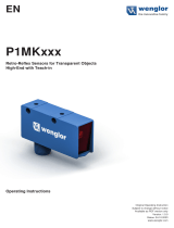
RAY26
THE PHOTOELECTRIC SENSOR WITH THE LIGHT
ARRAY: MULTIFACETED AND ECONOMICAL
Additional information
Detailed technical data . . . . . . . . . . 15
Ordering information . . . . . . . . . . . . .17
Dimensional drawing . . . . . . . . . . . . 18
Connection diagram. . . . . . . . . . . . . 18
Light spot size . . . . . . . . . . . . . . . . . . 18
- www.sick.com/RAY26
For more information, simply enter the link or scan the QR code and get direct access to
technical data, CAD design models, operating instructions, software, application examples, and
much more.
A
B
C
D
E
F
H
I
J
K
L
M
N
O
P
Q
R
S
T

REFLEX ARRAY | SICK8013600/2019-02-26
Subject to change without notice
15
MULTITASK PHOTOELECTRIC SENSORS RAY26
Detailed technical data
Features
Sensor principle
Photoelectric retro-reective sensor
Detection principle
Autocollimation
Dimensions (W x H x D)
24.6 mm x 82.5 mm x 53.3 mm
Housing design (light emission)
Rectangular
Minimum object size
3 mm, position-independent detection within the light array
5 mm, position-independent detection within the light array
10 mm, position-independent detection within the light array
(depending on type)
Detection height
55 mm
Sensing range max.
0 m ... 2 m
1)
2)
0 m ... 3 m
1)
3)
0 m ... 4.5 m
1)
4)
(depending on type)
Distance of the sensor to reector
≥ 0 m
Type of light
Visible red light
Light source
5)
PinPoint LED
Light spot size (distance)
55 mm x 9 mm (1 m)
Wave length
635 nm
Adjustment
BluePilot: Teach-in
IO-Link
Pin 2 conguration
External Input (test), Teach-in, switching signal
AutoAdapt
l
Special applications
Detecting objects with position tolerances, Detecting perforated objects, Detecting uneven,
shiny objects, Detecting transparent objects
1)
Reector PL80A.
2)
At minimum object size 3 mm.
3)
At minimum object size 5 mm.
4)
At minimum object size 10 mm.
5)
Average service life: 100,000 h at T
U
= +25 °C.
Mechanics/electronics
Supply voltage
1)
10 V DC ... 30 V DC
Ripple
≤ 5 V
pp
Power consumption
25 mA
2)
40 mA
3)
Switching output
PUSH/PULL, PNP, NPN
Switching output or IO-Link mode
Output function
Factory setting: Pin 2 (MF): NPN normally closed (light switching), PNP normally open (dark
switching), Pin 4 (QL1/C): NPN normally open (dark switching), PNP normally closed (light
switching), IO-Link
Switching mode
Light/dark switching
Switching mode selector
Via IO-Link
Signal voltage PNP HIGH/LOW
Approx. V
S
– 2.5 V / 0 V
Signal voltage NPN HIGH/LOW
Approx. VS / < 2.5 V
Output current I
max.
≤ 100 mA
Response time
4)
≤ 3 ms
Switching frequency
5)
170 Hz
A
B
C
D
E
F
H
I
J
K
L
M
N
O
P
Q
R
S
T

REFLEX ARRAY | SICK 8013600/2019-02-26
Subject to change without notice
16
RAY26 MULTITASK PHOTOELECTRIC SENSORS
Connection type
Cable with male connector, M12, 270 mm
6)
Cable, 2 m
6)
Male connector, M12
(depending on type)
Circuit protection
A
7)
, B
8)
, C
9)
, D
10)
Protection class
III
Weight
Cable with M12 male connector, 4-pin 100 g
Cable, 4-wire 130 g
Male connector M12, 4-pin 80 g
Housing material
Plastic, VISTAL
®
Optics material
Plastic, PMMA
Enclosure rating
IP66, IP67
Ambient operating temperature
11)
12)
–40 °C ... +60 °C
Ambient storage temperature
–40 °C ... +75 °C
1)
Limit values.
2)
16 V DC ... 30 V DC, without load.
3)
10 V DC ... 16 V DC, without load.
4)
Signal transit time with resistive load in switching mode. Different values possible in COM2 mode.
5)
With light/dark ratio 1:1 in switching mode. Different values possible in IO-Link mode.
6)
Do not bend below 0 °C.
7)
A = V
S
connections reverse-polarity protected.
8)
B = inputs and output reverse-polarity protected.
9)
C = interference suppression.
10)
D = outputs overcurrent and short-circuit protected.
11)
Avoid condensation on the front screen of the sensor and on the reector.
12)
allowed temperature change after Teach +/- 20 K.
Smart Task
Smart Task name
Base logics
Logic function
Direct
AND
OR
Window
Hysteresis
Timer function
Deactivated
On delay
Off delay
ON and OFF delay
Impulse (one shot)
Inverter
Yes
Switching frequency
SIO Direct: 170 Hz
1)
SIO Logic: 170 Hz
2)
IOL: 170 Hz
3)
Response time
SIO Direct: 3 ms
1)
SIO Logic: 3 ms
2)
IOL: 3 ms
3)
Repeat accuracy
SIO Direct: 1,5 ms
1)
SIO Logic: 1,5 ms
2)
IOL: 1,5 ms
3)
Switching signal Q
L1
Switching output
Switching signal Q
L2
Switching output
1)
SIO Direct: sensor operation in standard I/O mode without IO-Link communication and without using internal sensor logic or time parameters
(set to “direct”/“deactivated”).
2)
SIO Logic: Sensor operation in standard I/O mode without IO-Link communication. Sensor-internal logic or timing parameters plus Automation Functions used.
3)
IOL: Sensor operation with full IO-Link communication and usage of logic, timing and Automation Function parameters.
A
B
C
D
E
F
H
I
J
K
L
M
N
O
P
Q
R
S
T

REFLEX ARRAY | SICK8013600/2019-02-26
Subject to change without notice
17
MULTITASK PHOTOELECTRIC SENSORS RAY26
Communication interface
Communication interface
IO-Link V1.1
Mode
COM2 (38,4 kBaud)
Cycle time
2.3 ms
Process data length
16 Bit
Process data structure
Bit 0 = switching signal Q
L1
Bit 1 = switching signal Q
L2
Bit 2 ... 15 = empty
VendorID
26
Ordering information
• Detection height: 55 mm
• Detection principle: autocollimation
• Switching output: PUSH/PULL, PNP, NPN
• Switching mode: Light/dark switching
• Adjustment: BluePilot: Teach-in, IO-Link
• Communication interface: IO-Link
Sensing range
max.
1)
Minimum object
size
Connection DeviceID Connection dia-
gram
Type Part no.
0 m ... 2 m
2)
0 m ... 3 m
3)
0 m ... 4.5 m
4)
≥ 3 mm
5)
≥ 5 mm
5)
≥ 10 mm
5)
Cable with M12
male connector,
4-pin 270 mm PVC
8389143,
0x800217
cd-390
RAY26P-
34162330A00
1221943
Cable, 4-wire 2 m
PVC
8389143,
0x800217
cd-389
RAY26P-
1H162330A00
1221945
Male connector
M12, 4-pin
8389143,
0x800217
cd-390
RAY26P-
24162330A00
1221060
0 m ... 3 m
3)
≥ 5 mm
Cable with M12
male connector,
4-pin 270 mm PVC
8389144,
0x800218
cd-390
RAY26P-
34162530A00
1221947
Cable, 4-wire 2 m
PVC
8389144,
0x800218
cd-389
RAY26P-
1H162530A00
1221948
Male connector
M12, 4-pin
8389144,
0x800218
cd-390
RAY26P-
24162530A00
1221946
0 m ... 4.5 m
4)
≥ 10 mm
Cable with M12
male connector,
4-pin 270 mm PVC
8389145,
0x800219
cd-390
RAY26P-
34162930A00
1221950
Cable, 4-wire 2 m
PVC
8389145,
0x800219
cd-389
RAY26P-
1H162930A00
1221951
Male connector
M12, 4-pin
8389145,
0x800219
cd-390
RAY26P-
24162930A00
1221949
1)
Reector PL80A.
2)
At minimum object size 3 mm.
3)
At minimum object size 5 mm.
4)
At minimum object size 10 mm.
5)
Adjustable via IO-Link incl. adjustable conveyor belt blanking.
A
B
C
D
E
F
H
I
J
K
L
M
N
O
P
Q
R
S
T

REFLEX ARRAY | SICK 8013600/2019-02-26
Subject to change without notice
18
RAY26 MULTITASK PHOTOELECTRIC SENSORS
Dimensional drawing (Dimensions in mm (inch))
RAY26, cable (with male connector)
1
24.6
(0.97)
8 (0.31)
6.9 (0.27)
Ø 12.8 (0.50)
55 (2.17)
37.9 (1.49)
9.4 (0.37)
7.2
(0.28)
3
2
2
7.1 (0.28)
8.1 (0.32)
10.8 (0.43)
25 (0.98)
38.9 (1.53)
6.4
(0.25)
48.1 (1.89)
40 (1.57)
44.2 (1.74)
10
(0.39)
Ø 5.2 (0.2)
82.2 (3.24)
70 (2.76)
Ø 5.2 (0.2)
8.1 (0.32)
76.5 (3.01)
82.5 (3.25)
53.4 (2.10)
7
465
21
(0.83)
1 Center of optical axis
2 Mounting hole, Ø 5.2 mm
3 Connection
4 BluePilot blue: AutoAdapt indicator during run mode
5 Teach-in button
6 LED indicator yellow: Status of received light beam
7 LED indicator green: Supply voltage active
RAY26, male connector
M12
1
3
2
2
7.1 (0.28)
8.1
(0.32)
10.8 (0.43)
25 (0.98)
38.9 (1.53)
6.3 (0.25)
48.1 (1.89)
40 (1.57)
44.2 (1.74)
19.7
(0.78)
Ø 5.2
(0.2)
24.6 (0.97)
8 (0.31)
6.9 (0.27)
82.2 (3.24)
70 (2.76)
Ø 5.2 (0.2)
17.1
(0.67)
7.9 (0.31)
76.5 (3.01)
82.5 (3.25)
55 (2.17)
37.9 (1.49)
9.4 (0.37)
53.3 (2.1)
63.9 (2.52)
21
(0.83)
7
465
1 Center of optical axis
2 Mounting hole, Ø 5.2 mm
3 Connection
4 BluePilot blue: AutoAdapt indicator during run mode
5 Teach-in button
6 LED indicator yellow: Status of received light beam
7 LED indicator green: Supply voltage active
Connection diagram
Cd-390
Q
L1
/C
4
+ (L+)
– (M)
MF
BN
WH
BK
BU
1
2
3
Cd-389
Q
L1
/C
+ (L+)
– (M)
MF
BN
WH
BK
BU
Light spot size
0
0
2
(6.56)
1
(3.28)
5
(16.40)
3
(9.84)
4
(13.12)
–10
(–0.39)
–20
(–0.79)
–40
(–1.56)
–30
(–1.18)
10
(0.39)
20
(0.79)
40
(1.56)
30
(1.18)
Distance in m (feet)
mm (inch)
A
B
C
D
E
F
H
I
J
K
L
M
N
O
P
Q
R
S
T

REFLEX ARRAY | SICK8013600/2019-02-26
Subject to change without notice
REFLEX ARRAY Accessories
19
Accessories
Mounting systems
Universal bar clamp systems
Figure Material Description Type Part no.
RAY10
P250F
RAY26
PL80A
Zinc plated steel (sheet), Zinc die
cast (clamping bracket)
Plate N08 for universal clamp
bracket
BEF-KHS-N08 2051607
O O
– –
Stainless steel 1.4571 (sheet),
Stainless steel 1.4408 (clamp)
Plate N08N for universal clamp
bracket
BEF-KHS-N08N 2051616
O O
– –
Zinc plated steel (sheet), Zinc die
cast (clamping bracket)
Plate N04 for universal clamp,
steel
BEF-KHS-N04 2051610 – –
O O
Stainless steel 1.4571 (sheet),
Stainless steel 1.4408 (clamp)
Plate N04N for universal clamp
bracket, stainless steel
BEF-KHS-N04N 2051620 – –
O O
Zinc plated steel (sheet), Zinc die
cast (clamping bracket)
Plate N12 for universal clamp. For
mounting PL30A, P250 reectors,
W27 and WTR2 sensors.
BEF-KHS-N12 2071950 – –
O O
Steel, zinc coated
Mounting bar, straight, 200 mm,
steel
BEF-MS12G-A 4056054
O O O O
Mounting bar with thread,
straight, 100 mm, steel
BEF-MS12G-AG 2062405
O O O O
Mounting bar, straight, 300 mm,
steel
BEF-MS12G-B 4056055
O O O O
Mounting bar, L-shaped,
150 mm x 150 mm, steel
BEF-MS12L-A 4056052
O O O O
Mounting bar, L-shaped, 250 x
250 mm, steel
BEF-MS12L-B 4056053
O O O O
Mounting bar, Z-shaped,
150 mm x 70 mm x 150 mm,
steel
BEF-MS12Z-A 4056056
O O O O
Mounting bar, Z-shaped,
150 mm x 70 mm x 250 mm,
steel
BEF-MS12Z-B 4056057
O O O O
Zinc diecast
Universal bar clamp for mounting
bars with 12 mm diameter
BEF-KHS-KH3 5322626
O O O O
Aluminum
Bar clamp for bar diameter of
12 mm (xing the mounting rod)
BEF-RMC-D12 5321878
O O O O
Reex Array
REFLEX ARRAY
Accessories
Subject to change without notice
A
.
A
B
C
D
E
F
H
I
J
K
L
M
N
O
P
Q
R
S
T

REFLEX ARRAY | SICK 8013600/2019-02-26
Subject to change without notice
Accessories REFLEX ARRAY
20
Mounting systems
Device protection (mechanical)
Protective housings and protective pipes
• Description: Protective housing for universal clamp
Figure Material Type Part no.
RAY10
RAY26
Zinc plated steel (protective housing), Zinc die cast (clamping bracket)
BEF-SG-W27S01 2086727 –
O
Mounting brackets and plates
Mounting brackets
Figure Material Description Type Part no.
RAY10
RAY26
Steel, zinc coated
Mounting bracket with articulated arm
for W11-2, W27, Dx50
BEF-WN-MULTI 2064469 –
O
Mounting bracket BEF-WN-W23 2019085 –
O
Mounting bracket with hinged arm BEF-WN-W27 2009122 –
O
Other mounting accessories
Mounting tools
Figure Brief description Type Part no.
RAY10
RAY26
1 piece, M8 mounting key set for SW9 with calibrated torque 0.4 Nm TOOL-TW04M08AF09 5337207
O
–
1 piece, M12 mounting key set for SW13 with calibrated torque 0.6 Nm TOOL-TW06M12AF13 5337208
O
–
A
B
C
D
E
F
H
I
J
K
L
M
N
O
P
Q
R
S
T
/