Page is loading ...

SERIES Z 24
CONTROL PANEL
FOR 24V GEARMOTORS
INSTALLATION MANUAL
ZL170N
E
ng
li
s
h
EN
319U34EN

P.
2
2 - Manual code
319U34
319U34 ver.
1.0
1.0 09/2011 © CAME cancelli automatici s.p.a. - The data and information in this manual may be changed at any time with no obligation to notify said changes.
ENGLISH
4 Description
2.1 Intended use
Legend of symbols
This symbol shows parts which must be read with care.
This symbol means the parts which describe safety issues.
This symbol tells you what to tell the end-user.
2 Conditions of use
The ZL170N control panel is engineered to command single 24 V DC powered gearmotors of the FERNI, EMEGA and FROG
series.
Any installation and use other than that specified in this manual is forbidden.
3 Reference standards
"IMPORTANT INSTALLATION SAFETY INSTRUCTIONS"
“WARNING: IMPROPER INSTALLATION MAY RESULT IN SERIOUS HARM. PLEASE FOLLOW ALL INSTALLATION INSTRUCTIONS”
“THIS MANUAL IS INTENDED ONLY FOR PROFESSIONAL INSTALLERS OR OTHER COMPETENT INDIVIDUALS”
2.2 Application settings
Engineered and built entirely by Came Cancelli Automatici
S.p.A.
The control panel should be powered by 230 V AC, at 50/60
Hz frequency.
The command devices and accessories are powered by 24V.
Warning! The accessories must not exceed 40 W overall.
All connections are protected by quick fuses, see table.
The transformer is fitted with a protection which, in case
overheating, keeps the gate leaf open. Reclosing will happen
only after the temperature has dropped below the overload
limit.
The card provides and controls the following functions:
- automatic closing after an opening command;
- pre-flashing movement indicator;
- obstacle detections when gate is not moving at any point;
- opening recoil:.
The available command modes are:
- opening/closing;
-opening/closing with maintained action;
- open only with radio command;
- total stop.
The photocells, after detecting an obstacle, may trigger:
- the reopening of the closing gate;
- a partial stop if gate is moving;
- a total stop.
The control panel features a safety amperometric sensor (see
p. 12).
Special trimmers regulate:
- the working time for automatic closing;
- adjusting amperometric sensitivity during while gate is
moving: min/max.
- adjusting amperometric sensitivity during deceleration:
min/max
- adjusting the stopping zone final stop (see p. 11)
You can also adjust the gate movement and deceleration
speeds (see p. 12).
You can also connect:
- gate open warning-lamp;
- electro lock.
- Movement flashing light.
- courtesy -lamp lighting the parking area for opening/closing
cycle.
- LB18 board to power gearmotors via batteries in case of
power outages. When power is back on it also recharges
them.
Came Cancelli Automatici employs an ISO 9001:2000 certified quality management system and an ISO 14001 environmental
management system. Came entirely engineers and manufactures in Italy.
This product is compliant with: see statement of compliance.
The overall power load of the connected motor must not exceed 180 W.
FUSE TABLE
to protect: fuses for:
Electronic board (line)
3.15 A-F
Command devices (control unit) 630 mA-F
Accessories 3.15 A-F
TECHNICAL DATA
line voltage 230V - 50/60Hz
power draw when idle 120 mA
maximum power for 24 V accessories 40 W
circuit insulation class
container material ABS
container protection rating IP54
working temperature -20 / +55°C

15
32 4 5
6
1
10
14
11
12
7
8
9
13
RA R R C F A F M N
MNR
ADT x ZL170
16
17
P.
3
3 - Manual code
319U34
319U34 ver.
1.0
1.0 09/2011 © CAME cancelli automatici s.p.a. - The data and information in this manual may be changed at any time with no obligation to notify said changes.
ENGLISHENGLISHENGLISH
4.1 Dimensions, centre distances and anchoring holes
4.2 Main components
(mm)
1. Transformer
2. Amperometric sensitity during travel
adjustment trimmer
3. Amperometric sensitity during deceleration
adjustment trimmer
4. Opening / closing strike zone adjustment
trimmer
5. Automatic closing adjustement trimmer
6. Code memorising button
7. Terminals for connecting to the
LB18 battery charger (see p. 9)
8. 630mA-F control unit fuse
9. 3.15F accessories fuse
10. Radio code notifi cation LED light
11. Functions selector
12. Output selector jumper B1-B2/cycle lamp
13. 3.15A-F line fuse
14. Radio frequency card socket
15. Connection terminals
16. ADT card for managing
decelerations (see pages 5-6)
17. ADT terminals (use only with Frog
24V, see p. 6)
BLACK
BLUE
BROWN
RED
WHITE
BLUE
PURPLE

P.
4
4 - Manual code
319U34
319U34 ver.
1.0
1.0 09/2011 © CAME cancelli automatici s.p.a. - The data and information in this manual may be changed at any time with no obligation to notify said changes.
ENGLISH
5 Installation
5.1 Preliminary checks
5.2 Tools and equipment
5.3 Anchoring and installing the box
Make sure that the point where the electrical panel is anchored is free from any impacts, and that the surface is solid and that
proper tools and materials are used (i.e. screws, wall plugs, etc.).
Set up a suitable omnipolar cut-off device, with distances greater than 3 mm between contacts, with sectioned power
source
•
Check that any connections inside the container (made for continuity purposes of the protective circuit) are fitted with
extra insulation compared to other internal conductive parts.
• Set up proper conduits and electric cable raceways, making sure these are protected from any mechanical damage.
Make sure you have all the tools and materials needed to carry out the installation in total safety and in accordance with
current regulations. Here are some examples.
Secure the base of the panel in a safe area; we suggest using
bolts with max. diametre of 6 mm Philips rounded heads.
Perforate the marked holes and insert the cable glands with
corrugated tubes for the electrical cables to run through.
N.B.: the pre-perforated holes have different diameters: 23,
29 and 37 mm.
Careful not to damage the electronic board inside the panel!!
After adjusting and setting, secure the cover using the issued
screws.
Before beginning to install, the following is necessary:
Installation must be carried by skilled, qualified technicians in accordance with current regualtions.
Warning! Before acting on the eqipment, cut off the main power supply and disconnect the emergency batteries (if
present).

RA R RC FA F M N
MNR
ADT x ZL170
RA R RC FA F M N
RA R RC FA F M N
MNR
ADT x ZL170
RA R RC FA F M N
FROG
FERNI EMEGA
P.
5
5 - Manual code
319U34
319U34 ver.
1.0
1.0 09/2011 © CAME cancelli automatici s.p.a. - The data and information in this manual may be changed at any time with no obligation to notify said changes.
ENGLISHENGLISHENGLISH
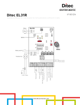
6 Electrical connections
Gearmotor FERNI and EMEGA
The ADT card should be fastened to the gearmotor terminals as shown, and connected to the control panel on terminals M, N
and R (the RA terminal is not active on the FERNI and EMEGA models).
FROG Gearmotor
Whereas with Frog, ADT card and terminals, after connecting to the cables coming out of the gearmotor, they can be left inside the control
panel or in a similar water-tight box.
BROWN
BLUE
BLUE
BROWN

,
,
A
+ -
P.
6
6 - Manual code
319U34
319U34 ver.
1.0
1.0 09/2011 © CAME cancelli automatici s.p.a. - The data and information in this manual may be changed at any time with no obligation to notify said changes.
ENGLISH
Power supply
Power supply to the
230V AC 50/60 Hz
control panel
Terminals for powering accessories:
- at 24 V (AC) powered with 230 V (AC)
- at 24 V (AC) powered with 24 V (AC)
Overall allowed power: 40 W
Electro lock connection (12V-15 W max.) with
EMEGA9
Lighting and warning devices
Movement Flasher (contact rated for: 24V AC - 25W Max.) - Flashes
while gate opens and closes.
Jumper in posiotion A - Cycle lamp Contact rated for: 24
V - 25 W Max.) :
- It lights up the driveway and stays on from the
moment the gate leaves start opening until they are
fully closed (including the automatic closing time). If
automatic closing is not activated, the lamp stays on
only during movement.
Jumper 12
page 3
"Gate open" warning light Contact rated for: 24 V - 3 W Max.)- Warns
of open gate position, turns off when gate is closed.

RX
RX
RX
RX
TX
TX
TX
TX
Dir/DeltaS
Doc/Delta
P.
7
7 - Manual code
319U34
319U34 ver.
1.0
1.0 09/2011 © CAME cancelli automatici s.p.a. - The data and information in this manual may be changed at any time with no obligation to notify said changes.
ENGLISHENGLISHENGLISH
Command devices
Stop button ((N.C.) contact.)
Gate stop button with exclusion of automatic closing, to
resume movement press command button or transmitter
button.
If unused, set DIP-switch 9 to ON.
Key switch selector and/or opening button (N.O. contact)
- Command for gate opening.
Safety devices
C1 = (N.C.) contact. di riapertura durante la chiusura»
Input for safety devices like photocells, sensitive
edges and other devices that comply with EN 12978
regulations. While the gate is closing, opening the
contact will invert movement until it is fully openend.
Shortcircuit 2 and C1 if unused
C1 = (N.C.) contact
di riapertura durante la chiusura»
C3 = N.C. "partial stop" contact
Input for safety devices like photocells, sensitive edges and
other devices that comply with EN 12978 regulations. Gate
stops if moving, triggering automatic closing .
C3 = N.C. "partial stop" contact
Key switch selector and/or command button (N.O. contact)
- Gate opening and closing commands, pressing the button or
turning the key switch selector, the gate inverts its movement
or stops depending on selection made on the DIP switches (see
selecting functions, DIP switches 1-10)
if unused

ZL170N + EMEGA + LB18 + E881
ZL170N + EMEGA + E881
P.
8
8 - Manual code
319U34
319U34 ver.
1.0
1.0 09/2011 © CAME cancelli automatici s.p.a. - The data and information in this manual may be changed at any time with no obligation to notify said changes.
ENGLISH
Detail of the ZL170N/EMEGA combination with the E881 electro-lock
6.1 Configuring the LB18 terminals
If using the LB18 battery recharger card, remove all bridges and connect the card as shown in the accompanying literature.
Factory configuration
To power the E881 lock with 24V on terminals 11-S (which are normally at 12V) do the following to the bridges:
fig. A - WITH the LB18 card, leave only one bridge on B-D and connect the card as shown in the accompanying literature.
fig. B -
WITHOUT
LB18 card, modify the the C-D bridge into B-D
fi g. A
fi g. B

/.
ON
OFF
+
SENS/RALL
-
-
+
+
TCA
-
+
-
+
SENS/VEL
-
-
+
P.
9
9 - Manual code
319U34
319U34 ver.
1.0
1.0 09/2011 © CAME cancelli automatici s.p.a. - The data and information in this manual may be changed at any time with no obligation to notify said changes.
ENGLISHENGLISHENGLISH
7 Selecting functions
10-WAY DIP-SWITCH
SPEED/SENS TRIMMER = Adjustments adjusting amperometric sensitivity while gate is moving: min/max.
DECEL/SENS = Adjustments amperometric sensitivity during deceleration: min/max.
Trimmer T.C.A. = Adjustments automatic closing time from a minimum of 1 seconds to a maximum of 120 seconds” .
1 ON - Automatic closing activated ;
2 ON - Operating the activated “open/close/invert” " button or radio command ;
2 OFF - Operating the activated “open/stop/close/stop” " button or radio command ;
3 ON - Operating the activated "open only" ” radio command ;
4 ON - Prefl ashing duringt opening and closing activated ;
5 ON - Obstacle detection activated ;
6 ON - Maintained action activated operation ” ; (excludes the radio command function)
7 ON - Ramming function activated ; (for easier lock releasing)
8 OFF - Partial stop activated with safety device connected to terminals 2-C3, (if unused, set DIP switch to ON) ;
9 OFF - "Stop" button activated ; with safety device connected to terminals 1-C2, (if unused, set DIP switch to ON)
10 - 2 - Must stay OFF
8.1 Trimmers
8 Settings
8.2 Adjusting the operating time
To memorise the operator's working time (from when it starts to open to when it is fully closed) you need to:
1. set Dip-switch 6 to ON;
2. press CH1 until gate is fully opened;
3. press CH2 and release it when the gate is completely closed;
4. Set dip-switch 6 back to OFF.

OP TIME
+
OP TIME
-
-
+
P.
10
10 - Manual code
319U34
319U34 ver.
1.0
1.0 09/2011 © CAME cancelli automatici s.p.a. - The data and information in this manual may be changed at any time with no obligation to notify said changes.
ENGLISH
8.3 Opening / closing strike zone adjustment trimmer
After setting up the deceleration spaces (see fig. C) 3) follow the "adjusting micro-switches" procedure in the gearmotor
manual, and do the following:
• set up a 60 mm X 30 mm template - keep it pressed agains one of the two strike plates as shown in fi g. 1 ( - it should be
adjusted on either the opening or closing strike plate ).
• Activate the gate - with a command button or with the transmitter - and turn the OP TIME (TL) trimmer clockwise until the
gate-leaf inverts its direction of travel the moment it touches the obstacle/template.
• Then turn the template from the short side (fi g. 2) and check that the gate leaf stops by touching the obstacle/template.
Otherwise adjust the trimmer counter-clockwise.
fi g. 3
fi g. 1
fi g. 2
A = Effective zone of the amperometric sensor with move-
ment inversion
B = Normal speed travel zone
C = Decelerated speed travel zone
D = Effective zone of the amperometric sensor with move-
ment stop
E = Closing and opening strike plates

230V
230V
0
12
24
RALL.MIN
RALL.MAX
VEL.MIN
VEL.MAX
P.
11
11 - Manual code
319U34
319U34 ver.
1.0
1.0 09/2011 © CAME cancelli automatici s.p.a. - The data and information in this manual may be changed at any time with no obligation to notify said changes.
ENGLISHENGLISHENGLISH
8.4 Opening/closing and develeration speeds
To adjust the travel and deceleration speeds, shift the fastons to the spefically shown transformer connectors.
Deceleration adjusting faston
min/max
Gate travel speed adjusting faston:
min/max
9 Amperometric Sensor
The control panel featrure an amperometric motor sensor that is triggered when an obstacle blocks its movement when opening
or closing.
It normally inverts the direction of travel, but if it is triggered when the gate is 5 cm from the closing strike plate or oepning stop,
it completely stops the gate movement (see also adjusting the OP TIME trimmer on p. 11).
The device's sensitivity is adjustable via trimmers (p. 10).
Warning! If an obstacle is detected twice consecutively while closing (and with the Automatic Closing function activated), the
operator will respond in the following way:
1) by inverting the movement, and fully opening the gate;
2) by deactivating the Automatic Closing;
3) by blocking any of the control panel functions;
To reactivate the operator you must issue a command using the transmitter or the buttons connected on 2-3 and 2-7.

CAME
C
AME
C
AM
E
C
A
M
E
C
A
M
E
CAME
CAME
CAM
E
CAM
E
CAM
E
CAME
C
AM
E
C
AM
E
CA
M
E
CAM
E
CAME
ATOMO
AT01 • AT02
AT04
TOUCH
TCH 4024 • TCH 4048
TOP
TOP-432A • TOP-434A
TOP-302A • TOP-304A
TAM
T432 • T434 • T438
TAM-432SA
TWIN
TWIN2 • TWIN4
TOP
TOP-432NA • TOP-434NA
TOP-862NA • TOP-864NA
TOP-432S
TFM
T132 • T134 • T138
T152 • T154 • T158
B
P.
12
12 - Manual code
319U34
319U34 ver.
1.0
1.0 09/2011 © CAME cancelli automatici s.p.a. - The data and information in this manual may be changed at any time with no obligation to notify said changes.
ENGLISH
10 Activating the radio command
Connect antenna cable to the apposite
terminals.
Antenna
Trasmettitori
see instruction sheet in the packaging
of the AF43SR radi-frequency card
see instructions on box
Jumper in position B -
Radio receiver's
second channel output (N.O.) contact rated:
1A-24V d.c.
Jumper 12
page 3
N.O. contact output: it closes for 3
seconds every time an opening com-
mand is given
Contact rated for: 5A-250V a..C

TOP TAM
AF
ZL170
QUADRO COMANDO
PROG
SENS VEL T LSENS RALL T C A
A BCDEF I
MORSETTIERA CARICA BATTERIE
R1
FU SIBI LE
CE NTRALI NA
630mA
FU SIBI LE
ACCESSORI
3.15A
L1 L2
230V
M NR
FU SIBI LE
CE NTRALI NA
3.15A
10 11EE35 S 1 2 3 7 C1 C3
OUT
TERMICO
B1 B2
21
34
5
67
8910
ON
21
COM RALL VEL 24V 12V
P.
13
13 - Manual code
319U34
319U34 ver.
1.0
1.0 09/2011 © CAME cancelli automatici s.p.a. - The data and information in this manual may be changed at any time with no obligation to notify said changes.
ENGLISHENGLISHENGLISH
Only for the AF43S / radio-frequency cards:
- position jumper as shown depending on the series of transmitters you are using.
AF card
Plug in the radio-frequency card onto the electronic board AFTER CUTTING OFF THE MAIN POWER SUPPLY (or disconnecting
the emergency batteries).
N.B.: The electronic card recognises the radio-frequency card only when it is powered up.
Frequency
MHz
Card
Radio-frequency
Series
transmitters
FM 26,995 AF130 TFM
FM 30.900 AF150 TFM
AM 26.995 AF26 TOP
AM 30.900 AF30 TOP
AM 433.92 AF43S / AF43SM TAM / TOP
AM 433.92 AF43TW TWIN (KeyBlock)
AM 433.92 AF43SR ATOMO
AM 40.685 AF40 TOUCH
AM 863.35 AF868 TOP
Radio frequency card

AF
ZL170
QUADRO COMANDO
PROG
SENS VEL T LSENS RALL T C A
A BCDEF I
MORSETTIERA CARICA BATTERIE
R1
FU SIBI LE
CE NTRALINA
630mA
FU SIBI LE
ACCESSORI
3.15A
L1 L2
230V
M NR
FU SIBI LE
CE NTRALINA
3.15A
10 11 E E3 5 S 1 2 3 7 C1 C3 OUT
TERMICO
B1 B2
21
34
5
67
8910
ON
21
COM RALL VEL 24V 12V
J2
AF
ZL170
QUADRO COMANDO
PROG
SENS VEL T LSENS RALL T C A
A BCDEF I
MORSETTIERA CARICA BATTERIE
R1
FU SIBI LE
CE NTRALINA
630mA
FU SIBI LE
ACCESSORI
3.15A
L1 L2
230V
M NR
FU SIBI LE
CE NTRALINA
3.15A
10 11 E E3 5 S 1 2 3 7 C1 C3 OUT
TERMICO
B1 B2
21
34
5
67
8910
ON
21
COM RALL VEL 24V 12V
J2
CH1
CH1
P.
14
14 - Manual code
319U34
319U34 ver.
1.0
1.0 09/2011 © CAME cancelli automatici s.p.a. - The data and information in this manual may be changed at any time with no obligation to notify said changes.
ENGLISH
2) The transmitter button sends the code, and the LED will stay on to signal that memorisation was succesful.
Keep button pressed “CH1"on the electronic card (the LED notification light flashes).
Memorise the code onto the card, as follows:
Flashing LED
AF radio frequency card
Memorisation
CH1
= Channel for direct commands to a gearmotor card's function (for the command type see DIP-switches 2 and 3).
CH2 = Channle for direct commands to a accessory device connected to B1-B2 (can be activated via jumper, see p. 13).
N.B.: If you later wish to change code, just repeat the above sequence.
LED stays lit
AF radio frequency card
3) Perform the same procedure withe the “CH2”button, associating it to anothe transmitter button.

P.
15
15 - Manual code
319U34
319U34 ver.
1.0
1.0 09/2011 © CAME cancelli automatici s.p.a. - The data and information in this manual may be changed at any time with no obligation to notify said changes.
ENGLISHENGLISHENGLISH
11 Dismantling and disposal
12 Statement
On its premises, CAME Cancelli Automatici S.p.A. implements a certified Environmental Management System in
compliance with the UNI EN ISO 14001 standard to ensure environmental protection.
Please help us to safeguard the environment. At CAME we believe this to be one of the fundamentals in its market operations
and development strategies. Just follow these short disposal instructions:
DISPOSING OF THE PACKAGING
The components of the packaging (i.e. cardboard, plastic, etc.) are solid urban waste and may be disposed of without much
trouble, simply by separating them for recycling.
Before proceeding it is always a good idea to check your local legislation on the matter.
DO NOT DISPOSE OF IN NATURE!
PRODUCT DISPOSAL
Our products are made up of various materials. Most of these (aluminium, plastic, iron, electric cables) are solid urban waste.
These can be disposed of at local solid waste management dumps or recycling plants.
Other components (i.e. electronic cards, remote control batteries, etc. ) may contain hazardous substances.
These must therefore be handed over the specially authorised disposal firms.
Before proceeding it is always a good idea to check your local legislation on the matter.
DO NOT DISPOSE OF IN NATURE!
MANUFACTURER'S STATEMENT
Pursuant to attachment II B of the Machines Directive 98/37/CE
CAME Cancelli Automatici S.p.A.
via Martiri della Libertà, 15
31030 Dosson di Casier - Treviso - ITALY
tel (+39) 0422 4940 - fax (+39) 0422 4941
internet: www.came.it - e-mail: [email protected]
Declares under law that the following garage door and gate automation products called:
ZL170N
...comply with the essential requirements and pertinent provisions, established by the following Directives and
also comply with the appliccable parts of the reference Regulation standards listed below.
---D
IRECTIVES
---
2006/95/CE L
OW
V
OLTAGE
D
IRECTIVE
2004/108/CE E
LECTROMAGNETIC
C
OMPATIBILITY
D
IRECTIVE
--- R
EGULATIONS
---
EN 60335-1 EN 61000-6
EN 60335-2 EN 61000-6
EN 13241-1
Reference code to request an original copy:
DDC L IT Z002g
MANAGING DIRECTOR
Mr Gianni Michielan

www.came.com www.came.it
09_2011
CAME
France
S.a.
S.a. FRANCE
7, Rue Des Haras
Z.i. Des Hautes Patures
92737
Nanterre Cedex
(+33) 0 825 825 874
(+33) 1 46 13 05 00
GERMANY
CAME Gmbh Seefeld
CAME Gmbh Seefeld
Akazienstrasse, 9
16356
Seefeld
Bei Berlin
(+49) 33 3988390
(+49) 33 39883985
CAME Automatismes S.a.
FRANCE
3, Rue Odette Jasse
13015
Marseille
(+33) 0 825 825 874
(+33) 4 91 60 69 05
U.A.E.
CAME Gulf Fze
CAME Gulf Fze
Offi ce No: S10122a2o210
P.O. Box 262853
Jebel Ali Free Zone -
Dubai
Dubai
(+971) 4 8860046
(+971) 4 8860048
CAME Automatismos S.a.
CAME Automatismos S.a. SPAIN
C/juan De Mariana, N. 17-local
28045
Madrid
(+34) 91 52 85 009
(+34) 91 46 85 442
RUSSIA
CAME Rus
CAME Rus
Umc Rus Llc
Ul. Otradnaya D. 2b, Str. 2, offi ce 219
127273,
Moscow
Moscow
(+7) 495 739 00 69
(+7) 495 739 00 69 (ext. 226)
CAME United Kingdom Ltd.
CAME United Kingdom Ltd. GREAT BRITAIN
Unit 3 Orchard Business Park
Town Street, Sandiacre
Nottingham
Nottingham - Ng10 5bp
(+44) 115 9210430
(+44) 115 9210431
PORTUGAL
CAME Portugal
CAME Portugal
Ucj Portugal Unipessoal Lda
Ucj Portugal Unipessoal Lda
Rua Liebig, nº 23
2830-141
Barreiro
Barreiro
(+351) 21 207 39 67
(+351) 21 207 39 65
CAME Group Benelux S.a.
CAME Group Benelux S.a. BELGIUM
Zoning Ouest 7
7860
Lessines
(+32) 68 333014
(+32) 68 338019
INDIA
CAME India
CAME India
Automation Solutions Pvt. Ltd
Automation Solutions Pvt. Ltd
A - 10, Green Park
110016 -
New Delhi
New Delhi
(+91) 11 64640255/256
(+91) 2678 3510
CAME Americas Automation Llc
CAME Americas Automation Llc U.S.A
11345 NW 122nd St.
Medley
Medley, FL 33178
(+1) 305 433 3307
(+1) 305 396 3331
ASIA
CAME Asia Pacific
CAME Asia Pacific
60 Alexandra Terrace #09-09
Block C, The ComTech
118 502
Singapore
Singapore
(+65) 6275 0249
(+65) 6274 8426
CAME Gmbh
GERMANY
Kornwestheimer Str. 37
70825
Korntal
Munchingen Bei Stuttgart
(+49) 71 5037830
(+49) 71 50378383
CAME Cancelli Automatici S.p.a.
CAME Cancelli Automatici S.p.a. ITALY
Via Martiri Della Libertà, 15
31030
Dosson Di Casier
Dosson Di Casier (Tv)
(+39) 0422 4940
(+39) 0422 4941
Informazioni Commerciali 800 848095
ITALY
CAME Sud s.r.l.
CAME Sud s.r.l.
Via F. Imparato, 198
Centro Mercato 2, Lotto A/7
80146
Napoli
(+39) 081 7524455
(+39) 081 7529190
CAME Service Italia S.r.l.
CAME Service Italia S.r.l. ITALY
Via Della Pace, 28
31030
Dosson Di Casier
Dosson Di Casier (Tv)
(+39) 0422 383532
(+39) 0422 490044
Assistenza Tecnica 800 295830
Assistenza Tecnica 800 295830
ITALY
CAME Global Utilities s.r.l.
CAME Global Utilities s.r.l.
Via E. Fermi, 31
20060
Gessate
Gessate (Mi)
(+39) 02 95380366
(+39) 02 95380224
English
English - Manual code
319U34
319U34 ver.
1.0
1.0 09/2011 © CAME cancelli automatici s.p.a.
The data and information in this manual may be changed at any time and without obligation on the part of Came Cancelli Automatici S.p.a. to notify said changes.
/