
L8542945
10/2011 rev 1
UNIONE NAZIONALE COSTRUTTORI
AUTOMATISMI PER CANCELLI, PORTE
SERRANDE ED AFFINI
SC.RF

2
67 mm
90 mm
26 mm
Fig.1

3
BZ
LD1
N.C. N.C.
W1/W2
CLOSE
BZ-12/24
CLOSE
DEFAULT
12/24
W2
W1
CH1 CH2 12/24V TSTANT
P
(+)(-)
ANT
SHIELD
Fig.2

6
SC.RF
DESCRIPTION
Two-channel radio receiver, with 868 MHz frequency, pursuant
to the regulation EN 12978, to be matched to radio transmitters
of the RF/RF SUN series for movable clsoures.
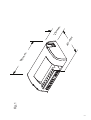
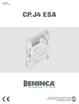
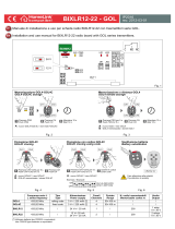
OVERALL DIMENSIONS
The overall dimensions of the radio-receiver box are shown in
Figure 1. A bi-adhesive strip is supplied to apply the box inside
the automation system or the control system.
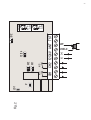
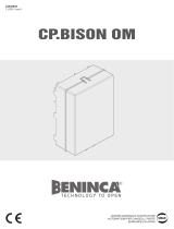
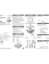
WIRE CONNECTIONS (Fig. 4)
CH1* Output, channel 1 replies the status of the sensitive sa-
fety edge memorised on channel 1 – normally closed
contact.
CH2* Output, channel 2 replies the status of the sensitive sa-
fety edge memorised on channel 2 – normally closed
contact.
12/24 Input, 12 or 24 VAC or VDC power supply. It can be
selected through a 12/24 jumper. In case of 12/24 VDC
power supply, keep to poles shown in Figure 2.
ANT Input, antenna. For a better reception, it might be ne-
cessary to remove the pre-installed cable and use a
868MHz antenna.
TST Not use
* CH1 and CH2 outputs are mainly connected to inputs for the
sensitive edge of the control unit. In this case, inputs
should be preset as if they were connected to a safety
edge of the mechanical type.
The inputs for sensitive safety edges usually provide that, in the
event they are activated, the system is immediately stopped and
the movement is reversed for some seconds.
As an alternative, should no inputs be provided for sensitive
safety edges, channels CH1/CH2 can be connected to other
safety inputs, namely inputs for photocells or inputs for STOP
control signals.
If two channels must be connected to one single input in the
control system, the two outputs should be connected in series.
JUMPER
SC.RF is equipped with 2 jumpers for the following pre-set-
tings:
BZ: The acoustic signal is enabled or disabled.
Closed jumper: activated sound indicator
Open jumper: not activated buzzer
12/24:
Power voltage is selected.
Closed jumper: 12 VAC/DC
Open jumper: 24 VAC/VDC
HOW TO STORE THE RADIO TRANSMITTER IN MEMORY
In order to be able to communicate with the RF/RF.SUN radio-
transmitter, the transmitter code must be memorised and assi-
gned to either channels available.
In order to memorise the code on channel 1, proceed as fol-
lows:
1) Press push-button P of the SC-RF RECEIVER once
2) The LED LD1 switches on with RED light
3) Within 30 seconds, press push-button S1 of the RF/RF.SUN
device for around 4 seconds.
4) The LED LD1 switches off temporarily and a buzz indicates
that the storage in memory has been successful.
5) Await that the LED LD1 switches off

7
In order to memorise the code on channel 2, proceed as follows:
1) Press push-button P of the SC-RF RECEIVER once
2) The LED LD1 switches on with RED light.
3) Press push-button P once again
4) The LED LD1 switches to GREEN light.
5) Within 30 seconds, press push-button S1 of the RF/RF.SUN
device for around 4 seconds.
6) The LED LD1 switches off temporarily and a buzz indicates
that the storage in memory has been successful.
7) Await that the LED LD1 switches off.
IMPORTANT!
Up to 4 different devices can be memorised on each sin-
gle channel. When the memory available is full, the LED will
flash three times.
HOW TO RESET THE SC.RF RECEIVER
If all presetting must be erased and the SC.RF receiver must be
restored to factory pre-setting:
- Cut power supply off.
- Press push-button P and keep it pressed.
- Power the system again, keeping the push-button P pressed
on the receiver.
- The LED starts flashing with red/green light. After around 5
seconds, when the light turns orange, release the button P and
wait that the LED switches off.
DIAGNOSTICS
During normal operation, the colour of the LED indicates the
status of the two channels:
Red LED – channel 1 activated
Green LED – channel 2 activated
The Buzzer (if enabled) indicates the following events:
- device switching on
- exit from configuration menu
- down battery of the mobile device (also the LED on the mobile
device switches on periodically).
DISPOSAL
When the product is out of order, it must be disposed accor-
ding to regulations in force on waste disposal and recycling of
the various components (metal, plastics, electrical wires, etc.).
For this purpose, it is advisable to contact your installer or a
specialised company.
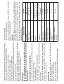
Specification SC.RF
Frequency 868 MHz
Power supply 12/24 Vac/Vdc
Protection level IP 30
Range
Without antenna - 30m
With antenna - 100m
Channels
2 (4 devices max for each
channel)
Relay contact 1A/24 Vdc
Operating time -20/+50°C
Consumption at rest 10 mA
Consumption with 1
channel
42 mA
Consump. 2 channels
activated
66 mA

AUTOMATISMI BENINCÀ SpA
Via Capitello, 45 - 36066 Sandrigo (VI) - Tel. 0444 751030 r.a. - Fax 0444 759728
-
 1
1
-
 2
2
-
 3
3
-
 4
4
-
 5
5
-
 6
6


Ask a question and I''ll find the answer in the document
Finding information in a document is now easier with AI
Related papers


Other documents
-
Telcoma T124 Owner's manual
-
-
 DITEC GOL4, GOL4C Owner's manual
-
-
Genius Zenith Operating instructions
-
-
 Contrive RadioControl-4 User manual
-
-
-

