
EPSON RC+ 7.0 Option
Vision Guide 7.0
Hardware & Setup
Rev.3 EM179S3541F
Ver.7.3

EPSON RC+ 7.0 Option Vision Guide 7.0 (Ver.7.3) Hardware & Setup Rev.3

Vision Guide 7.0 (Ver.7.3) Hardware & Setup Rev.3 i
EPSON RC+ 7.0 Option
Vision Guide 7.0 (Ver.7.3) Hardware & Setup
Rev.3
Copyright 2012-2017 SEIKO EPSON CORPORATION. All rights reserved.

ii Vision Guide 7.0 (Ver.7.3) Hardware & Setup Rev.3
FOREWORD
Thank you for purchasing our robot products. This manual contains the information
necessary for the correct use of the EPSON RC+ software.
Please carefully read this manual and other related manuals when using this software.
Keep this manual in a handy location for easy access at all times.
WARRANTY
The robot and its optional parts are shipped to our customers only after being subjected
to the strictest quality controls, tests and inspections to certify its compliance with our
high performance standards.
Product malfunctions resulting from normal handling or operation will be repaired free
of charge during the normal warranty period. (Please ask your Regional Sales Office
for warranty period information.)
However, customers will be charged for repairs in the following cases (even if they
occur during the warranty period):
1. Damage or malfunction caused by improper use which is not described in the
manual, or careless use.
2. Malfunctions caused by customers’ unauthorized disassembly.
3. Damage due to improper adjustments or unauthorized repair attempts.
4. Damage caused by natural disasters such as earthquake, flood, etc.
Warnings, Cautions, Usage:
1. If the robot or associated equipment is used outside of the usage conditions
and product specifications described in the manuals, this warranty is void.
2. If you do not follow the WARNINGS and CAUTIONS in this manual, we
cannot be responsible for any malfunction or accident, even if the result is
injury or death.
3. We cannot foresee all possible dangers and consequences. Therefore, this
manual cannot warn the user of all possible hazards.
SOFTWARE LICENSE
For Compact Vision users, please read this software license agreement carefully before
using this option.
Appendix A: End User License Agreement for Compact Vision
Appendix B: Open Source Software License for Compact Vision
TRADEMARKS
Microsoft, Windows, Windows logo, Visual Basic, and Visual C++ are either
registered trademarks or trademarks of Microsoft Corporation in the United States
and/or other countries.
Other brand and product names are trademarks or registered trademarks of the
respective holders.

Vision Guide 7.0 (Ver.7.3) Hardware & Setup Rev.3 iii
TRADEMARK NOTIFICATION IN THIS MANUAL
Microsoft® Windows® XP Operating system
Microsoft® Windows® Vista Operating system
Microsoft® Windows® 7 Operating system
Microsoft® Windows® 8 Operating system
Microsoft® Windows® 10 Operating system
Throughout this manual, Windows XP, Windows Vista, Windows 7, Windows 8, and
Windows 10 refer to above respective operating systems. In some cases, Windows refers
generically to Windows XP, Windows Vista, Windows 7, Windows 8, and Windows 10.
NOTICE
No part of this manual may be copied or reproduced without authorization.
The contents of this manual are subject to change without notice.
Please notify us if you should find any errors in this manual or if you have any
comments regarding its contents.
MANUFACTURER

iv Vision Guide 7.0 (Ver.7.3) Hardware & Setup Rev.3
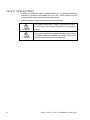
SAFETY PRECAUTIONS
Installation of robots and robotic equipment should only be performed by qualified
personnel in accordance with national and local codes. Please carefully read this
manual and other related manuals when using this software.
Keep this manual in a handy location for easy access at all times.
WARNING
This symbol indicates that a danger of possible serious injury
or death exists if the associated instructions are not followed
properly.
CAUTION
This symbol indicates that a danger of possible harm to people
or physical damage to equipment and facilities exists if the
associated instructions are not followed properly.

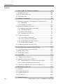
Table of Contents
Vision Guide 7.0 (Ver.7.3) Hardware & Setup Rev.3 v
Installation
1. Manuals and On-line Help 3
1.1 Vision Guide Manual Construction .......................................................3
Vision Guide 7.0 Hardware & Setup (this manual) ...............................3
Vision Guide 7.0 Software (separate volume) ......................................4
Vision Guide 7.0 Properties & Results Reference (separate volume) .4
1.2 Related Manuals ...................................................................................5
1.3 Using On-Line Help ..............................................................................5
2. Safety 6
2.1 Conventions ..........................................................................................6
2.2 Safety Precautions ...............................................................................6
2.3 Robot Safety .........................................................................................6
3. Checking of Included Items 7
3.1 Included Items for Compact Vision CV1 ..............................................7
3.2 Included Items for Compact Vision CV2 ..............................................8
3.3 Included Items for PC Vision PV1 ........................................................9
4. System Configuration 10
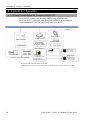
4.1 System Configuration for Compact Vision CV1 .................................10
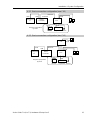
4.1.1 Basic connection configuration (one CV1) ...............................11
4.1.2 Basic connection configuration (two CV1) ................................11
4.1.3 Two Robot Controllers and one CV1 ........................................11
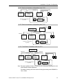
4.2 System Configuration for Compact Vision CV2 .................................12
4.2.1 Basic connection configuration (one CV2) ...............................13
4.2.2 Basic connection configuration (two CV2) ................................13
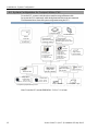
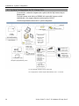
4.3 System Configuration for PC Vision PV1 ...........................................14
4.3.1 System Requirements ...............................................................15
4.3.2 Basic connection configuration (1 GigE camera) .....................18
4.3.3 Basic connection configuration
(using PoE switch, 2 GigE camera) ..........................................18
Hardware
1. Compact Vision CV1 21
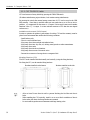
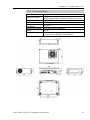
1.1 Installation Precautions ......................................................................21
1.1.1 Part Names and Functions .......................................................21
1.1.2 CV1 LED Display ......................................................................22
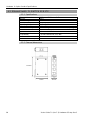
1.1.3 CV1 Specifications ....................................................................23

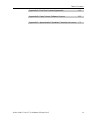
Table of Contents
vi Vision Guide 7.0 (Ver.7.3) Hardware & Setup Rev.3
1.2 Wiring of CV1 ..................................................................................... 24
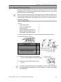
1.2.1 Power Supply ............................................................................ 24
1.2.2 Grounding ................................................................................. 24
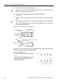
1.2.3 24VDC wiring ............................................................................ 25
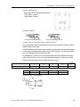
1.2.4 Ethernet Cable .......................................................................... 26
1.3 Maintenance ....................................................................................... 28
1.3.1 Fan Filter ................................................................................... 28
1.3.2 Updating CV1 Firmware ........................................................... 28
2. Compact Vision CV2 30
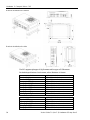
2.1 Installation Precautions ...................................................................... 30
2.1.1 Part Names and Functions ....................................................... 30
2.1.2 CV2 LED Display ...................................................................... 31
2.1.3 CV2 TRIGGER Switch .............................................................. 32
2.1.4 CV2 Specifications .................................................................... 33
2.2 Wiring of CV2 ..................................................................................... 35
2.2.1 Power Supply ............................................................................ 35
2.2.2 24VDC wiring ............................................................................ 35
2.2.3 Ethernet Cable .......................................................................... 36
2.3 Maintenance ....................................................................................... 38
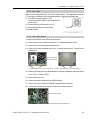
2.3.1 Internal Structure of CV2 .......................................................... 38
2.3.2 Fan Filter ................................................................................... 39
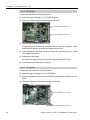
2.3.3 LED / SW Board ........................................................................ 39
2.3.4 PoE Board ................................................................................. 40
2.3.5 CPU board ................................................................................ 40
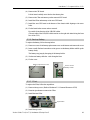
2.3.6 Backup Battery .......................................................................... 41
2.3.7 CFast ......................................................................................... 41
2.3.8 Memory ..................................................................................... 42
2.3.9 Chassis Fan .............................................................................. 42
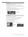
2.3.10 Updating CV2 Firmware ......................................................... 43
2.3.11 Resetting to the Factory Default ............................................. 44
3. PC Vision PV1 45
3.1 Installation Precautions ...................................................................... 45
3.2 Wiring of PV1 ..................................................................................... 45
3.2.1 Ethernet Cable .......................................................................... 45
4. Camera 47
4.1 USB Camera ...................................................................................... 47
4.1.1 Camera Cable Wiring ............................................................... 47

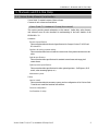
Table of Contents
Vision Guide 7.0 (Ver.7.3) Hardware & Setup Rev.3 vii
4.1.2 Part Names and Functions .......................................................48
4.1.3 External Wiring ..........................................................................48
4.1.4 USB Camera Specifications ......................................................50
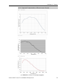
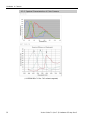
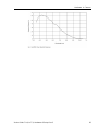
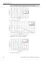
4.1.5 Spectral Characteristics of Monochrome Camera ....................51
4.1.6 Spectral Characteristics of Color Camera ................................52
4.2 GigE camera .......................................................................................53
4.2.1 GigE Camera Cable, Trigger Cable ..........................................53
4.2.2 Part Names and Functions .......................................................54
4.2.3 External Wiring ..........................................................................54
4.2.4 GigE Camera Specification .......................................................59
4.2.5 Power Specification...................................................................61
4.2.6 CCD/CMOS Spectral Characteristics of Monochrome
Camera .....................................................................................62
4.2.7 CCD/CMOS Spectral Characteristics of Color Camera ...........64
5. Camera Lens 65
5.1 Standard Camera Lens ......................................................................65
5.1.1 Lens specification ......................................................................65
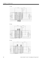
5.1.2 Outline Drawing .........................................................................65
5.2 Megapixel Camera Lens ....................................................................67
5.2.1 Lens Specification .....................................................................67
5.2.2 Outline Drawing .........................................................................67
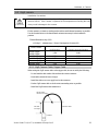
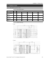
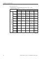
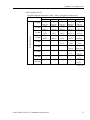
5.3 Extension Tube ...................................................................................69
5.3.1 Extension Tube Work Distance ................................................69
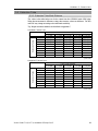
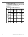
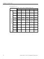
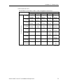
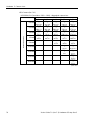
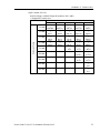
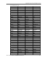
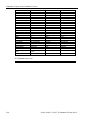
5.3.2 Extension Tube FOV Table .......................................................70
6. Option Product Specifications 78
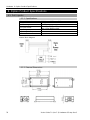
6.1 PoE Injector ........................................................................................78
6.1.1 Specifications ............................................................................78
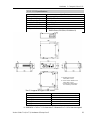
6.1.2 External Dimensions .................................................................78
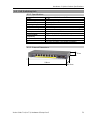
6.2 PoE Switching Hub .............................................................................79
6.2.1 Specifications ............................................................................79
6.2.2 External Dimensions .................................................................79
6.3 Ethernet Switch FL SWITCH SFN 5TX .............................................80
6.3.1 Specifications ............................................................................80
6.3.2 External dimensions ..................................................................80
6.4 Camera Mounting Brackets ................................................................81
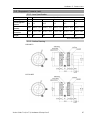
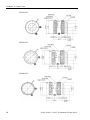
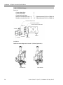
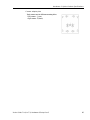
6.4.1 6-Axis Robot ..............................................................................81
6.4.2 SCARA Robot ...........................................................................84

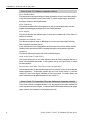
Table of Contents
viii Vision Guide 7.0 (Ver.7.3) Hardware & Setup Rev.3
Set Up
1. Vision Guide 7.0 Software Installation 89
1.1 Software Option Key .......................................................................... 89
1.2 PV1 Software Option Key .................................................................. 89
1.3 OCR Option Key ................................................................................. 89
2. Software Configuration 90
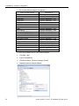
2.1 Network Configuration of Development PC and Vision PC ............... 91
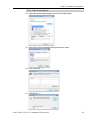
2.1.1 LAN setting ............................................................................... 91
2.1.2 Disabling the Firewall ................................................................. 92
2.2 Network Configuration of Vision PC ................................................... 93
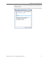
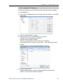
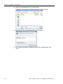
2.2.1 Network Driver Setting Confirmation ......................................... 93
2.2.2 Filter Driver Setting ................................................................... 95
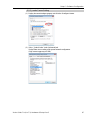
2.2.3 Jumbo Frame Setting ................................................................ 97
2.2.4 Precautions for Vision PC ......................................................... 98
2.3 Camera Configuration ...................................................................... 101
2.3.1 PV1 Camera Configuration ..................................................... 101
2.3.2 CV1/CV2 Camera Configuration ............................................ 103
2.3.3 Using Multiple CV1/CV2 Cameras ......................................... 105
2.3.4 Virtual Camera Function ......................................................... 106
2.4 Configure Controller LAN Port TCP/IP............................................. 107
3. How to Use the Compact Vision Monitor 108
3.1 Connecting Monitor, Mouse, Keyboard ........................................... 108
3.2 Monitor Main Screen ........................................................................ 108
3.3 Configuration Dialog ......................................................................... 111
4. Connection 116
4.1 Testing the Vision System ................................................................ 116
4.2 Operation Check of Vision Guide 7.0............................................... 116
4.2.1 Start EPSON RC+ 7.0 and create a new project ................... 116
4.2.2 Checking of Input Image from Camera .................................. 117
4.3 Checking and Adjusting for Proper Focal Distance ......................... 118
5. Maintenance Parts List 119
5.1 Common ........................................................................................... 119
5.2 Compact Vision CV1 ........................................................................ 120
5.3 Compact Vision CV2 ........................................................................ 120
5.4 PC Vision PV1 .................................................................................. 120
6. Trouble Shooting 121

Table of Contents
Vision Guide 7.0 (Ver.7.3) Hardware & Setup Rev.3 ix
Appendix A: End User License Agreement A-1
Appendix B: Open Source Software License B-1
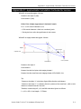
Appendix C: Approximate Calculation Formulas for Lenses C-1

Table of Contents
x Vision Guide 7.0 (Ver.7.3) Hardware & Setup Rev.3

Installation
The following chapters contain informat
ion to be known
before using
Vision Guide.
Please be sure to read the
se chapters.


Installation 1. Manuals and On-line Help
Vision Guide 7.0 (Ver.7.3) Hardware & Setup Rev.3 3
1. Manuals and On-line Help
1.1 Vision Guide Manual Construction
Vision Guide 7.0 manual consists of three volumes.
Contents of each volume are listed below.
Vision Guide 7.0 Hardware & Setup (this manual)
This section provides general information on this manual. Online help, safety features,
and reference cases are also described for understanding of the basic features of the
EPSON RC+ 7.0
Hardware
Electrical specification:
This section describes the electrical specification for Compact Vision CV1/CV2 and
PC vision PV1.
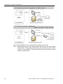
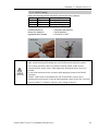
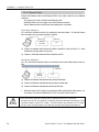
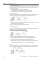
Cautions for wiring camera cables:
This section describes how to install the camera to the fixed position and mount to the
robot.
Optical specification:
This section describes specifications for standard camera lenses and mega-pixel
camera lenses.
Option product specification:
This section describes specifications for other optional products. (PoE Injector, PoE
switch, robot mounting options, etc.)
Maintenance parts
Setup
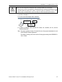
How to Install:
This section describes the necessary system, product configuration of the Vision Guide
7.0 and how to install the hardware and software.
Camera configuration
Confirmation of setup

Installation 1. Manuals and On-line Help
4 Vision Guide 7.0 (Ver.7.3) Hardware & Setup Rev.3
Vision Guide 7.0 Software (separate volume)
Vision Guide Window
This section shows the layout and gives a usage explanation for the Vision Guide window.
It also includes information on the Vision Guide 7.0 toolbar, Image Display, Run Panel,
the Object, Sequence, and Calibration tabs.
Vision Sequences
This section describes what vision sequences are, how to use and apply them, and also
explains about debugging techniques for Vision Guide Sequences.
Vision Objects
This section describes the different types of vision tools available with Vision Guide 7.0
and how to use them.
Histogram and Statistics Tools
This section describes the usage of Histogram for various vision object types including
Blob, Correlation, and Polar objects.
It also describes the Vision Guide statistics tools from the Vision Guide window with the
Statistics dialog and from the SPEL+ Language through accessing statistics properties.
Calibration
This section explains the usage for the various calibration types.
Using Vision Guide 7.0 with SPEL+
This section shows how to run vision sequences from the SPEL+ language and how to
access vision properties and results. It also explains how to use Vision Guide 7.0 results
for robot guidance.
Case Studies: Quick start: First Vision Guide 7.0 Application
This section describes for the users first using the Vision Guide 7.0 how to use it using the
sample applications. It thoroughly explains the use of the Vision Guide 7.0, from the
creation of a new vision object, calibration of the Vision Guide 7.0 mobile camera, and
actual robot motion to the parts detected by Vision Guide 7.0.
Vision Guide 7.0 Properties & Results Reference (separate volume)
This volume contains a complete reference of all the properties and results available for
vision sequences and vision objects. It contains detailed information relating to the proper
usage, cautions, and warnings for each property and result.

Installation 1. Manuals and On-line Help
Vision Guide 7.0 (Ver.7.3) Hardware & Setup Rev.3 5
1.2 Related Manuals
Refer to the following related manuals along with the Vision Guide 7.0 manuals for using
the Vision Guide 7.0.
EPSON RC+7.0 User's Guide
This manual contains information on using the EPSON RC+ Robot Control System.
SPEL
+
Language Reference Manual
This manual contains a complete description of all commands for the SPEL
+
language.
Each Robot Manual
Each robot manual contains information on our robots.
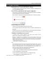
1.3 Using On-Line Help
EPSON RC+ 7.0 supports the On-Line Help system. The help system makes it easy to
find information than the conventional method using manuals.
There are several ways to refer to the on-line help in EPSON RC+ 7.0:
- Press the F1 function key at any time for context sensitive help. Help will be displayed
for the current item you are working with. This is very useful when you need
information for a certain item in a screen or dialog. If you are editing a program, the
help information for the SPEL
+
keyword at the cursor position will be displayed. You
can use the on-line help for referring syntax information to use the SPEL
+
language.
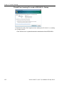
- Click on the <Help> button in the dialog box, if available.
- To view the table of contents and select topics, select Contents from the Help menu.
Topics can be selected by clicking on the underlined text that is highlighted in green.
(This causes a jump to the topic of interest.)
- Select Contents from the Help menu, then press <S> or click the <Search> button to
search for information on a specific topic.
Once you are in the on-line help you will notice that some items are highlighted in green
and underlined. These are hypertext links and when you click on this highlighted text, the
system will jump to the area in the Help System that is related to the highlighted text. You
will also notice that some text is highlighted in green with dotted underlines. Clicking on
this type of text will cause a small popup window to appear with a more detailed
description of the highlighted text and possibly related information that you can jump to.
Most of the information found in this manual is also available in the Vision Guide 7.0
Help System although it may be arranged a little differently to provide the proper
hypertext links and ease of use.

Installation 2. Safety
6 Vision Guide 7.0 (Ver.7.3) Hardware & Setup Rev.3
2. Safety
Please read this manual before using the Vision Guide.
Keep this manual handy for easy access at all times and reread it when you find anything
unclear.
2.1 Conventions
Important safety considerations are indicated throughout the manual by the following
symbols. Be sure to read the descriptions shown with each symbol.
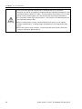
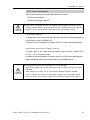
WARNING
This symbol indicates that a danger of possible serious injury or death
exists if the associated instructions are not followed properly.
WARNING
This symbol indicates that a danger of possible harm to people caused
by electric shock exists if the associated instructions are not followed
properly.
CAUTION
This symbol indicates that a danger of possible harm to people or
physical damage to equipment and facilities exists if the associated
instructions are not followed properly.
2.2 Safety Precautions
WARNING
■
Do not use the product for the purpose to ensure safety.
■
The product must be
used within the conditions described in this
manual.
Using the product in an environment that exceeds the specified
environmental conditions may not only shorten the life cycle of the
product but may also cause serious safety problems.
CAUTION
■
Purchase cameras and camera cables from our suppliers.
Note that cameras and camera cables of other manufacturers are not
included in the warranty.
2.3 Robot Safety
Whenever you are working with robots or other automation equipment, safety must be the
top priority. The EPSON RC+ 7.0 system has many safety features built in, such as E-
Stop and a Safety Guard Input. These safety features should be used when designing the
robot cell.
Refer to the Safety chapter in this manual for safety information and guidelines.

Installation 3. Checking of Included Items
Vision Guide 7.0 (Ver.7.3) Hardware & Setup Rev.3 7
3. Checking of Included Items
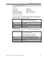
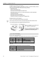
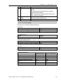
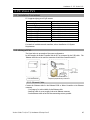
3.1 Included Items for Compact Vision CV1
Compact Vision CV1 body
Power source connector
Main optional products
NS1044BU (Standard monochrome camera)
NS4133BU (1.3 mega-pixel monochrome camera)
NS4133CU (1.3 mega-pixel color camera)
NS1500BU (5 mega-pixel monochrome camera) *1
NS1500CU (5 mega-pixel color camera) *1
Flexible USB camera cable (5 m) Standard USB camera cable (5 m)
Flexible USB camera trigger cable (5 m) Standard USB camera trigger cable (5 m)
Standard camera lens (8 mm, 12 mm, 16 mm, 25 mm, 50 mm)
Megapixel camera lens (8 mm, 12 mm, 16 mm, 25 mm, 50 mm)
OCR 7.0 license
*1: EPSON RC+ 7.0 Ver. 7.0.2 or later and CV1 firmware Ver. 2.1.0.6 or later are
required.
Note:
OCR 7.0 license is setup to the robot controller.
When you change the robot controller connected to the CV1, the OCR 7.0 license should
be setup in the new controller as well. If the OCR 7.0 license is not setup in the connected
controller, the OCR function is invalid.

Installation 3. Checking of Included Items
8 Vision Guide 7.0 (Ver.7.3) Hardware & Setup Rev.3
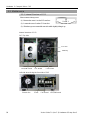
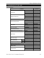
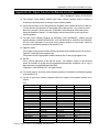
3.2 Included Items for Compact Vision CV2
Compact Vision CV2 body
Power source connector
Rubber foot (4 pcs)
Mounting bracket (1 set)
Connector covers (2 pcs)
Main optional products
acA640-100gm (Standard monochrome camera)
acA640-120gm (Standard 2 monochrome camera)
acA1600-20gm (2 mega-pixel monochrome camera)
acA1600-20gc (2 mega-pixel color camera)
acA1600-60gm (2 mega-pixel 2 monochrome camera)
acA1600-60gc (2 mega-pixel 2 color camera)
}
acA2500-14gm (5 mega-pixel monochrome camera)
acA2500-14gc (5 mega-pixel color camera)
acA3800-10gm (10 mega-pixel monochrome camera)
NS1044BU (Standard monochrome camera)
NS4133BU (1.3 mega-pixel monochrome camera)
NS4133CU (1.3 mega-pixel color camera)
NS1500BU (5 mega-pixel monochrome camera)
NS1500CU (5 mega-pixel color camera)
Flexible GigE camera cable (5m, 10m) CAT5e Ethernet cable (5m, 10m)
Flexible GigE camera trigger cable (5m, 10m)
Flexible USB camera cable (5m) Standard USB camera cable (5m)
Flexible USB camera trigger cable (5m) Standard USB camera trigger cable (5m)
Standard lens (8 mm, 12 mm, 16 mm, 25 mm, 50 mm)
Megapixel lens (8 mm, 12 mm, 16 mm, 25 mm, 50 mm)
OCR7.0 license
Note:
OCR 7.0 license is setup to the robot controller.
When you change the robot controller to be connected, the OCR 7.0 license should be
setup in the new controller as well. If the OCR 7.0 license is not setup in the connected
controller, the OCR function is invalid.
Page is loading ...
Page is loading ...
Page is loading ...
Page is loading ...
Page is loading ...
Page is loading ...
Page is loading ...
Page is loading ...
Page is loading ...
Page is loading ...
Page is loading ...
Page is loading ...
Page is loading ...
Page is loading ...
Page is loading ...
Page is loading ...
Page is loading ...
Page is loading ...
Page is loading ...
Page is loading ...
Page is loading ...
Page is loading ...
Page is loading ...
Page is loading ...
Page is loading ...
Page is loading ...
Page is loading ...
Page is loading ...
Page is loading ...
Page is loading ...
Page is loading ...
Page is loading ...
Page is loading ...
Page is loading ...
Page is loading ...
Page is loading ...
Page is loading ...
Page is loading ...
Page is loading ...
Page is loading ...
Page is loading ...
Page is loading ...
Page is loading ...
Page is loading ...
Page is loading ...
Page is loading ...
Page is loading ...
Page is loading ...
Page is loading ...
Page is loading ...
Page is loading ...
Page is loading ...
Page is loading ...
Page is loading ...
Page is loading ...
Page is loading ...
Page is loading ...
Page is loading ...
Page is loading ...
Page is loading ...
Page is loading ...
Page is loading ...
Page is loading ...
Page is loading ...
Page is loading ...
Page is loading ...
Page is loading ...
Page is loading ...
Page is loading ...
Page is loading ...
Page is loading ...
Page is loading ...
Page is loading ...
Page is loading ...
Page is loading ...
Page is loading ...
Page is loading ...
Page is loading ...
Page is loading ...
Page is loading ...
Page is loading ...
Page is loading ...
Page is loading ...
Page is loading ...
Page is loading ...
Page is loading ...
Page is loading ...
Page is loading ...
Page is loading ...
Page is loading ...
Page is loading ...
Page is loading ...
Page is loading ...
Page is loading ...
Page is loading ...
Page is loading ...
Page is loading ...
Page is loading ...
Page is loading ...
Page is loading ...
Page is loading ...
Page is loading ...
Page is loading ...
Page is loading ...
Page is loading ...
Page is loading ...
Page is loading ...
Page is loading ...
Page is loading ...
Page is loading ...
Page is loading ...
Page is loading ...
Page is loading ...
Page is loading ...
Page is loading ...
Page is loading ...
Page is loading ...
Page is loading ...
Page is loading ...
Page is loading ...
Page is loading ...
Page is loading ...
Page is loading ...
Page is loading ...
-
 1
1
-
 2
2
-
 3
3
-
 4
4
-
 5
5
-
 6
6
-
 7
7
-
 8
8
-
 9
9
-
 10
10
-
 11
11
-
 12
12
-
 13
13
-
 14
14
-
 15
15
-
 16
16
-
 17
17
-
 18
18
-
 19
19
-
 20
20
-
 21
21
-
 22
22
-
 23
23
-
 24
24
-
 25
25
-
 26
26
-
 27
27
-
 28
28
-
 29
29
-
 30
30
-
 31
31
-
 32
32
-
 33
33
-
 34
34
-
 35
35
-
 36
36
-
 37
37
-
 38
38
-
 39
39
-
 40
40
-
 41
41
-
 42
42
-
 43
43
-
 44
44
-
 45
45
-
 46
46
-
 47
47
-
 48
48
-
 49
49
-
 50
50
-
 51
51
-
 52
52
-
 53
53
-
 54
54
-
 55
55
-
 56
56
-
 57
57
-
 58
58
-
 59
59
-
 60
60
-
 61
61
-
 62
62
-
 63
63
-
 64
64
-
 65
65
-
 66
66
-
 67
67
-
 68
68
-
 69
69
-
 70
70
-
 71
71
-
 72
72
-
 73
73
-
 74
74
-
 75
75
-
 76
76
-
 77
77
-
 78
78
-
 79
79
-
 80
80
-
 81
81
-
 82
82
-
 83
83
-
 84
84
-
 85
85
-
 86
86
-
 87
87
-
 88
88
-
 89
89
-
 90
90
-
 91
91
-
 92
92
-
 93
93
-
 94
94
-
 95
95
-
 96
96
-
 97
97
-
 98
98
-
 99
99
-
 100
100
-
 101
101
-
 102
102
-
 103
103
-
 104
104
-
 105
105
-
 106
106
-
 107
107
-
 108
108
-
 109
109
-
 110
110
-
 111
111
-
 112
112
-
 113
113
-
 114
114
-
 115
115
-
 116
116
-
 117
117
-
 118
118
-
 119
119
-
 120
120
-
 121
121
-
 122
122
-
 123
123
-
 124
124
-
 125
125
-
 126
126
-
 127
127
-
 128
128
-
 129
129
-
 130
130
-
 131
131
-
 132
132
-
 133
133
-
 134
134
-
 135
135
-
 136
136
-
 137
137
-
 138
138
-
 139
139
-
 140
140
-
 141
141
-
 142
142
-
 143
143
-
 144
144


Epson CV1 Vision Guidance User manual
- Type
- User manual
- This manual is also suitable for
Ask a question and I''ll find the answer in the document
Finding information in a document is now easier with AI
Related papers
-
Epson Vision Guide Owner's manual
-
Epson T6 SCARA Robots Installation guide
-
-
-
Epson C8 Compact 6-Axis Robots User guide
-
-
-
-
-
Epson IntelliFlex Feeding System User manual
Other documents
-
 Liehuzhekeji Car Backup Camera and Monitor Kit, 7 Inch HD Quad Split Monitor 4 Pieces Waterproof IR Night Vision Front&Rear&Side View Cameras for Car RV Truck Pickup Van Camper Reversing Use User manual
-
Perle PINJ30 Installation guide
-
Aiphone TW-LCB Wiring Instructions
-
Manhattan 460415 Datasheet
-
 Barnett Engineering 1272M001 User manual
-
EDWARDS 117 Series Installation guide
-
-
Fujifilm 16276479 User manual
-
Basler Cameras Used Installation guide
-

