Page is loading ...

UT700
ENCRYPTED DIGITAL
UHF HANDHELD TRANSMITTER
LECTROSONICS, INC.
Rio Rancho, NM
www.lectrosonics.com
OPERATING INSTRUCTIONS
and trouble-shooting guide

2
UT700
LECTROSONICS, INC.
INTRODUCTION
The 700 Series wireless system provides a combination of outstanding audio quality
and secure encryption. This unique combination makes the 700 Series equally
suitable for high-end studio and stage applications, and for corporate and govern-
ment applications where security is a concern.
Several advantages are provided by a digital wireless system:
• A digital radio system provides outstanding signal to noise ratio.
• The signal to noise ratio of a digital radio system stays constant all the way out to
the end of the usable range of RF signal strength.
• A DSP controlled analog limiter provides superior level control.
• Eavesdropping is extremely difficult due to the secure encryption.
The UT700 is an integral microphone/transmitter with an internal antenna. The
antenna is a dipole type utilizing the two printed circuit boards as the elements. The
housing is composed of durable PVC, machined to a natural, comfortable shape.
Internal mechanical parts are machined aluminum and brass.
Only the UT700 transmitters are covered in this manual. Companion receivers are
covered in separate manuals.
TABLE OF CONTENTS
The UT700 transmitter is FCC type accepted under Part 74: 470-608MHz and 614-802MHz
INTRODUCTION ................................................................................................... 2
GENERAL TECHNICAL DESCRIPTION ............................................................. 3
CONTROLS AND FUNCTIONS ........................................................................... 6
VARIMIC CONTROLS ........................................................................................... 8
BATTERY INSTALLATION .................................................................................. 10
OPERATING INSTRUCTIONS ........................................................................... 11
OPERATING NOTES........................................................................................... 11
ADJUSTING THE TRANSMITTER FREQUENCY ............................................ 11
TROUBLESHOOTING......................................................................................... 12
SPECIFICATIONS AND FEATURES ................................................................. 14
SERVICE AND REPAIR ...................................................................................... 15
RETURNING UNITS FOR REPAIR.................................................................... 15
WARRANTY ........................................................................................... Back cover

3
Digital Frequency Agile UHF Hand-held Transmitter
Rio Rancho, NM – USA
GENERAL TECHNICAL DESCRIPTION
GENERAL
The 700 series encrypted digital wireless microphones use an all-digital communications link for excellent sound
quality and data security.
In the transmitter, the audio first passes through a DSP-controlled dual envelope analog limiter. The signal is then
digitized and fed to a DSP (digital signal processor). The DSP uses a proprietary audio encoding scheme to lower
the bit rate and provide the high entropy required for secure encryption. The bit stream is then encrypted, appor-
tioned into packets, and sent over the air using a proprietary digital modulation scheme.
In the receiver, the digital baseband signal is demodulated to recover the original bit clock and data stream. The
DSP separates out the packet headers and decrypts the audio data. The audio data is then decoded to recover the
original audio signal.
DSP-CONTROLLED DUAL ENVELOPE ANALOG LIMITER
In order to make the very best use of the high quality A/D converter, microphone audio is limited in the analog
domain first before being sampled. The DSP controls this process, but because the limiting is done in analog, levels
near the converter’s maximum may be used without fear of clipping.
The limiter has a fast attack, but different release characteristics, depending on the nature of the signal that drove
the input into limiting. Brief transients result in a fast decay, to avoid “pumping” effects, while sustained loud signals
result in a slower decay, to keep distortion to a minimum. The result is a transparent-sounding limiter with excellent
low distortion characteristics.
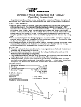
DIGITAL SIGNAL PROCESSING AND MODULATION
The preamplified and limited audio signal is converted to digital using a 24-bit A/D converter and fed to the DSP.
Within the DSP, the audio is encoded to reduce the bit rate and increase entropy in the data stream prior to encryp-
tion. The data stream is then encrypted and apportioned into packets, delimited by packet headers. The complete
bit stream is modulated onto the carrier using a modified pi/4 DQPSK (differential quadrature phase shift keying)
method. This modulation method makes efficient use of the RF spectrum and is easy to demodulate reliably.
Phase
Locked
Loop
Freq
Switches
11001001
A-D
Converter
Digital Signal Processor
Shunt
Limiter
Bicolor
Modulation
LEDs
Microprocessor
9V
Battery
Switching
Power
Supply
+3.3v
+1.8v
+9v
-3v
50
Isolator
Audio
Bicolor
Power
LED
Audio
Level
Input
Amp
LF
Rolloff
Digital
Modulator
RF
Amp
Dual
Envelope
Limiter
Encode Encrypt
Voltage
Controlled
Oscillator
Encryption
Key Link
Preamp
Mic
Element
Preamp
Level
Tone

4
UT700
LECTROSONICS, INC.
RF OUTPUT SECTION
Intermodulation (IM) occurs in the final amplifier stages of conventional transmitters when the transmitters are within
a few feet of each other. This can create serious problems in multichannel wireless systems when an IM signal falls
on the carriers, IF frequencies, local oscillator and image frequencies of the systems being operated. To eliminate
this problem in the UT700, the modulated radio signal passes through a circular isolator before entering the antenna.
The circular isolator functions like a “one-way check valve” to allow the RF signal to pass through to the antenna, but
not to pass backwards into the amplifier stage. RF signals from other nearby transmitters cannot reach the output
amplifier in the UT700. This provides excellent stability and eliminates IM in the output stage of the transmitter.
LONG BATTERY LIFE
High efficiency circuits and switching power supplies throughout the design allow over 4.5 hours of operation using a
single 9 Volt alkaline battery. (A 9V lithium battery will provide over 14 hours of operation.) The battery compartment
is a unique mechanical design which automatically adjusts to fit any brand of battery. The battery contacts are spring
loaded to prevent “rattle” as the unit is handled.
FREQUENCY AGILITY
700 Series wireless systems are available on eight different “blocks” of 256 frequencies, from 537.600 to 767.900
MHz. Each of these blocks provides 256 selectable frequencies in 100 kHz steps over a 25.6 MHz bandwidth. This
wide variety of selectable frequencies alleviates carrier interference problems in mobile or traveling applications. Two
16-position rotary switches on the side panel of the unit are used to select the frequency.
The UT700 transmitter section uses a synthesized, frequency selectable main oscillator The frequency is extremely
stable over a wide temperature range and over time.
ENCRYPTION SYSTEM
The 700 Series employs state-of-the-art 128-bit encryption for exceptional data security. (128-bit encryption means
there are 300 trillion, trillion, *trillion* possible keys, assigned with equal probability.) The system offers three levels
of security, trading off ease of use for immunity to attack.
LEVEL 1 offers the most intuitive operation. Once the key has been set, the equipment may be operated exactly the
same as a traditional analog system. The transmitter and receiver may be powered on in any sequence, and the
transmitter may move in and out of range without consequence (except normal squelching). Security in this mode is
excellent, but the scrambling sequence repeats approximately every 20,000 bits, theoretically exposing the user to
differential attacks. Due to its ease of use and quite effective security, level 1 is the default security level.
LEVEL 2 offers much greater encryption strength, at the cost of slightly less intuitive operation. In level 2, the
scrambling sequence never repeats (i.e. the PRNG is free-running), so the receiver must be on and ready to receive
when the transmitter is first switched on. Some signal loss is tolerated but if the transmitter should wander out of
range for more than ten seconds, it will be necessary to switch it off and on again to restart the sequence,
resynchronizing with the receiver. Security in this mode is a great deal stronger than level 1, since the scrambling
sequence never repeats. Only if the sequence is deliberately reused (i.e. by cycling transmitter power after prolonged
signal loss, or by reusing the same key session after session) is a differential attack possible even in theory.
LEVEL 3 offers the strongest encryption of all, again at the cost of some convenience. Level 3 is much like level 2,
except that the equipment itself enforces a policy that NO PORTION OF ANY SCRAMBLING SEQUENCE SHALL
EVER BE USED MORE THAN ONCE. This is a fundamental tenet of cryptography: key reuse leads to vulnerability.
Thus, level 3 security is about as close to the holy grail of the one-time pad as any wireless vendor is likely to offer at
a reasonable price. Operation is a little different in level 3:
• The transmitter starts sending immediately after receiving a key ONLY. It does not send when first powered on.
• Only one transmitter may receive each key.
• If the transmitter is out of range of the receiver for more than ten seconds, it will be necessary to generate a
new key in order to continue using the system.
All three levels offer strong encryption, so each user may make a policy decision based on an assessment of risk.
Those requiring ease of use may relax, knowing that eavesdropping is extremely difficult even in level 1. Many users
may find level 2 to be just as convenient, allowing them to use greater encryption strength. Those users willing to
follow stricter security procedures can use level 3, the strongest encryption available today from a wireless micro-
phone.

5
Digital Frequency Agile UHF Hand-held Transmitter
Rio Rancho, NM – USA
MICROPHONE ELEMENT
The UT400 includes the Lectrosonics VariMic mic element. The VariMic is a cardioid condenser back electret
microphone that is adapted for the unique circumstances of wireless microphones. The problems it solves are
dynamic range, handling noise and low frequency noise (rumble or wind).
In the VariMic, an unusual pumped source FET circuit increases the usable dynamic range 12dB and greatly reduces
distortion, just as if the FET were being supplied with 48 Volts. In addition, a unique 16 position sensitivity control at
the element itself can adjust the sensitivity in 15 steps over a 15 dB range. This is in addition to the normal gain
control in the wireless microphone. The result is the widest dynamic range of any condenser mic in a wireless
microphone.
The VariMic has a three point damped rubber suspension to reduce high frequency handling noise and a generous
sized windscreen to keep wind noise and breath pops away from the microphone.

6
UT700
LECTROSONICS, INC.
Encryption Key Link
Power Switch
Power LED
CONTROLS AND FUNCTIONS
“P” SWITCH – POWER ON/OFF
A slide switch (located on the outside bottom of the unit)
which turns battery power on and off.
The Power LED glows green when the battery is good and
the ON/OFF switch is ON. The lamp will glow red as the
battery voltage drops and finally flashes when there is
about 30 minutes of operation left with the recommended
alkaline battery. A NiMh battery will give little or no warning
when it is depleted. If you wish to use NiMh batteries in the
unit, we recommend trying fully charged batteries, noting
the length of time that the batteries will run the unit and in
the future use somewhat less than that time to determine
when the battery needs to be replaced. A weak battery will
sometimes light the POWER LED to the “good” green
indication immediately after being put in the unit, but will
soon discharge to the point where the LED will go red or
shut down, just like a flashlight with “dead” batteries. If the
lamp fails to light, the battery should be replaced.
ENCRYPTION KEY LINK
This jack is used to connect the transmitter to the receiver
to generate an encryption key. Since this handheld transmitter doesn’t have a mic connector, this jack is provided to
interconnect with the receiver using a special cable for key
generation. Please refer to the receiver manual for further
details.
LED POWERUP SEQUENCE
The UT700 is unique among 700 series transmitters in that
its audio LEDs are located under a cover and often aren’t
visible. Because of this, the blink code indicating the
current operating mode is issued using the power LED
instead of the audio LEDs.
LOCKED MODE
The UT700 can be placed in a locked mode where neither
the power switch nor the frequency switches have any
further effect on operation. This protects the unit from
accidental poweroff or misadjustment after it has been
prepared for use.
To enter locked mode, toggle the power switch off and on again rapidly three times. (Each toggle must take no longer
than two seconds and no more than ten seconds may elapse between successive toggles.) During the first two
toggles, the power LED will behave normally, blinking slowly red while the switch is in the off position to warn that the
power will go off, then returning to normal battery status indication when the switch is on again. After the third toggle,
the power LED will go out briefly, then blink the code that indicates the current mode (in red, indicating locked mode),
just as it does when the unit is first powered on. This blink code reprise (in red) serves as a confirmation that the
switches are now locked.
Locked mode can be cleared by removing the battery. Note that removing the battery bypasses the normal delayed
poweroff circuit, so it may cause noise at the receiver.
Audio Level LEDs
-20 -10
Frequency Switches
Coarse Fine
Audio Level

7
Digital Frequency Agile UHF Hand-held Transmitter
Rio Rancho, NM – USA
HIDING THE POWER LED
This unit has no provision for disabling the LEDs. The audio LEDs are covered
during normal use but the power LED is exposed. If the light is objectionable, we
recommend covering the LED with a piece of tape.
FREQUENCY ADJUST
Two rotary switches (located under the battery door) adjust the center frequency
of the carrier. The Coarse adjustment adjusts the frequency in 1.6 MHz steps
and the fine in 100 kHz steps. Each transmitter is factory aligned at the center of
its operating range for uniform operation across the entire band. The default
position of the frequency select switches is in the center of the transmitter range.
MOD LEVEL LEDs
These LEDs (located under the battery door) indicate the proper setting of the MIC LEVEL control. There are two
bicolor modulation LEDs that can light either red or green.
“-20dB level” One modulation LED glows green and the transmitter is 20 dB below full modulation.
“-10 dB level” Both modulation LEDs glow green and the transmitter is close to full modulation.
“+0 dB level” The -20 LED glows red and the -10 LED glows green. The transmitter is in slight limiting and is
fully modulated. This is probably desirable. See the discussion below under Input Limiter.
“+10 dB level” Both LEDs are red. The transmitter is in limiting and you may want to reduce the transmitter audio
gain. See the discussion below under Input Limiter.
INPUT LIMITER
The 700 series transmitters employ a digitally-controlled analog audio limiter just before the analog-to-digital con-
verter. The limiter has a range of more than 30dB for excellent overload protection. A dual release envelope makes
the limiter acoustically transparent while maintaining low distortion. It can be thought of as two limiters in series,
connected as a fast attack and release limiter followed by a slow attack and release limiter. The limiter recovers
quickly from brief transients, so that its action is hidden from the listener, but recovers slowly from sustained high
levels, to both keep audio distortion low and preserve short term dynamic changes.
The audio level LEDs indicate limiter activity. The first red LED indicates that the limiter is active and that the trans-
mitter is fully modulated (audio level is between +0 and +10 dB). The second red LED indicates that the level is
10dB or more into limiting. Occasional forays into the red are desirable for most applications, since the distortion
introduced by the limiter is so minimal, and full modulation is thus assured. We strongly recommend setting the gain
of the transmitter high enough so that the first red LED occasionally lights.
Generally speaking, some limiting is desirable in normal operation to improve the signal to noise ratio of the system.
The limiting action is not audible and does not create distortion. A highly trained ear would hear only the compres-
sion of the peaks in the audio signal, which is desirable with most recorders and many sound reinforcement systems.
AUDIO LEVEL
This knob (located under the battery door) is operated while speaking or singing into the transmitter to adjust the
audio gain of the transmitter for the correct amount of modulation. The LEDs located next to it indicate the modula-
tion level as the gain is adjusted. See the Operating Instructions section for details on this very important
adjustment.
Coarse Fine
8
9
A
B
C
D
E
F
0
1
2
3
4
5
6
7
8
9
A
B
C
D
E
F
0
1
2
3
4
5
6
7

8
UT700
LECTROSONICS, INC.
VARIMIC CONTROLS
Caution - Due to the high RF levels surrounding the
transmitter, the sound of the Varimic capsule may be
temporarily affected if the metal windscreen is not in
place. Always make the final decision about sound
balance and quality with the windscreen in place.
Preamp Level Control
Bass (LO) Mid (MID) Treble
(HI)
+10
0dB
-10
10Hz
100Hz
1KHz
10KHz
+5
-5
UT200 Bass/Midrange/Treble Boost/Cut
The VariMic head includes adjustments for Bass,
Midrange and Treble response. There is also an attenua-
tion adjustment to provide up to 15dB of additional head-
room if needed.
BASS / MID / TREBLE (LO / MID / HI)
The bass and treble controls will boost/cut by up to
approximately 8dB while the Mid control will boost/cut up
to about 6dB. These controls operate as standard tone
controls. Counter-clockwise will reduce the response in
that band and clockwise will provide a true boost. These
controls can be accessed by removing the windscreen.
To remove the windscreen, grasp the body of the trans-
mitter in one hand and the windscreen in the other hand.
Carefully unscrew the wind-screen counter-clockwise until
it comes off then carefully slide the windscreen past the
mic element.
• Set flat, the mic capsule is very wide range and sounds
a lot like a large competitor’s top line condenser mic.
• Bass cut gives a dry but highly intelligible sound. Crisp.
• Bass boost “fattens” the sound but is very listenable.
Does not get midbass boomy.
• Midrange cut sounds very smooth. Almost a “crooner”
quality. A sweet sound.
• Midrange boost is likely to be useful in a system that is
midrange shy.
• Treble cut has a “mellow” sound. The capsule has a
solid high end so a little cut does not ruin the response.
• Treble boost might be fine on some sound systems. The
sound doesn’t get harsh (showing that the response was
smooth) but sibilants are a little too much. Should be
used in moderation.
PREAMP LEVEL CONTROL
The VariMic head includes an attenuator to provide an
additional 15dB of headroom when needed. The attenua-
tor should only be used when the normal Mic Level pot is
already turned down as far as it will go and the signal
through the mic is still too hot. The attenuator control is a
16-position switch marked 0 through F. “F” is minimum
attenuation or the highest signal level. “0” is maximum
attenuation or the lowest signal level. For the maximum
amount of headroom, set the switch to “0.”

9
Digital Frequency Agile UHF Hand-held Transmitter
Rio Rancho, NM – USA
Note: The attenuator should not be used as a level control. The Audio Level control inside the battery
compartment is the main level control. Adjust the attenuator only when the Audio Level control is turned
completely down and more headroom is still needed. Be sure to set the attenuator back to its original setting for
normal operation.
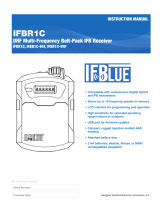
BASS FILTER
In addition to the tone controls, the UT700 also has a built in bass filter. This filter is fixed and cannot be adjusted or
defeated. Low frequency noise is much more of a problem with wireless microphones than with conventional micro-
phones. With a regular mic, low frequency wind noise, breath thumps or handling rumble can be filtered out at the
control board before the noise causes problems with the following electronics or speaker systems. But with a
wireless microphone, the electronics that will be overdriven are right in the wireless microphone. Filtering at the
control board is much too late. To solve this problem, the VariMic has a low frequency filter that is so sharp that it
can remove low frequency noise without affecting any wanted vocals. It consists of a 36 dB per octave filter circuit to
sharply remove low frequency noise below 75 Hz without affecting vocal fundamentals. The lowest operatic bass
voice fundamental is 82 Hz.
20
0dB
-20
-40
-60
10Hz
100Hz
1KHz
10KHz
VariMic Low Frequency Roll-off Filter
-3dB @ 71Hz
-20dB @ 50Hz

10
UT700
LECTROSONICS, INC.
BATTERY INSTALLATION
The transmitter is powered by a standard alkaline or lithium 9 Volt battery. It is important that you use ONLY an
ALKALINE or LITHIUM battery for longest life. Standard zinc-carbon batteries marked “heavy-duty” or “long-
lasting” are not adequate. Ni-cad rechargeable batteries will only provide 1.5 hours of operation, or less, and will
run down quite abruptly. Unless it is cold, alkaline batteries provide over 4.5 hours of operation. Lithium batteries
can be used to provide up to 14 hours. Care should be taken not to leave a fully discharged lithium battery in the
transmitter, as swelling of the battery can make it difficult to remove from the compartment. The battery status
circuitry is designed for the voltage drop over the life of alkaline batteries.
To open the battery compartment, press outward on the cover door in the direction of the arrow as shown in the
drawing. Only firm, sliding pressure is needed to open and close the battery door. Swing the door open and take
note of the polarity marked inside showing the location of the positive (+) and negative (-) terminals. You can see the
large and small contact holes inside the battery compartment with the door open.
Insert the battery correctly and close the cover by pressing the door closed and across, reversing the opening
procedure illustrated above. If the battery is inserted incorrectly, the door will not close. Do not force the door
closed.
P
P
+
–
+
–
Pull Ring
Outward
Rotate Ring
1/8 Turn
Remove
Cover
Insert
Battery
Rotate Ring To
Lock Closed
Replace
Cover
Ring will sit flush in the
closed position.
Depress the plunger with
the corner of the battery
and slide the battery into
the compartment. Note that
the locking ring is in the
closed position for this
procedure.
Alternate Method
STEP 1
STEP 2
STEP 3
STEP 4
STEP 5
STEP 6

11
Digital Frequency Agile UHF Hand-held Transmitter
Rio Rancho, NM – USA
OPERATING INSTRUCTIONS
ADJUSTING THE GAIN
1) Install a fresh battery. Leave the battery cover off for further adjustment.
2) On the bottom panel, move the “P” (power) switch to ON, toward the LED. Observe that the battery status LED is
glowing green indicating a good battery. If the LED is glowing red, replace the battery.
Note: If the security level is set to “2”, the receiver must be powered on before the transmitter.
If the security level is set to “3”, communications do not begin until a fresh key is transfered.
3) Hold the microphone in the same position that it will be used in actual operation.
4) While speaking or singing
at the same voice level that will actually be used, observe the MODULATION LEDs.
Adjust the AUDIO LEVEL control knob until the LEDs begin to light. At too low a setting neither LED will light as
you speak. Gradually, turn the gain up until the –20 dB LED lights green and then the -10 dB lights green. We
strongly recommend setting the gain of the transmitter even higher so that the first red LED occasionally lights.
If you find that the AUDIO LEVEL control is set to minimum and the LIMIT LED is still on often, then adjust the
preamp level control. This control is located under the windscreen. Unscrew the windscreen and carefully lift it
off the top of the unit. See the VERIMIC CONTROLS section for these adjustments. If you need to change these
controls, be sure to repeat the gain adjustment procedure beginning at step 3.
5) Once the gain has been adjusted, the audio system audio can be turned on to make level adjustments in the
main audio system.
SETTING THE ENCRYPTION KEY
Please refer to the receiver manual for instruction on setting the encryption key.
OPERATING NOTES
The AUDIO LEVEL control knob should not be used to control the volume of your sound system or recorder levels.
This gain adjustment matches the transmitter gain with the user’s voice level and microphone positioning.
If the audio level is too high — both red LEDs will light frequently or stay lit. This condition may reduce the dynamic
range of the audio signal.
If the audio level is too low — neither LED will light, or only the -20 LED will light green. This condition may cause
hiss and noise in the audio.
Different voices will usually require different settings of the AUDIO LEVEL control, so check this adjustment as each
new person uses the system. If several different people will be using the transmitter and there is not time to make
the adjustment for each individual, adjust it for the loudest voice.
ADJUSTING THE TRANSMITTER FREQUENCY
If you are experiencing interference from another signal on your frequency, you
may want to change the operating frequency of your system. The left switch
changes the operating frequency by 1.6 MHz per step and the right switch
changes it 100 kHz per step. If you are experiencing interference, change the
operating frequency in 100 kHz steps to find a clear channel. If it is not possible
to find a clear channel using the 100 kHz switch, return it to its original position
and change the 1.6 MHz switch by one click then try the 100 kHz switch again.
To gain access to these switches, slide the access door sideways with a finger-
nail.
The UDR700 receiver front panel will indicate the correct switch settings to match the receiver frequency.
Coarse Fine
8
9
A
B
C
D
E
F
0
1
2
3
4
5
6
7
8
9
A
B
C
D
E
F
0
1
2
3
4
5
6
7

12
UT700
LECTROSONICS, INC.
TROUBLESHOOTING
Before going through the following chart, be sure that you have a good battery in the transmitter. It is important that
you follow these steps in the sequence listed.
SYMPTOM POSSIBLE CAUSE
TRANSMITTER BATTERY LED OFF 1) Battery is inserted backwards.
2) Battery is dead, or too low to be used.
NO TRANSMITTER MOD LEVEL LEDs 1) Gain control turned all the way down.
2) Battery is in backwards. Check power LED.
3) Mic capsule is damaged or malfunctioning. Contact the
factory for repair.
RECEIVER RF LAMP OFF 1) Transmitter not turned on.
2) Transmitter battery is dead.
3) Receiver antenna missing or improperly positioned.
4) Transmitter and receiver not on same frequency. Check labels
on transmitter and receiver and the frequency switch settings.
5) Operating range is too great.
NO SOUND BUT RECEIVER AUDIO LEVEL
METER INDICATES 1) Receiver audio is muted or set too low.
2) Receiver audio output is disconnected or cable
defective or mis-wired.
3) Sound system or recorder input is turned down.
DISTORTED SOUND AND/OR
MOTORBOATING 1) Transmitter gain (audio level) is too high. Speak or sing into
the transmitter and check mod level lamps on transmitter and
receiver.
2) Receiver output level may be too high for the sound
system or recorder input.
3) Excessive wind noise or breath “pops.” Microphone
may require an additional wind screen.
4) Transmitter frequency switches mis-set.
5) RF feedback getting into VariMic mic capsule. Ensure that the
windscreen is present and screwed down snugly.
HISS AND NOISE -- AUDIBLE DROPOUTS 1) Transmitter gain (audio level) too low.
2) Receiver antenna missing or obstructed.
3) Operating range too great.
4) Transmitter frequency switches mis-set.
EXCESSIVE FEEDBACK 1) Transmitter gain (audio level) too high. Check gain adjustment
and/or reduce receiver output level.
2) Microphone too close to speaker system.
3) Move microphone closer to the user’s mouth, and lower the
sound system volume.

13
Digital Frequency Agile UHF Hand-held Transmitter
Rio Rancho, NM – USA
MICROPHONE HAS A “WHINE” NOISE IN 1) Install bypass capacitors at both ends of the mic cable
THE BACKGROUND WHICH VARIES AS THE use the factory supplied microphone.
MIC CABLE IS MOVED
RECEIVER OUTPUTS AN EXTREMELY LOUD, 1) Encryption keys in transmitter and receiver do not match.
HISSY, SWISHY SOUND Refer to receiver manual to choose a new key and send it
to the transmitter.
NO AUDIO OUTPUT, AUDIO LEDS BLINK IN 1) System is in security level 3 and is not synchronized.
SEQUENCE, LED DISPLAY SHOWS to correct this in security level 2, turn the transmitter off
“POWER TX OFF+ON” OR “NEW KEY REQUIRED” then on again. In level 3, a new key must be generated.
SECURITY FEATURES DIFFERENT FROM 1) This manual applies only to UDR700 version 3.0/3.0 and
THE DOCUMENTATION higher.

14
UT700
LECTROSONICS, INC.
SPECIFICATIONS AND FEATURES
Operating principle: Proprietary digital modulation with encryption
Modulation type: Modified pi/4 DQPSK
Sample rate: 44.1 ksps
Audio coder: Proprietary sub-band ADPCM
Encryption key length: 128 bit (300 trillion trillion trillion keys)
Bit rate: 220,500 bps including packet overhead
Operating frequencies: 537.600 to 793.500 MHz depending upon local regulations
Frequency selection: 256 frequencies in 100kHz steps
RF Power output: 50 mW (nominal)
Frequency stability: ± 0.001%
Equivalent input noise: –119 dBV, A-Weighted
Spurious radiation: 70 dB below carrier
Input Level: Nominal 2 mV to 300 mV before limiting
Greater than 1V maximum with limiting
Input compressor: Dual-envelope limiter; 30 dB range
Gain control range: 43 dB; semi-log rotary control
Modulation indicators: Dual multi-color LEDs indicate modulation level in 4 steps at
-20, -10, 0, +10 dB with green and red indications
Low frequency roll-off
adjustment: –18dB/octave; 35Hz to 150Hz
Controls: 2 position “ON-OFF” slide switch. Knob in battery compartment adjusts audio gain.
Rotary switches in battery compartment adjust transmitter frequency.
Battery: Precision compartment auto-adjusts to accept any known alkaline 9 Volt
battery. (We’ve tried 246 different ones!)
Battery Life: 3.5 hours (alkaline); 6.5 hours (lithium)
Weight: 12.4 ozs. with VeriMic capsule and lithium battery
Dimensions: 9” long, x 2.05” diameter at largest point with VeriMic capsule
Emission Designator: 180KQ2E
System Specifications
Audio frequency response: 40Hz to 20kHz, +/- 1dB
Audio dynamic range: >100 dB before limiting
Audio Distortion: 0.05% THD + noise at 1kHz
Specifications subject to change without notice.

15
Digital Frequency Agile UHF Hand-held Transmitter
Rio Rancho, NM – USA
SERVICE AND REPAIR
If your system malfunctions, you should attempt to correct or isolate the trouble before concluding that the equipment
needs repair. Make sure you have followed the setup procedure and operating instructions. Check out the intercon-
necting cords and then go through the TROUBLE SHOOTING section in the manual
We strongly recommend that you do not try to repair the equipment yourself and do not have the local repair shop
attempt anything other than the simplest repair. If the repair is more complicated than a broken wire or loose con-
nection, send the unit to the factory for repair and service. Don’t attempt to adjust any controls inside the units.
Once set at the factory, the various controls and trimmers do not drift with age or vibration and never require read-
justment. There are no adjustments inside that will make a malfunctioning unit start working.
LECTROSONICS service department is equipped and staffed to quickly repair your equipment. In-warranty repairs
are made at no charge in accordance with the terms of the warranty. Out of warranty repairs are charged at a
modest flat rate plus parts and shipping. Since it takes almost as much time and effort to determine what is wrong
as it does to make the repair, there is a charge for an exact quotation. We will be happy to quote approximate
charges by phone for out of warranty repairs.
RETURNING UNITS FOR REPAIR
You will save yourself time and trouble if you will follow the steps below:
A. DO NOT return equipment to the factory for repair without first contacting us by letter or by phone. We need to
know the nature of the problem, the model number and the serial number of the equipment. We also need a phone
number where you can be reached 8 am to 4 pm (Mountain Standard Time).
B. After receiving your request, we will issue you a return authorization number (R.A.). This number will help speed
your repair through our receiving and repair departments. The return authorization number must be clearly shown
on the outside of the shipping container.
C. Pack the equipment carefully and ship to us, shipping costs prepaid. If necessary, we can provide you with the
proper packing materials. UPS is usually the best way to ship the units. Heavy units should be “double-boxed” for
safe transport.
D. We also strongly recommend that you insure the equipment, since we cannot be responsible for loss of or damage
to equipment that you ship. Of course, we insure the equipment when we ship it back to you.
Mailing address: Shipping address: Telephones:
Lectrosonics, Inc. Lectrosonics, Inc. Regular: (505) 892-4501
PO Box 15900 581 Laser Rd. Toll Free (800) 821-1121
Rio Rancho, NM 87174 Rio Rancho, NM 87124 FAX: (505) 892-6243
USA USA
World Wide Web: http://www.lectrosonics.com Email: sales@lectrosonics.com

LECTROSONICS, INC.
581 LASER ROAD
RIO RANCHO, NM 87124 USA
www.lectrosonics.com
February 12, 2004
LIMITED ONE YEAR WARRANTY
The equipment is warranted for one year from date of purchase against defects in
materials or workmanship provided it was purchased from an authorized dealer. This
warranty does not cover equipment which has been abused or damaged by careless
handling or shipping. This warranty does not apply to used or demonstrator equipment.
Should any defect develop, Lectrosonics, Inc. will, at our option, repair or replace any
defective parts without charge for either parts or labor. If Lectrosonics, Inc. cannot
correct the defect in your equipment, it will be replaced at no charge with a similar new
item. Lectrosonics, Inc. will pay for the cost of returning your equipment to you.
This warranty applies only to items returned to Lectrosonics, Inc. or an authorized
dealer, shipping costs prepaid, within one year from the date of purchase.
This Limited Warranty is governed by the laws of the State of New Mexico. It states the
entire liablility of Lectrosonics Inc. and the entire remedy of the purchaser for any
breach of warranty as outlined above. NEITHER LECTROSONICS, INC. NOR
ANYONE INVOLVED IN THE PRODUCTION OR DELIVERY OF THE EQUIPMENT
SHALL BE LIABLE FOR ANY INDIRECT, SPECIAL, PUNITIVE, CONSEQUENTIAL,
OR INCIDENTAL DAMAGES ARISING OUT OF THE USE OR INABILITY TO USE
THIS EQUIPMENT EVEN IF LECTROSONICS, INC. HAS BEEN ADVISED OF THE
POSSIBILITY OF SUCH DAMAGES. IN NO EVENT SHALL THE LIABILITY OF
LECTROSONICS, INC. EXCEED THE PURCHASE PRICE OF ANY DEFECTIVE
EQUIPMENT.
This warranty gives you specific legal rights. You may have additional legal rights which
vary from state to state.
LIMITED ONE YEAR WARRANTY
/