Page is loading ...


UHF Digital Hybrid Wireless® Receiver
Rio Rancho, NM 3
Digital Hybrid WirelessTM
The Lectrosonics Digital Hybrid WirelessTM uses in-
novative technology to combine the new advantages of
digital audio with the advantages of analog RF trans-
mission, thus delivering the superior sound quality of a
digital system and the excellent range of an analog sys-
tem. A proprietary algorithm encodes the digital audio
information into an analog format which can be trans-
mitted in a robust manner over an analog FM wireless
link. The receiver employs state-of-the-art filters, RF
amplifiers, mixers and detector to capture the encoded
signal and a DSP recovers the original digital audio.
This digital/analog hybrid technique has some very
beneficial properties. Because the information being-
transmitted is digitally encoded, immunity to noise is
much higher than a compandor can offer. Because the
encoded audio is sent in analog format, spectral and
power efficiency and operating range are not compro-
mised.
Under weak RF conditions, the received signal de-
grades gracefully, like an analog system, delivering
as much usable audio as possible at maximum range.
Since the audio is free of compandor artifacts, pumping
and breathing problems are also greatly reduced.


UHF Digital Hybrid Wireless® Receiver
Rio Rancho, NM 5
Table of Contents
General Technical Description ..............................................................................................................................................................7
Diversity Reception ...............................................................................................................................................................................7
MIicrocontroller, PLL and VCO Circuits.................................................................................................................................................7
IF Amplifiers and SAW Filters ...............................................................................................................................................................8
Digital Pulse Counting Detector ............................................................................................................................................................8
DSP-Based Pilot Tone ...........................................................................................................................................................................8
Smart Squelch™ .......................................................................................................................................................................................................................................................................................................................8
Smart Noise Reduction (SmartNR™) ....................................................................................................................................................8
Supersonic Noise-Based Dynamic Filter and Squelch .........................................................................................................................9
RF-Controlled Digital Noise Filter .........................................................................................................................................................9
Audio Output Level ...............................................................................................................................................................................9
Test Tone ...............................................................................................................................................................................................9
Batteries ................................................................................................................................................................................................9
Power Supply ........................................................................................................................................................................................9
LCD Display ..........................................................................................................................................................................................9
Power Up Sequence .............................................................................................................................................................................9
Power Off ..............................................................................................................................................................................................9
Front Panel Controls and Functions ...................................................................................................................................................10
LCD Screen ........................................................................................................................................................................................10
MENU Button ......................................................................................................................................................................................10
SELECT Up/Down Buttons .................................................................................................................................................................10
Power ON/OFF Switch ........................................................................................................................................................................10
Rear Panel Features .............................................................................................................................................................................10
XLR Audio Output Jack .......................................................................................................................................................................10
Power Input Jack .................................................................................................................................................................................10
Main Window (LCD) ..............................................................................................................................................................................11
Menu Selections from Main Window ...................................................................................................................................................12
Frequency Window..............................................................................................................................................................................12
Battery Level Window .........................................................................................................................................................................12
Setup Window .....................................................................................................................................................................................13
LEVEL .................................................................................................................................................................................................13
TONE ..................................................................................................................................................................................................13
TXBAT .................................................................................................................................................................................................13
PHASE ................................................................................................................................................................................................13
SmtNR ................................................................................................................................................................................................13
TUNING ..............................................................................................................................................................................................14
COMPAT .............................................................................................................................................................................................14
Frequency Scan Mode .........................................................................................................................................................................15
Scan & View Window Elements ..........................................................................................................................................................15
Fine View Window Elements ...............................................................................................................................................................15
Antenna Use and Placement ...............................................................................................................................................................16
Setup and Operating Instructions .......................................................................................................................................................17
Installing/Replacing Batteries..............................................................................................................................................................17
Adjusting Audio Output .......................................................................................................................................................................17
Finding Clear Frequencies ..................................................................................................................................................................18
Locking and Unlocking the UCR401 ...................................................................................................................................................19
Pre-coordinated Frequencies ..............................................................................................................................................................20
Compatible Frequency Table ...............................................................................................................................................................20
Compatibility Diagram .........................................................................................................................................................................21
Diagnostics ...........................................................................................................................................................................................22
Multi-channel System Checkout..........................................................................................................................................................22
Pilot Tone Bypass ................................................................................................................................................................................22
Replacement Parts and Accessories ..................................................................................................................................................23
Troubleshooting ....................................................................................................................................................................................24
Specifications and Features ................................................................................................................................................................26
Service and Repair ...............................................................................................................................................................................27
Returning Units for Repair ..................................................................................................................................................................27


UHF Digital Hybrid Wireless® Receiver
Rio Rancho, NM 7
The UCR401 is a portable, high performance, triple-
conversion, frequency synthesized, UHF receiver fully
compatible with all Lectrosonics 400 Series transmit-
ters, Lectrosonics wideband UHF analog systems. DSP
compatibility modes also provide compatibility with
some other transmitter brands. The RF performance is
extremely stable over a very wide temperature range,
making the UCR401 perfectly suited to the rough
environmental conditions found in field production. The
combination of digital audio with analog RF produces
superb audio quality and extended operating range.
The UCR401 front panel features a menu-driven LCD
interface and three control buttons to conveniently view
and alter user settings. The main LCD window simulta-
neously displays the pilot tone indicator, phase diversity
activity, RF level, audio level, battery status for both
transmitter and receiver. It is also possible to bypass
the pilot tone squelch from the main display window for
diagnostic purposes. Other windows display operating
frequency, audio output level, battery voltage and test
tone status.
A built-in spectrum analyzer scans across the tuning
range of the receiver to locate RF signals in the vicinity
and find clear operating frequencies.
Diversity Reception
Microprocessor controlled antenna phase combining
keeps the receiver small, with low power consumption,
yet it is still able to deal effectively with multi-path drop-
outs. SmartDiversity™ analyzes both the incoming RF
level and the rate of change in RF level to determine the
optimum timing for phase switching, and the optimum
antenna phase. This adaptive technique operates over
a wide range of RF levels to anticipate dropouts before
they occur. The system also employs “opportunistic
switching” to analyze and then latch the phase in the
best position during brief squelch activity.
RF Front-End and Mixer
The UCR401 is frequency agile and can be set to
operate on any one of 256 frequencies within its tuning
range. To significantly reduce unwanted interference
and intermodulation problems, the UCR401’s front-end
is tuned to the desired frequency band and rejects or
“tunes out” unwanted out-of-band signals. Two tuned
HI-Q ceramic transmission line resonators prior to a low
noise, high current RF amplifier provide good selectiv-
ity. A LC bandpass filter after the RF amplifier provides
added insurance against strong RF interference, and
the first mixer has a very high third order intercept point.
The overall design ensures stability, selectivity and pre-
cise gain in order to handle strong RF signals without
input overload.
MIicrocontroller, PLL and VCO Circuits
The 8-bit microprocessor is truly the “heart” of the
UCR401 receiver. It monitors user command inputs
from the front panel control buttons and numerous other
internal signals such as RF level, audio levels, pilot tone
levels and external/internal power voltages. Outputs
from the microcontroller drive the LCD display and
backlight, control the squelch and audio output attenu-
ator, and operate the front-end tuning, the PLL/VCO
circuits and the antenna phase switch. The UCR401
design and the advanced technology of the micropro-
cessor control arguably set a new standard in wireless
microphone development.
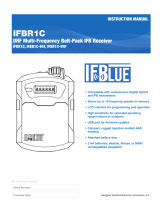
General Technical Description
2 (HI)
1 (COMMON)
3 (LO)
50
50
5K
5K
uP
LCD
Display
Panel
PILOT TONE
DETECT
FILTER
DIGITAL SIGNAL
PROCESSOR
Attenuation
CERAMIC
FILTER
2ND
MIXER
10.7 MHZ
SAW
FILTER
244 MHz
IF AMP
A-D
CONVERTER
D-A
CONVERTER
AMP
2nd
VCO
XLR
OUT
HI-LEVEL
MIXER
RF MODULE
3RD MIXER
AND
IF AMP
50KHz
LP FILTER
XTAL
CONTROLLED
3rd
OSCILLATOR
SAW
FILTER
244 MHz
IF AMP
COUNTING
DETECTOR
AUDIO
AMP
UCR401
BLOCK DIAGRAM
ANTENNA
COMBINING
FILTER
E PROM
2
1st
VCO
Smart Diversity
FILTER
PLL
SYNTHESIZER
LC
Filter
Output
Level
Adjust
Digital
Attenuator

UCR401
LECTROSONICS, INC.
8
incorporates recent squelching history and recent signal
strength, adjusting squelching behavior dynamically for
the most serviceable result under variable conditions.
Using these and other techniques, the UCR401 can
deliver acceptable audio quality from otherwise unus-
able signals.
Smart Noise Reduction (SmartNR™)
Note: The SmartNR setting is user selectable
only in 400 Series mode. In other modes, noise
reduction is applied in such a way as to emulate
the original analog system as accurately as
possible and is not user adjustable.
The UCR401 has been meticulously designed using the
best available low noise components and techniques.
Nonetheless, the wide dynamic range of digital hybrid
technology, combined with flat response to 20 kHz,
makes it possible to hear the -120 dBV noise floor in
the mic preamp, or the (usually) greater noise from the
microphone itself. To put this in perspective, the noise
generated by the recommended 4 k bias resistor of
many electret lavaliere mics is –119 dBV and the noise
level of the microphone’s electronics is much higher. In
order to reduce this noise the UCR401 is equipped with
a Smart Noise Reduction algorithm, which removes
hiss without sacrificing high frequency response.
The Smart Noise Reduction algorithm works by at-
tenuating only those portions of the audio signal that fit
a statistical profile for randomness or “electronic hiss.”
Because it isn’t simply a sophisticated variable low pass
filter as in Lectrosonics’s 195 and 200 series analog de-
signs, much greater transparency is obtained. Desired
high frequency signals having some coherence are not
affected, such as speech sibilance and tones.
The Smart Noise Reduction algorithm has three modes,
selectable from a user setup screen: OFF, NORMAL,
and FULL. When switched OFF, no noise reduction is
performed and complete transparency is preserved. All
signals presented to the transmitter’s analog front end,
including any faint microphone hiss, will be faithfully
reproduced at the receiver. When switched to NORMAL,
enough noise reduction is applied to remove most of
the hiss from the mic preamp and some of the hiss from
lavaliere microphones. The noise reduction benefit is
significant in this position, yet the degree of transparen-
cy maintained is exceptional. When switched to FULL,
enough noise reduction is applied to remove most of
the hiss from nearly any signal source of reasonable
quality, assuming levels are set properly at the transmit-
ter, and some high frequency environmental noise. The
optimal setting for each application is subjective and
selected while simply listening.
IF Amplifiers and SAW Filters
The first IF stage at 244 MHz employs two state-of-the-
art SAW (surface acoustic wave) filters. The use of two
filters significantly increases the depth of filtering while
preserving sharp skirts, constant group delay, and wide
bandwidth. Though expensive, this special type of filter
allows primary filtering as early as possible, at as high a
frequency as possible before high gain is applied to the
signal for maximum image rejection.
Since these filters are made of quartz, they are very
temperature stable. After the SAW filter, the 244 MHz IF
signal is converted to 10.7 MHz IF and then to the low
frequency of 300 kHz. Only then is the majority of the
gain applied, just before the signal is converted to audio
with a pulse counting detector. Although 300 kHz is very
unconventional for an IF in a wide deviation (±75 kHz)
system, it offers outstanding AM rejection figure over
a very wide range of signal strengths and produces an
excellent noise improvement at low signal strengths.
Digital Pulse Counting Detector
The UCR401 receiver uses an elegantly simple, yet
highly effective digital pulse detector to demodulate
the FM signal, rather than a conventional quadrature
detector. This unusual design eliminates thermal drift,
improves AM rejection, and provides very low audio
distortion.
DSP-Based Pilot Tone
The Digital Hybrid system design uses a DSP gener-
ated ultrasonic pilot tone to control the receiver audio
muting (squelch). Brief delays are applied to eliminate
thumps, pops or other transients that can occur when
the power is turned on or off. The pilot tone frequency
is different for each of the 256 frequencies in the tuning
range of a system (frequency block). This eliminates
squelch problems in multichannel systems where a
pilot tone signal can appear in the wrong receiver via
intermodulation products. The DSP generated pilot tone
also eliminates fragile crystals, allowing the receiver to
survive shocks and mishandling much better than older
analog-based pilot tone systems.
Note: This description applies only in 400 Series
mode. In 200 Series mode, only one pilot tone
frequency is used on all channels, emulating
the original crystal-based system. In other
compatibility modes, no pilot tone is used.
Smart Squelch™
Any squelching system faces inevitable trade-offs:
squelch too aggressively and valuable audio information
may be lost. Squelch too little and excessive noise may
be heard. Respond too rapidly and the audio will sound
“choppy.” Respond too sluggishly and syllables or entire
words can be cut off.
The UCR401 combines several techniques to achieve
an optimal balance, removing distracting noise, without
the squelching action itself becoming a distraction. One
of these techniques involves waiting for a word or syl-
lable to complete before squelching. Another technique

UHF Digital Hybrid Wireless® Receiver
Rio Rancho, NM 9
Supersonic Noise-Based
Dynamic Filter and Squelch
In addition to SmartNR, all hybrid receivers are
equipped with a supersonic noise-based dynamic filter
and squelch system. The incoming audio is monitored
for energy above 22 kHz, pilot tone excepted. Excessive
high frequency energy indicates that the received signal
is too weak to achieve an acceptable signal-to-noise
ratio. Under marginal conditions, a variable low pass
filter is rolled in dynamically, masking the noise while
preserving as much of the transmitted signal as pos-
sible. When the channel is too noisy even for the filter,
the audio is squelched.
This noise-based filter and squelch system replaces a
more or less equivalent system used for many years,
which based its operation on RF signal strength. Perfor-
mance of the two systems is virtually identical, but the
noise-based system requires no calibration and there
is no better way to track the signal-to-noise ratio than to
measure it directly.
RF-Controlled Digital Noise Filter
In extremely weak signal conditions, an RF sensitive
variable frequency filter is applied to reduce the high
frequency response of the receiver. This filter does
nothing until the RF signal strength drops below 3 uV at
which point it begins to roll off high frequencies. Usable
audio remains unaffected, but noise-ups or “hits” occur-
ring near the fringe of reception sound much less harsh.
Audio Output Level
A setup screen is provided for adjusting the audio out-
put level in 1 dB increments from -50 to +5 dBu using
the front panel SEL Up and Down buttons.
Test Tone
To assist in matching the audio levels of equipment con-
nected to the UCR401, a 1 kHz audio test tone, adjust-
able from -50 to +5 dBu in 1 dB increments, is available
at the XLR connector. This tone is available through the
TONE display window.
Batteries
The UCR401 operates on two AA 1.5 Volt alkaline,
lithium or NiMH batteries. Access to the battery com-
partment is gained by lifting one end and turning the
rear panel door.
Note: Do not mix battery types in the same unit.
Also, standard or “heavy duty” batteries are not
recommended.
Power Supply
The UCR401 may be operated from an external DC
power source. The power supplies are protected from
damage to the receiver that could occur if a positive
ground power source is applied.
LCD Display
The display has four primary windows. Pressing the
Front Panel MENU button steps through each of these
windows.
If the battery gets low on either transmitter or receiver,
a message will interrupt the display every few seconds
and flash a low battery warning.
After power is turned off and back on again, the unit
defaults to the main window and to the most recent fre-
quency, audio level, transmitter battery type and other
user settings. These settings are retained even if the
batteries are removed. After five minutes of no key ac-
tivity, the LCD backlight goes off and the display reverts
back to the main window.
Power Up Sequence
The power up sequence consists of four messages that
appear automatically after the power is switched on.
1) UCR401
BLK xx (xx is the frequency block number)
2) VERSION
R.R/A.A (R.R is the RF board firmware version,
A.A is the audio board firmware version)
3) COMPAT
mode (mode is one of the following:
400 - Native 400 Series mode
100 - Lectro 100 Series compatibility
200 - Lectro 200 Series compatibility
MODE 3 - compatible with certain
non-Lectrosonics transmitters)
IFB - compatible with all Lectrosonics IFB
transmitters.
MODE 6 - compatible with certain
non-Lectrosonics transmitters)
4) TUNING
mode (mode is one of the following:
NORMAL - tune in single channel increments
GRP x - tune in precoordinated intermod-free
frequencies (x is A, B, C, D, U or V))
The Main Window appears after the introductory mes-
sages are displayed.
The UCR401 is fully operational during the power
up sequence and will immediately respond to button
pushes made before the automatic sequence is com-
pleted. If a valid transmitter signal is already present
when the receiver is turned on, the audio output will
typically be engaged somewhere in the middle of the
power-up sequence, following a brief delay to allow the
audio circuits to stabilize.
Power Off
When the Front Panel Power ON/OFF switch is moved
to the OFF position, the audio output is instantly muted
(squelched) and the message “POWERING OFF...” is
displayed briefly before the receiver switches off.

UCR401
LECTROSONICS, INC.
10
Velcro Strain Relief
Front Panel Controls and Functions
LCD Screen
The LCD Screen is a graphics-type Liquid Crystal
Display that is used to monitor system operation and
configure the UCR401.
MENU Button
The MENU button steps through the four primary win-
dows and setup screens.
SELECT Up/Down Buttons
The SELECT Up/Down buttons are used to select vari-
ous options within each display selection and for setting
the operating frequency of the receiver.
Power ON/OFF Switch
The Power ON/OFF switch is used to apply battery or
external power to the unit.
XLR Audio Output Jack
This is a standard XLR configuration with pin 2 “posi-
tive” with reference to handheld and plug-on transmit-
ters. With lavaliere microphones and belt-pack transmit-
ters, however, phase will vary with different types of
microphones (2-wire versus 3-wire for example). The
audio output is balanced but not floating, so an unbal-
anced signal is available using pin 1 as ground and pin
2 as signal, leaving pin 3 open.
Power Input Jack
The power input jack can accept 6-18 VDC - the center
pin is positive and sleeve is ground. The input is diode
protected to prevent damage if the power is applied
with reversed polarity, but the unit will not work until the
reversed polarity condition is fixed. The jack and plug
feature twist-lock retention. The Power Input Jack will
also accommodate non-locking plugs.
Rear Panel Features
AUDIO OUT Jack Power Input Jack
Note: The external power source must have its
own short-circuit protection
Strain relief to avoid accidental disconnection can
be provided with the included small hook and loop
strip. Attach the adhesive strip side to the side of
the receiver or mount with
the opening end of the
strip up - place the cable
in the strip and secure.
SEL Down Button
SEL Up Button
MENU Button
Power OFF/ON Switch
LCD

UHF Digital Hybrid Wireless® Receiver
Rio Rancho, NM 11
SEL Down Button -
control down one step
SEL Up Button - control up
one step
MENU Button - changes
windows
Power ON/OFF switch
RF levels - reference for RF level screen icon
Audio Levels - reference levels
for audio signal modulation from
transmitter
Main Window (LCD)
The Main Window displays information concerning the
condition of the Pilot Tone, antenna phase, RF and
audio signal levels and battery conditions for both the
receiver and the associated transmitter. It is also the
access portal to menu selections for setting up the re-
ceiver and searching for clear frequency channels. (See
Menu Selections from Main Window and Frequency
Scan Mode.)
Pilot Tone Indicator
A steady “P” icon will be displayed when a pilot tone from the transmitter is present. The “P” will ap-
pear only in those compatibility modes which use pilot tone: 200 Series and the native 400 Series
modes, plus Mode 6. The icon will flash if no pilot tone is detected and will change to a small “b” if the
pilot tone has been bypassed. To bypass the pilot tone, hold MENU and press the UP button. Hold
MENU and press UP again to restore normal pilot tone squelch. Bypassing the pilot tone also dis-
ables the squelch, so the “pilot tone bypass” function has an effect even in those compatibility modes
that do not use pilot tone.
Antenna Phase Indicator
This icon shows antenna phase switching activity. As the antenna phase is switched, the symbol will
flip vertically.
RF Level
This icon changes in size vertically to indicate the strength of the incoming RF signal. RF levels are
engraved on a scale from 1uV to 1000uV on the bezel to the left of the LCD display.
Audio Levels
This icon changes in size horizontally to indicate the audio level (modulation) of the signal received
from the transmitter. The icon display will change to a solid rectangular block when the audio signal is
being limited in the transmitter. Levels in dB are engraved into the bezel above the LCD display.
Battery Levels
The icon above the Rx symbol indicates the receiver battery condition and will flash when approxi-
mately one hour of operating time is remaining. When external power is being used, the Rx battery
icon changes to look like a power plug. The area above the Tx symbol features either a transmitter
battery status icon or the transmitter battery timer, depending on the TXBAT setting. The transmitter
battery status icon is available only in compatibility modes supporting battery telemetry (400 and 200
Series). In such cases, the transmitter battery status icon appears 5 to 10 seconds after the transmit-
ter signal is acquired. If selected in the TXBAT setup screen, the transmitter battery timer is available
in any compatibility mode. It accumulates hours and minutes that the communications link is active,
retaining the timing even when the receiver is off.
Note: To reset the battery timer, press and hold MENU and SELECT Down together for one second.
Icon Description

UCR401
LECTROSONICS, INC.
12
Frequency Window
TVxx - The television broadcast channel the frequency
falls within.
Transmitter switch settings (AE
in the illustration) - These are the
correct settings for the frequency
switches on your transmitter - see
your transmitter instructions.
Frequency - Press the SEL Up and
Down buttons to change the frequency of the receiver.
Note: Be certain to change the transmitter
frequency switches to match the settings shown
in the upper right hand corner of the Frequency
window.
Menu Selections from Main Window
When the TUNING mode is set to NORMAL, the SEL
Up and Down buttons tune in single channel incre-
ments. In the GROUP tuning modes, the SEL Up and
Down buttons move among the selected intermod-free
frequencies.
Battery Level Window
This window shows the trans-
mitter (TX) and receiver (RX)
battery voltage. These levels will
flash when the voltages drop be-
low suggested optimum working
levels. Typically, there will be about one hour operating
time remaining after the indicators begin to flash. The
RX voltage changes to EX when operating on external
power and displays the external power source voltage.
(Disclaimer: We cannot guarantee 0.1 Volt accuracy.)
Frequency
Scan Mode
SELECT
Lock/Unlock
Pilot Off/On
Battery Level
Window
Frequency
Window
Main Window
P
r
e
s
s
M
E
N
U
P
r
e
s
s
M
E
N
U
P
r
e
s
s
M
E
N
U
P
r
e
s
s
M
E
N
U
Hold MENU & press UP
Press All Buttons
Press & Hold MENU
Press UP
Press
UP
Press UP
Press MENU
Setup Window
(Press UP / DOWN to adjust)
Level
Audio Te st To ne
Press MENU
(Press UP / DOWN to adjust)
Press MENU
Press MENU
Audio Test To ne
(Press UP / DOWN to select)
Tx Battery Ty pe
Press MENU
(Press UP / DOWN to select)
Output Phase
Press
UP
Press MENU
(Press UP / DOWN to select)
Press MENU
P
r
e
s
s
U
P
Noise Reduction
Press
UP
Press MENU
(Press UP / DOWN to select)
Press MENU
Tu ning Mode
Press
UP
Press MENU
(Press UP / DOWN to select)
Press MENU
Compatibility Mode
Press
UP
Press MENU
Press
MENU
Press
MENU
Press
UP
From the Main Window, you can navigate
to the Frequency, Battery Level and
Setup windows in a circular sequence by
pressing the MENU button.

UHF Digital Hybrid Wireless® Receiver
Rio Rancho, NM 13
Setup Window
In the Setup window, the SEL Up
and Down buttons scroll through a
list of eight possible setup screens:
EXIT, LEVEL, TONE, TXBAT,
PHASE, SmtNR (in 400 Series
mode only), TUNING and COMPAT. Each of these
destinations allows a variety of settings to customize
the receiver operating parameters. Pressing the MENU
button accesses whatever setup screen is identified in
the Setup window. Pressing the MENU button whenever
EXIT is displayed returns the user to the Main Window.
LEVEL
The LEVEL setup screen displays
the audio output level of the receiv-
er in dBu. Use the SEL Up or Down
buttons to change the level. Range
is from -50 to +5 dBu in 1 dB steps.
Press the MENU button to leave this screen.
TONE
The TONE setup screen enables
an audio test tone at the receiver
output for precise level matching
with other equipment. The first
screen prompts you to press the
SEL Up button to enable the tone
at the receiver output jack. The next
screen that appears allows the level
to be adjusted in 1dB steps using
the SEL Up and Down buttons.
When the audio test tone is enabled, the received audio
is muted and an internally generated 1 kHz test tone
is routed to the XLR connector. Since there is only one
audio output level setting for both received audio and
tone, the level set here will be retained in the receive
mode (it will supersede the setting made in the LEVEL
setup screen). The test tone has 1% distortion and is
intended for confirmation of output levels only. To exit
the test tone screen and stop the tone press the MENU
button.
TXBAT
The TXBAT setup screen allows
you to select the exact battery
being used in the transmitter to
provide more accurate battery level
monitoring. Four different types of
batteries are commonly used in Lectrosonics transmit-
ters: 9 Volt alkaline, 9 Volt lithium, AA alkaline, and AA
lithium. Correctly set, this will ensure that adequate
warning will be provided in advance of battery failure.
Use the SEL Up and Down buttons to select the trans-
mitter battery. Press MENU to leave this screen.
In native 400 Series mode as well as in the 200 Series
compatibility mode, the TXBAT menu offers six choices:
9V ALK - Transmitter uses a 9V alkaline battery. Monitor
voltage with battery icon in main window.
9V LTH - Transmitter uses a 9V lithium battery. Monitor
voltage with battery icon in main window.
9V TIM - Transmitter uses a 9V battery. Display its volt-
age normally in the battery level window but monitor its
status with the battery timer in the main window.
AA ALK - Transmitter uses a AA alkaline battery. Moni-
tor voltage with battery icon in main window.
AA LTH - Transmitter uses a AA lithium battery. Monitor
voltage with battery icon in main window.
AA TIM - Transmitter uses an AA battery. Display its
voltage normally in the battery level window but monitor
its status with the battery timer in the main window.
The 9V TIM and AA TIM settings are most useful for
NiMH batteries as they do not exhibit reliably identifi-
able voltage drops as they discharge.
In compatibility modes other than 400 Series and 200
Series, no battery telemetry information is available so
the TXBAT setup screen offers only two choices:
NOTIMER - Display no transmitter battery status in the
main window.
TIMER - Monitor the transmitter battery status with the
battery timer in the main window.
Note: To reset the battery timer, press and hold
MENU and SELECT Down together for one
second.
PHASE
The output PHASE setup screen
allows the audio output phase to
be inverted. The SEL Up and Down
buttons can be used to toggle be-
tween normal and inverted phase.
Press MENU to leave this screen.
SmtNR
The SmtNR (Smart Noise Reduc-
tion) setup screen (available in 400
Series compatibility mode only)
places the Smart Noise Reduction
algorithm in one of three modes. In
the OFF position, no noise reduc-
tion is applied, for complete trans-
parency. In the NORMAL position
(factory default setting), a moder-
ate amount of noise reduction is
applied, dramatically reducing
hiss with virtually no discernible
side effects. In the FULL position, the transparency is
superior to the Lectrosonics noise reduction system
used for many years in the 195 and 200 series systems.
Try switching between the three modes to decide what
setting is correct for your application. Refer to the Smart
Noise Reduction section in the GENERAL TECHNICAL
DESCRIPTION chapter for more detailed information
about this feature.

UCR401
LECTROSONICS, INC.
14
TUNING
The Tuning setup screen allows
selection of one of four factory
set frequency groups (Groups A
through D), two user programmable
frequency groups (Groups U and V)
or the choice to not use groups at all.
In the four factory set frequency groups, eight frequen-
cies per group are preselected. These frequencies are
chosen to be free of intermodulation products. (See
Frequency Coordination.)
In the two user programmable frequency groups, up to
16 frequencies can be programmed per group.
Note: The Tuning Setup Screen only selects the
tuning mode (NORMAL or Group Tuning) and
not the operating frequency. Actual operating
frequencies are chosen through the Frequency
Window.
If NORMAL tuning mode is selected, the SEL Up and
Down buttons select the operating frequency in single
channel (100 kHz) increments and the MENU+Up and
MENU+Down shortcuts tune in 16 channel (1.6 MHz)
increments.
There are two group tuning modes: factory preset
groups (Grp A through D) and user programmable fre-
quency groups (Grp U and V).
In these modes, the SEL Up and Down buttons navi-
gate among the selected intermod-free frequencies in
the group (and the MENU+Up and MENU+Down short-
cuts jump to the first and last frequencies in the group.)
Also, a lower case a, b, c, d, u or v will be displayed to
the immediate left of the transmitter switch settings in
the Frequency Window. The letter identifies the selected
factory or user tuning group.
Any time the currently tuned frequency is not in the cur-
rent tuning group, the group tuning mode indicator will
blink. Any time the currently tuned frequency is in the
current tuning group, the group tuning mode indicator
will give a steady (non-blinking) indication.
If a factory tuning group has been selected, pressing
either the SEL Up or Down button will select the nearest
factory selected frequency in that group above or below
the current frequency.
User Programmable Frequency Group Behavior
The user programmable frequency groups “U” or “V”
work very similarly to the factory groups with a few
exceptions. The most obvious difference is the ability to
add or remove frequencies from the group. Less obvi-
ous is the behavior of a user programmable frequency
group with only one, or no entries.
A user programmable frequency group with only one
entry continues to display the single frequency stored
in the group no matter how many times the SEL Up or
Down buttons are pressed (provided the MENU button
is not pressed at the same time). The “U” or “V” will not
blink.
A user programmable frequency group with no entries
reverts to non-group-mode behavior, i.e., access is
allowed to all 256 available frequencies in the selected
receiver module’s frequency block. When there are no
entries, the “U” or “V” will blink automatically. However,
once a frequency has been added to the tuning group,
this behavior changes to group-mode behavior where
the MENU button must be pressed and held while either
the SEL Up or Down buttons are pressed to access
frequencies that are not part of the current tuning group.
Adding/Deleting User Programmable
Frequency Group Entries
Note: Each User Programmable Frequency Group
(“u” or “v”) has separate contents. We recommend
that you review the section titled Frequency
Coordination prior to adding frequencies in order
to minimize potential intermodulation problems.
1. Start from the Frequency Window and verify that a
lower case “u” or “v” is present next to the transmit-
ter switch settings.
2. While pressing and holding the MENU button press
either the SEL Up or Down button to move to one of
the 256 available frequencies in the block. Whenev-
er the selection comes to rest on a frequency that is
in the current group, the group tuning mode indica-
tor (letter “u” or “v”) will give a steady indication. On
frequencies that are not in the group, the indicator
will blink.
3. To add or remove the displayed frequency from the
group, hold down the MENU button while pressing
and holding the SEL Up button. The group tuning
mode indicator will stop blinking to show that the
frequency has been added to the group, or begin
blinking to indicate that the frequency has been
removed from the group.
COMPAT
The COMPAT setup screen selects
the type of transmitter used with the
UCR401. The available modes are:
400 - Lectrosonics 400 Series.
This is the default setting and should be used if your
transmitter supports it. This mode offers the best audio
quality.
100 - Lectrosonics 100 Series compatibility mode.
200 - Lectrosonics 200 Series compatibility mode.
IFB - Lectrosonics IFB compatibility mode.
MODE 3 and MODE 6 - Compatible with certain non-
Lectrosonics transmitters.

UHF Digital Hybrid Wireless® Receiver
Rio Rancho, NM 15
To use the integrated scanning function, press both SEL
Up/Down buttons and the MENU button at the same
time. The display will switch to the SCAN WINDOW
and start scanning immediately. Data gathered during a
scan is stored until it is purposely erased or the power
is turned off. Previous data will remain and subsequent
scans can be made to search for additional signals or to
accumulate higher peaks.
To stop scanning, press the MENU button once. The
scanning will stop immediately, and the display will
switch to the VIEW window. In this window, each vertical
band of the display represents 8 frequencies (800 kHz).
Pressing the SEL Up or Down buttons will scroll the
cursor coarsely across the tuning range. The transmit-
ter switch settings matching the frequency indicated by
the cursor are shown in the upper right corner of the
screen.
Spectrum data is collected only when the receiver is
scanning. Successive scanning with repeated passes
through the tuning range will accumulate the highest
peaks encountered to aid in finding clear frequencies.
To clear the scan memory without leaving scan mode,
turn the power switch off and back on quickly.
Pressing the MENU button once again will shift the
display to the FINE VIEW window which shows an ex-
panded portion of the spectrum around the cursor.
In the FINE VIEW window, each vertical band repre-
sents one frequency the UCR401 is capable of tuning.
The upper right corner shows the transmitter switch
settings for the frequency indicated by the cursor. In this
Frequency Scan Mode
screen, a vertical center bar is the cursor. Underneath
the switch settings are two arrows to remind you that
this is a partial picture of the spectrum and that you
can scroll left or right to view the entire spectrum of the
receiver by pressing the SEL Up and Down buttons.
Pressing the SEL Up button will make the display scroll
left, showing higher frequencies. Pressing the SEL
Down button will make the display scroll right, showing
lower frequencies. The cursor remains in place while
the display scrolls left or right
The scanning mode is used to find a clear operating fre-
quency. Scroll through the screen and find a frequency
where no RF signals (or in the worst case, only very
weak RF signals) are present. With the cursor on this
frequency, simultaneously press the SEL Up, Down and
MENU buttons to leave the scan mode.
When leaving the scan mode, you are given the option
of using the frequency the unit was on before entering
the scan mode, or using the frequency just selected in
the scan mode. The display shows USE OLD and USE
NEW to prompt you to make a frequency selection.
To accept the new frequency just selected in the scan
mode, press the SEL Down button for USE NEW. To
return to the frequency you were using before entering
the scan mode, press the SEL Up button for USE OLD.
(The MENU button defaults to USE OLD.)
Once you leave the scan mode, the Frequency Window
will be displayed. Set your transmitter switches to the
same settings as shown on the display and your system
will be ready for operation.
Switch Settings - shows the
transmitter switch settings
- will change rapidly while the
unit is scanning.
Cursor - shows relative position
of the scanner within the
25 MHz band of the receiver.
Scan level
indications - showing
relative level of RF
activity across the
25 MHz bandwidth of
the receiver.
Remaining unscanned
part of band.
Scan & View Window Elements
RF Level indicators
Transmitter
Switch Settings
Cursor (center bar)
SCROLL reminders
Fine View Window Elements

UCR401
LECTROSONICS, INC.
16
DIRECT SIGNAL
INDIRECT SIGNAL
DIRECT SIGNAL
INDIRECT SIGNAL
MULTI-PATH DROPOUT
TRANSMITTER
RECEIVER
PHASE
CANCELLATION
REFLECTIVE SURFACE
The receiver is supplied with two straight BNC anten-
nas. In some circumstances remote antennas such as
the SNA600 or ALP700 may be useful for improving
reception. Position remote antennas at least three or
four feet apart and at least three or four feet from large
metal surfaces. If this is not possible, try to position the
antennas so that they are as far away from the metal
surface as is practical. It is also good to position the
receiver so that there is a direct “line of sight” between
the transmitter and the receiver antenna. In situations
where the operating range is less than about 100 feet,
the antenna positioning is much less critical.
The antennas can also be configured so that one whip
antenna is mounted directly to one of the antenna in-
puts on the rear panel of the receiver, and a cable from
a remote antenna is connected to the other antenna
input.
Note: Be careful about the length of cabling from
antenna to receiver. Long cable runs can cause
substantial signal loss. Lectrosonics has in-line RF
amplifiers suitable for compensating for long cable
runs. Contact your dealer or the factory for more
information.
A wireless transmitter sends a radio signal out in all
directions. This signal will often bounce off nearby walls,
ceilings, etc. and a strong reflection can arrive at the re-
ceiver antenna along with the direct signal. If the direct
Antenna Use and Placement
and reflected signals are out of phase with each other
a cancellation may occur. The result would be a “drop-
out.” A dropout sounds like either audible noise (hiss),
or in severe cases, may result in a complete loss of the
carrier and the sound when the transmitter is positioned
in certain locations. A UHF dropout normally sounds
like a very brief “hiss” or a “swishing” sound. Moving the
transmitter even a few inches will change the sound of
the dropout, or eliminate it. A dropout situation may be
either better or worse as a crowd fills and/or leaves the
room, or when the transmitter or receiver is operated in
a different location.
The receiver offers a sophisticated diversity design
which overcomes dropout problems in almost any
situation. In the event, however, that you do encounter
a dropout problem, first try moving one of the remote
antennas at least 3 or 4 feet from its original location (or
move the receiver if the antennas are attached directly
to it). This may alleviate the dropout problem at that
location. If dropouts are still a problem, try moving the
antennas to an entirely different location in the room or
moving them closer to the transmitter location.
Lectrosonics transmitters radiate power very efficiently,
and the receivers are very sensitive. This reduces drop-
outs to an insignificant level. If, however, you do encoun-
ter dropouts frequently, call the factory or consult your
dealer. There is probably a simple solution.

UHF Digital Hybrid Wireless® Receiver
Rio Rancho, NM 17
Setup and Operating Instructions
Installing/Replacing Batteries
1. As per the instructions engraved on the Battery
Door, use your thumb to lift and open door. Then
rotate it until it is perpendicular with the case.
2. Replace the old batteries, ensuring that you ob-
serve the polarity of the batteries when installnig
the new ones.
3. When finished rotate the door closed. You will feel it
snap into place when it is fully closed.
Adjusting Audio Output
1. Install fresh batteries or connect an external power
source to the UCR401.
2. Unless frequency settings have been previously
assigned, scan for an open frequency and set both
the receiver and transmitter to that frequency. (See
Finding Clear Frequencies.)
3. Connect the audio cable to the receiver’s Audio Out
XLR jack.
4. Set the Power ON/OFF switch to ON and verify that
the LCD panel activates.
5. Adjust the transmitter gain. Refer to your transmitter
manual’s Operating Instructions section for details
on how to adjust the transmitter gain. In general,
adjust the transmitter gain so that the voice peaks
will cause the audio modulation indicators on the
receiver and transmitter to show full modulation on
the loudest peak audio levels. Normal levels should
cause the UCR401’s audio level icon to fluctuate
fully. This will result in the best possible signal to
noise ratio for the system.
Battery Door
Battery polarity is
shown on the side
of the housing
Observe Battery Polarity
“-”
“+”
AUDIO OUT XLR Jack
Power ON/OFF Switch

UCR401
LECTROSONICS, INC.
18
Warning: A common mistake is to use the
transmitter audio gain control to set the overall
audio level of the recorder or sound system.
The transmitter gain control is only used to
set the proper modulation of the transmitter
to match the microphone placement and
talker’s voice level. Once set it should remain
untouched until the microphone, placement or
talker changes.
6. Adjust the Audio Output on the receiver for an op-
timal level for your recorder or sound system. Use
the LEVEL setup screen and adjust the level with
the SEL Up and Down buttons.
The input levels of different cameras, VCRs, and PA
equipment vary, which may require that you adjust
the AUDIO OUT to an intermediate position. Try dif-
ferent settings and listen to the results. If the output
of the receiver is too high, you may hear distor-
tion or a loss of the natural dynamics of the audio
signal. If the output is too low, you may hear steady
noise (hiss) along with the audio. The UCR401
audio output is designed to drive any audio input
device from microphone level to +5dBu line level.
Note: The test tone output is especially useful for
an exact level match. With the test tone running,
adjust for the maximum desired peak level using
the metering on the connected device.
Finding Clear Frequencies
The folllowing procedure will help you identify RF sig-
nals in the area and find clear channels for operating
the wireless system.
1. Ensure transmitter has fresh batteries and is turned
off. Turn on the receiver and wait a few seconds
until the Main Window appears on the LCD.
3. Simultaneously press the MENU and SEL Up and
Down buttons to enter Scan Mode.
4. View the LCD while the receiver is scanning. The
vertical marker will move across the display from
left to right. RF activity will be indicated by black
areas in the display.
5. RF signal strength is indicated by markings in
microvolts on the front panel to the left of the LCD.
Look for clear channels in the spectrum where
there is no RF activity. Scanning will repeat and
continue until the MENU button is pressed.
6. If necessary, press the MENU button to zoom in for
greater detail.
7. Then press the SEL Up and Down buttons to move
the marker to the middle of a clear area where
there is no RF activity. If an area with no RF activity
cannot be found anywhere in the spectrum, locate
one with the least amount of RF activity.
8. Press all three buttons (SEL Up and Down and
MENU) to move to the next screen. Two options will
be shown.
Press the SEL Down arrow button to select the
USE NEW option and set the receiver to the new
frequency just found in scanning.
-OR-
Press the SEL Up arrow button to select USE OLD
and return to the frequency that was set before
scanning.
Fine adjustment can be made
when zoomed closer
SEL Up Button
SEL Down Button MENU Button
Press all three buttons at the same time and the receiver will
start scanning.
Move marker to area with
no RF activity
Vertical marker moves left to right
Strength of RF activity is indicated in
microvolts with markings on the front panel
RF activity

UHF Digital Hybrid Wireless® Receiver
Rio Rancho, NM 19
Locking and Unlocking the UCR401
Front Panel Controls
The front panel panel controls can be “LOCKED” to
prevent accidental changes being made during opera-
tion and handling.
Note: Whether locked or unlocked, the setting
persists when the unit is off and also when the
batteries are removed.
To LOCK the UCR401
Press and hold the MENU button until a bar tracks
horizontally across the LCD screen and the word
“LOCKED” appears. If the MENU button is released
before the word “LOCKED” appears, the unit will remain
UNLOCKED.
In LOCKED state, the use of the MENU and SEL
Up/Down buttons are limited to “view only” and any at-
tempts to change selections will result in a LCD screen
displaying the word “LOCKED.” The unit cannot be used
for RF scanning when it is set in the LOCKED state.
When in a LOCKED state, the pilot tone bypass toggle
is also defeated.
To UNLOCK the UCR401
Press and hold the MENU button until a bar tracks hori-
zontally across the screen and the word “UNLOCKED”
is displayed on the LCD screen. When the unit is UN-
LOCKED, all settings can be altered.
The UCR401 can only be LOCKED or UNLOCKED
from any of the main windows. (There are four of them.)
Also, it cannot be switched between LOCKED and UN-
LOCKED modes when it is in a scanning mode or from
other subordinate screens.
SEL Up Button
SEL Down Button
MENU Button
Press all three buttons at
the same time to move to
Frequency Select Screen
MENU Button

UCR401
LECTROSONICS, INC.
20
Pre-coordinated Frequencies
Interference from IM (intermodulation) is a potential
problem in all multi-channel wireless systems, so proper
frequency coordination is always required to avoid
noise, range and dropout problems. Your options to ac-
complish this include:
• Usingthepre-coordinatedfrequencygroups
• Performingasystemcheckout
(See Multi-channel System Checkout)
• CallingLectrosonicsforassistance
Compatible Frequency Table
Groupings of compatible frequencies have been cre-
ated to minimize intermodulation problems in multiple
channel wireless systems. The frequencies can be used
with Digital Hybrid and analog Lectrosonics wireless
equipment. Compatibility with other brands is likely, but
not guaranteed by Lectrosonics.
The table provides two different sets of pre-coordinated
frequencies for frequency blocks 21 through 29. The
table is constructed to create a visual pattern of com-
patible frequencies to make it easier to use. The fre-
quencies are stored in memory in various products and
included in the VRpanel software.
Pre-coordinated fre-
quencies are arranged
in four groups as shown
at right.
The uppermost eight
frequencies comprise
Grp a, the eight just
below them comprise
Grp b, and so on.
BLOCK 22
FREQ SW SET US TV CH
563.700 0,5tv29
564.300 0,Btv29
565.200 1,4tv29
565.800 1,Atv29
567.100 2,7tv30
568.000 3,0tv30
568.500 3,5tv30
569.300 3,Dtv30
575.700 7,Dtv31
577.900 9,3tv31
578.600 9,Atv32
579.900 A,7tv32
581.700 B,9tv32
582.600 C,2tv32
585.200 D,Ctv33
587.500 F,3tv33
BLOCK 22
FREQ SW SETUS TV CH
570.100 4,5tv30
570.700 4,Btv30
571.600 5,4tv30
572.200 5,Atv31
573.200 6,4tv31
574.400 7,0tv31
574.900 7,5tv31
575.500 7,Btv31
581.100 B,3tv32
582.100 B,Dtv32
582.600 C,2tv32
584.300 D,3tv32
585.000 D,Atv32
585.600 E,0tv32
586.300 E,7tv32
588.100 F,9 tv32
Grp a
Displayed as “GROUP a” through “GROUP d” in the LCD
and as “Grp a” through “Grp d” in VRpanel
Grp b
Grp c
Grp d
42 KCOLB32 KCOLB22 KCOLB12 KCOLB
FREQ SW SETUS TV CH FREQ SW SETUS TV CH FREQ SW SETUS TV CH FREQ SW SET US TV CH
538.1000,5 tv25 563.7000,5 tv29 589.3000,5 tv33 614.9000,5 tv38
538.7000,B tv25 564.3000,B tv29 589.9000,B tv33 615.5000,B tv38
539.6001,4 tv25 565.200 1,4tv29 590.8001,4 tv34 616.4001,4 tv38
Grp a 540.2001,A tv25 565.8001,A tv29 591.4001,A tv34 617.0001,A tv38
541.5002,7 tv25 567.100 2,7tv30 592.7002,7 tv34 618.3002,7 tv38
542.4003,0 tv26 568.000 3,0tv30 593.6003,0 tv34 619.2003,0 tv38
542.9003,5 tv26 568.500 3,5tv30 594.1003,5 tv34 619.7003,5 tv38
543.7003,D tv26 569.3003,D tv30 594.9003,D tv34 620.5003,D tv39
550.1007,D tv27 575.7007,D tv31 601.3007,D tv35 626.9007,D tv40
552.3009,3 tv27 577.900 9,3tv31 603.5009,3 tv36 629.1009,3 tv40
553.0009,A tv27 578.6009,A tv32 604.2009,A tv36 629.8009,A tv40
Grp b 554.300A,7 tv28 579.900A,7 tv32 605.500A,7 tv36 631.100A,7 tv40
556.100B,9 tv28 581.700B,9 tv32 607.300B,9 tv36 632.900B,9 tv41
557.000C,2 tv28 582.600C,2 tv32 NOT AVAILABLE 633.800C,2 tv41
559.600D,C tv28 585.200D,C tv33 NOT AVAILABLE 636.400D,C tv41
561.900 F,3 tv29 587.500 F,3tv33NOT AVAILABLE638.700 F,3tv42
42 KCOLB32 KCOLB22 KCOLB12 KCOLB
FREQ SW SETUS TV CH FREQ SW SETUS TV CH FREQ SW SET US TV CH FREQ SW SET US TV CH
544.5004,5 tv26 570.1004,5 tv30 595.7004,5 tv34 621.3004,5 tv39
545.1004,B tv26 570.7004,B tv30 596.3004,B tv35 621.9004,B tv39
546.0005,4 tv26 571.600 5,4tv30 597.2005,4 tv35 622.8005,4 tv39
Grp c 546.6005,A tv26 572.2005,A tv31 597.8005,A tv35 623.400 5,Atv39
547.6006,4 tv26 573.2006,4 tv31 598.8006,4 tv35 624.4006,4 tv39
548.8007,0 tv27 574.4007,0 tv31 600.0007,0 tv35 625.6007,0 tv39
549.3007,5 tv27 574.9007,5 tv31 600.5007,5 tv35 626.1007,5 tv40
549.9007,B tv27 575.5007,B tv31 601.1007,B tv35 626.700 7,Btv40
555.500B,3 tv28 581.100B,3 tv32 606.700B,3 tv36 632.300B,3 tv41
556.500B,D tv28 582.100B,D tv32 607.700B,D tv36 633.300B,D tv41
557.000C,2 tv28 582.600 C,2tv32 NOT AVAILABLE 633.800C,2 tv41
Grp d 558.700D,3 tv28 584.300 D,3tv32 NOT AVAILABLE 635.500 D,3tv41
559.400D,A tv28 585.000D,A tv32 NOT AVAILABLE636.200D,A tv41
560.000E,0 tv29 585.600E,0 tv32 NOT AVAILABLE 636.800 E,0tv41
560.700E,7 tv29 586.300E,7 tv32 NOT AVAILABLE 637.500 E,7tv41
562.500 F,9 tv29 588.100 F,9tv32NOT AVAILABLE639.300 F,9tv42
1/48