Page is loading ...


TABLE OF CONTENTS
Introduction .......................................................................................................................................................... 2
Technical Specifications ........................................................................................................................................ 3
7500 Seed Rate Controller .................................................................................................................................... 4
Start Guide ............................................................................................................................................................ 5
7500 General Overview ........................................................................................................................................ 6
Device Menu Overview ......................................................................................................................................... 9
Machine Setup .................................................................................................................................................... 15
Tank Setup ........................................................................................................................................................... 33
Fine Tuning Calibration Factors .......................................................................................................................... 53
Jobs (2) ................................................................................................................................................................ 54
Alarms (3) ............................................................................................................................................................ 60
Maintenance > System (4-1) ............................................................................................................................... 65
Maintenance > Users (4-2) ................................................................................................................................. 71
Maintenance > About (4-3) ................................................................................................................................. 74
Maintenance > Test (4-4) .................................................................................................................................... 75
Screen & Layout Setup ........................................................................................................................................ 76
Display ................................................................................................................................................................. 80
Front Screen Control ........................................................................................................................................... 83
7500 Menu Layout (Tank) ................................................................................................................................... 84
7500 Menu Layout (Machine) ............................................................................................................................ 85
7500 Menu Layout (Display) ............................................................................................................................... 86

March 2020 www.farmscan.com.au AM-7500-5
2
Introduction
INTRODUCTION
ABOUT THE 7000
The 7000 series is a versatile monitoring and control device that is capable of interfacing with many
agricultural systems.
A 4.3” colour touch screen provides a simple but powerful interface for operators as well as providing the
ability to monitor multiple inputs at once.
The display is fully configurable to show any combination of monitored values in both metric and imperial
units. It is also configurable to let the operator control the system outputs by selecting onscreen buttons.
The 7000 series devices have connections for a monitoring camera as well as many different input and
output connections depending on the system configuration. Inputs and outputs to the 7000 series devices
can all be set with alarms to notify the operator if anything goes beyond set low/ high/ proportional
thresholds.
The 7000 terminals can be used in many agricultural applications including but not limited to:
• Spray Controller Model 74V1
• Variable Rate Controller Model 7500
• Spreader Rate Controller Model 7300
ABOUT THIS GUIDE
Read this operating manual before commissioning the 7000 terminals. Keep this operating manual where it
is accessible to all users at any time. Every person who is assigned to commission or operate the 7000 must
have read and understood the operating manual and the safety instructions in particular!
This operating manual contains instructions that must be complied with for your personal safety and in
order to avoid damage to property.
Failure to follow these safety instructions could result in fire, electric shock, or other personal injury or
damage to the 7000 terminal or other property.

March 2020 www.farmscan.com.au AM-7500-5
3
Technical Specifications
TECHNICAL SPECIFICATIONS
Housing
RAM Style mount, orientation landscape
Approx. W 142 x H 98 x D 49 mm, excl. connectors
and cables Weight < 1 kg
Display
4.3”, 16:9, TFT, trans missive, 480 x 272 pixels
400 cd/m² max brightness, 400:1 max contrast
H ±60°, V ±55° max viewing angle, resistive touch
screen
Processor & Memory
32-bit, 532 MHz, I.MX35
256 MB DDR2, 1 GB Mass Storage, 32 kB serial
EEPROM
Interfaces
• 2 CANbus ISO 11898,
• CAN specification 2.0 B active
• 1 RS-232 (RxD, TxD, GND only),
EIA-level
• Optional 4 analog or digital inputs
(selectable via software), 3 digital outputs
• 1 USB 2.0 full speed on main connector
• Optional Ethernet 10/100 Mbit.
Video
Optional 1 Composite CCITT video input
Connectors
• Main: AMP Seal, 26 pin
• Analog/Digital I/O: On main
connector
• USB: On main connector
• Ethernet: 4-pole round connector,
• M12, D-coded
• Video: 5-pole round connector,
• M12, B-coded
Power Supply
Max tolerable 8 – 36V DC
Environmental Conditions
• Temperatures
• Operating –30° to +75°C
• Storage –40° to +80°C
• Protection IP 67 and IP 65
• True outdoor.
• Vibration 5g @ 57 – 2000 Hz, 150 h per axis
• Shock 30g, 11ms, 10 times per axis
Operating System
Embedded Linux®
Copyright© 2010, Wachendorff Elektronik GmbH & Co. KG and Wachendorff Electronics USA, Inc. All rights reserved.
All details are without guarantee. Errors and omissions excepted.
CANopen® is a registered community trade mark of CAN in Automation e.V.
Linux® is a registered trademark of Linus Torvalds in the United States and other countries.

March 2020 www.farmscan.com.au AM-7500-5
4
7500 Seed Rate Controller
7500 SEED RATE CONTROLLER
OVERVIEW
The Farmscan Seed Rate controller 7500 was developed to provide advanced seed rate control capabilities
whilst maintaining an extremely simple Tile & Tab user interface.
The controller has a variety of selectable display and control options that can be configured to suit a
specific application or user preference. The controller options and calibration setup can also be locked to
limit operator access.
The optional switch box controller incorporates 6 Bin/Tank control switches, master on/ off control and
up/ down rate control.
The 7500 can control hydraulic, electric drive or linear actuators.
A large colour LCD (Liquid Crystal Display) touch screen provides all the information required to operate
the device in one view including direct readouts for rate, speed, tank level, trip area, trip volume, time and
pressure (optional when used with liquid). Special icons indicate active control options.
Seed records are maintained for virtually an unlimited number of paddocks (memory dependent) in the
Jobs screen and may be exported in CSV format via USB to a Windows or Apple-based record keeping
program.
The controller may be operated in automatic, manual or GPS (Slave/ Task) mode - variable rate map (VRC
control via Shape File). In Automatic and Slave mode, the control drive responds automatically to speed to
maintain the target rate. Manual increment and decrement of the target rate is also possible.
In Slave/ Task mode, the controller will accept rate commands from a separate guidance/ task computer
linked to GPS and simultaneously report back on rate applied for the purpose of rate mapping and
verification of seeded area. (NB. Some of these features are still under development)
In the event of an error, an audible warning alerts the operator by displaying a red tile (assuming that this
function has been selected on the display) text on a tab which can then be selected to explain the fault.
The 7500 terminal is connected via CANbus to provide drive control and sensor feedback
A standard wheel sensor can be supplied for ground speed pickup or a radar speed sensor may be
connected using the inbuilt radar interface. Alternatively, a GPS can be used to provide ground speed.

March 2020 www.farmscan.com.au AM-7500-5
5
Start Guide
START GUIDE
The 7500 will be set up with basic screens and layouts provided by factory defaults.
NB: Factory defaults may differ if the 7500 is setup OEM specific.
For optimal setup of the 7500, the steps below should be performed in the following order:
• Set up CANbus/UniPOD (If Auto Detect does not work) Page 31
• Set up your machine Page 15
• Set up your implement/section width Page 25
• Set up your speed (wheel/GPS) input Page 27
• Set up your tank Page 33
• Set up your metering drives/valve Page 37
• Set up your jobs Page 54
• Set up your alarms Page 60
• Set up/change your screen layout Page 76
SAVE YOUR SETTINGS & BACKUP TO DEVICE & USB – PAGE 69

March 2020 www.farmscan.com.au AM-7500-5
6
7500 General Overview
7500 GENERAL OVERVIEW
The following pages are intended to provide a brief overview only.
Setup instructions can be found by following the page number directions.
LED STATUS LIGHTS - OVERVIEW
The 7000 has two (2) status indicators on the right-hand side of the screen.
These indicators can be useful for troubleshooting and are described below:
Colour
Status
Explanation
Red
Flashing
Software crash (screen freezes)
Red
Solid
Alarm is on and has not been reset
White/Light Blue
Solid
No connection to UniPOD
Blue
Solid
Seeder in manual RUN mode
(Control valve/drive or rate is being
calibrated/tested/manually controlled)
Green
Solid
Seeder in normal RUN mode
(Control valve/drive or rate is being
calibrated/tested/manually controlled)
Green
Flashing
Seeder in HOLD mode

March 2020 www.farmscan.com.au AM-7500-5
7
7500 General Overview
FRONT SCREEN - OVERVIEW
1. Settings Menu
a. Select the Settings tab (represented by the Settings icon which looks like a gearwheel) once
to display the Settings menu.
b. Select an option by pressing one of the icons in the Settings menu.
2. Display Tiles
a. A display tile can show a value, unit and title for any given recorded data
(speed, pressure, tank levels, Bin Rate etc.).
b. Individual display tiles can be connected to create larger tiles (for instance, similar to the
tank control widget).
c. Display tiles can be edited by holding down a finger for 1 second on the tile.
3. Front Screen Tabs
a. Different tabs display different sets of display tiles to the left of the screen. (In the example
above 4 customisable tabs and 6 tiles are displayed.
NB: the bottom right tile is used to display the “Tank Control” widget)
b. Selecting each tab will change the Front Screen display to show the available tiles for that
tab.
2
3
1

March 2020 www.farmscan.com.au AM-7500-5
8
7500 General Overview
SETTINGS MENU - OVERVIEW
The Settings menu allows for the setup of the 7500.
Select the Settings tab (5th tab) from the Front Screen (it looks like a cog).
1. Setup Menu
• Select the Setup Menu icon to open the Setup & Settings menu.
2. Jobs Menu
• Select the Jobs Menu icon to open the Jobs menu.
3. Alarms Menu
• Select the Alarms Menu icon to open the Alarms menu.
4. Maintenance Menu
• Select the Maintenance Menu icon to open the Maintenance menu.
1
2
3
4

March 2020 www.farmscan.com.au AM-7500-5
9
Device Menu Overview
DEVICE MENU OVERVIEW
SETUP (1) – OVERVIEW
1. Bin/Tank Tab
a. This tab contains settings for the Bin/Tank, any products associated with the tank and
enables product calibration. This also defines the number of tanks the 7500 is controlling.
2. Machine Tab
a. This tab contains settings for implement width, drive control type, speed input, pressure,
fan, depth, wireless (under development), Mapping, Blockage (under development) UniPOD
setup and CANbus status.
3. Display Tab
a. This tab contains the setting for the number of Front Screen tabs, how each Front Screen
tab is set up, the brightness of the display, units of measure & enable/disable day/night
mode.
3
1
2

March 2020 www.farmscan.com.au AM-7500-5
10
Device Menu Overview
JOBS (2) - OVERVIEW
1. Job Names
a. The name of each created Job is displayed in the table.
b. Select a Job to view it or make it active (Green Tick).
2. Job Active/ Inactive
a. Select (tick) this checkbox to make the job active or inactive. A tick in the box indicates the Job
is active and recording data. This also enables data to be displayed on the Front Screen tiles.
WARNING: Inactive Jobs do not record any data & will not display correctly on a Front Screen
Tile.
3. Coverage
a. Select (tick) this checkbox to enable coverage recording. This feature only works when a GPS
is connected to the serial port of the 7000 terminal. A widget can be setup on Tab or Tile. By
default, the 7500 will display the MAP widget on TAB 3. Only one active job & coverage can
be displayed at any time.
4. Scroll Up/ Down buttons
a. If more than 5 Jobs are listed in the table then the Up/ Down buttons will enable scrolling
through the table to display all Jobs.
5. Create new Job
a. Select this button to create a new Job. The user will be able to choose a name for the Job or
may choose to use the default one.
1
2
3
5
4

March 2020 www.farmscan.com.au AM-7500-5
11
Device Menu Overview
6. Remove Job
a. Select this button to remove the currently selected Job.
WARNING: This will remove all information saved in the selected Job.
b. The selected Job is the row highlighted in blue in the Job list.
7. Show Job Details
a. Display details of the selected Job. This include total and applied distance, time and area of
the Job and applied products.
b. The selected Job is the row highlighted in blue in the Job list.
8. Edit Job Name
a. Select this button to edit the name of the selected Job.
b. The selected Job is the row highlighted in blue in the Job list.
9. Edit Job Units
a. Select this button to open a menu allowing the user to change in which units Job details are
displayed.
10. Export to CSV
a. Allows the operator to export the selected Jobs via CSV (text) onto a USB memory stick.
8
9
10
7
6

March 2020 www.farmscan.com.au AM-7500-5
12
Device Menu Overview
ALARMS (3) – OVERVIEW
1. Alarm Title
a. Title of the Alarm, which indicates what the alarm is monitoring.
2. Alarm Tripped Status
a. Indicates whether the Alarm has been tripped.
b. An alarm is ‘tripped’ if it has gone into the Alarm state and has not been reset yet.
3. Alarm State Status
a. Indicates whether the Alarm is in Alarm or OK state.
b. An Alarm is in the Alarm state when it has exceeded a given limit set for the Alarm, e.g.
speed going over a maximum speed or tank level going below a minimum level.
4. Alarm Active/ Inactive
a. Select this checkbox to activate or deactivate the Alarm.
WARNING: Inactive Alarms will not indicate when their set limits have been exceeded.
b. A tick in the box indicates the Alarm is active.
5. Scroll Up/ Down buttons
NOTE: These buttons will be visible if multiple Alarms exist and cannot be displayed on one screen.
a. If more than 5 Alarms are listed in the table then the Up/ Down buttons will allow the user
to scroll through the table to display all Alarms.
1
2
3
4
5

March 2020 www.farmscan.com.au AM-7500-5
13
Device Menu Overview
6. Add Alarm
a. Create a new Alarm and set up its operating characteristics.
7. Remove Alarm
a. Removes the currently selected Alarm.
b. The selected Alarm is the row highlighted in blue in the Alarms list.
8. Edit Alarm
a. Edit the operating characteristics of the currently selected Alarm.
b. The selected Alarm is the row highlighted in blue in the Alarm list.
9. Reset Alarm Button
a. This button resets a tripped Alarm.
b. If an Alarm is tripped and still audible (buzzer still sounding) then the reset button will turn
off the sound.
c. If an Alarm is tripped and the state is OK then the reset button will reset the Alarm back to
its normal state, not its Tripped state, and turn off other Alarm indicators.
d. If an Alarm is tripped and the state is in Alarm, then the reset button will NOT reset the
Alarm. NOTE: Making the Alarm inactive will turn off Alarm indicators, the Alarm will no
longer be monitored when Inactive though.
6
7
8
9

March 2020 www.farmscan.com.au AM-7500-5
14
Device Menu Overview
MAINTENANCE (4) - OVERVIEW
1. System
• Software updates, screen calibration, system reset & backup, setting the Date/ Time,
language selection & model swap.
2. Users
• Allows for lockout facility if the multiple users option is activated.
i. We recommend not altering these settings unless absolutely necessary.
3. About
• Lists the details of the current 7000 series device including model, version number, site ID,
IP address status, disk space & hardware BSP version.
i. This screen also allows a method to enter or update the unlock code
4. Test
• Used for diagnostic purposes only.
i. Used in conjunction with a Farmscan technician
THIS COMPLETES THE DEVICE OVERVIEW
1
2
3
4

March 2020 www.farmscan.com.au AM-7500-5
15
Machine Setup
MACHINE SETUP
The Machine tab allows setup of the master control features on the 7500 used for seeder operation.
• Control (1)
A. Control Speeds (Minimum, Slow Hold, Prime)
B. Auxiliary Setup (Bin Level, Feedback sensor)
NOTE: Will only display when UniPOD is attached.
C. Pressure Sensor (x2) (Farmscan Part# AA-119-L or User Defined/Custom)
D. Fan Setup (x2) (Farmscan Part# AA-2010P or User Defined/Custom)
E. Depth Sensor (Farmscan Part# AA-430 or User Defined/Custom)
F. Tramline Setup (Not Used – Custom Application UK)
G. Advanced Setup (Farmscan Use ONLY)
• Measurements (2)
A. Use Section Control Set up/enable single section/implement width
B. Set Section Width/s Set up individual widths (Under development for 7500)
• Speed-Source (3)
A. Wheel Set up/ calibrate or Set to Primary
B. GPS Enable/ view NMEA strings or Set to Primary
C. External TracMap/Trimble (TUVR)/Vinterman
§ Serial Input Set up as task controller or GPS Input
D. Radar Setup/ enable/ calibrate
• CANbus (4)
A. UniPODs
§ Configure UniPOD’s Confirm & configure connection to UniPOD
§ UniPOD Status Check supply voltage & status to UniPOD
B. Load Cells
§ Configure Load Cells & check input voltages & readings
C. Switch Box Confirm connection to Smart Switch Box
D. Run/Hold Switch Confirm Run/ Hold remote switch operation
• Select Down arrow to reveal Wireless / Mapping / Blockage options are all under development
1
2
3
4

March 2020 www.farmscan.com.au AM-7500-5
16
Machine Setup
CONTROL (1)
Control speeds, allows the user to adjust minimum start speeds, slow hold and prime functions of the
seeder.
CONTROL SPEEDS (1A)
1. Minimum Speed
• If the implement drops below this speed, then the seeding drives will shut off.

March 2020 www.farmscan.com.au AM-7500-5
17
Machine Setup
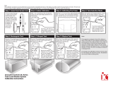
2. Slow Hold Speed
• The Slow Hold Speed function is used to avoid loss of seeding coverage caused by loss of
consistent product flow through the metering system when travelling too slowly.
• If the implement is travelling below this speed (but above the minimum speed) then
metering system is regulated as if the implement were travelling at the Slow Hold Speed.
• NOTE: Slow Hold is an optional function that can be set to operate at a minimum speed
required to give a consistent flow of product through the metering system for a given target
rate (speed-based).
To calibrate speed-based Slow Hold:
1. Exit to the Front Screen and start seeding in AUTO mode at normal speed, then slow down until the
metering drive almost stops.
2. Take note of the ground speed when this happens and use this point for Slow Hold Speed calibration.
3. Navigate back to this menu and highlight Slow Hold Speed.
4. Adjust to set the desired hold speed (km/h).
Operating with Slow Hold active will mean the product is being over applied
and may cause double sowing!
Speed
Control
Rate
Slow Hold
Speed
Minimum
Speed
Rate @
Slow Hold
Speed

March 2020 www.farmscan.com.au AM-7500-5
18
Machine Setup
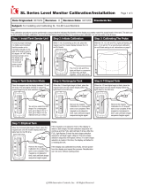
Prime Mode operation explanation
The Prime Mode operation turns on the Seeder metering system before speed is detected from the speed
sensors. This allows product to begin metering before moving off preventing any missed areas due to a
metering lag. The product will be regulated as if the implement was travelling at the Prime Speed. If the
implement exceeds the Prime Speed or the Prime Time then the product will be regulated normally.
1. Enable Prime
a. If Prime Mode is enabled, the metering control will enter Prime Mode instead of Run Mode.
2. Prime Time Mode
a. Set Time: When Prime is enabled and Prime Time set, after X seconds the metering control
will revert to Run Mode.
b. Continuous: The unit will remain in Prime Mode indefinitely. NOTE: This should NOT be
used in standard operation but it is useful for “stand still” testing and demonstration.
3. Prime Time
a. If Prime Mode is entered, after the selected number of seconds metering control will revert
to Run Mode.
4. Prime Speed
a. When in Prime Mode, the metering control is regulated as if the implement was travelling
at the Prime Speed.
b. If the implement exceeds the Prime Speed, metering control will revert to Run Mode.
Speed
Control
Rate
Prime
Speed
Revert
to Run
Mode
Rate @
Prime
Speed

March 2020 www.farmscan.com.au AM-7500-5
19
Machine Setup
AUXILIARY SETUP / DUMP VALVE (1B)
By default, the 7500 will select the output/control configuration depending on the UniPOD purchased.
Auxiliary Setup allows the user to customise which input goes to each sensor.
• Master Clutch
o Clutch #
• Master Bin Level
o Level Input #
• Master Dump (Liquid)
o Dump Valve #
When 1x UniPOD is installed only 3 free AUX when using a VRC-3 and 4 free Aux with VRC-2
Input #
Application
Auxiliary # 1
Select Option
Auxiliary # 2
Select Option
Auxiliary # 3
Select Option
Auxiliary # 4
Select Option
Auxiliary # 5
Select Option
Auxiliary # 6
Select Option
When 2x UniPOD’s is installed
Input #
Application
Auxiliary # 7
Select Option
Auxiliary # 8
Select Option
Auxiliary # 9
Select Option
Auxiliary # 10
Select Option
Auxiliary # 11
Select Option
Auxiliary # 12
Select Option
To change the values:
1. Select the Auxiliary number that you want to change.
2. A selection of available options will be displayed.
3. Select the valve type required.
4. Select the green Tick button to save changes.
NOTES:
• Please note UniPODs & harness’s come in different configurations.
• If you are unsure of Auxiliary setup, please contact the Farmscan service department or your OEM
partner.
/