Page is loading ...

Pro 1500 / Pro 2000
Dust Collector
Owner’s Manual
9_11
Oneida Air Systems, Inc. 1001 West Fayette St., Syracuse, NY 13204
Phone 1.800.732.4065 315.476.5151 Fax 315.476.5044 www.oneida-air.com
Shown with
optional Stand.
Models may vary slightly
in appearance.
5 Year
Warranty
Filter Flame Guard
Arrestor - U.S.
Pat. # 8,496,719

Pro 1500 / 2000 © O.A.S. 2010
1
Thank You for Choosing an Oneida Air Systems Product!
OAS manufactures and sells dust collection equipment only. Our qualied technicians and sales staff are available
7:30am - 6:00pm EST Mon. - Thurs. and 7:30am - 5:00pm EST Fri. to answer any questions concerning OAS products
and dust collection. Call for ductwork design and ductwork quotes, including system pricing and shipping cost.
Read the entire Owner’s Manual before installing or operating system!
Proudly Made
in the USA
I.
II.
III.
IV.
V.
VI.
VII.
VIII.
IX.
X.
XI.
XII.
XIII.
XIV.
XV.
XVI.
XVII.
XVIII.
XIX.
XX.
2
3
4
5
6
7
8
9
10
11
11
12
13
14
15
16
17
18
19
20
System Start-Up Information
Congurations
General Specications & Fan Performance Curve
Dimensions
General Assembly
General Assembly Instructions
General Assembly Instructions
Bracket Assembly
Stand Assembly
Drum Assembly
Filter Assembly
Filter Maintenance
Directions for Cleaning Filter
Filter Efciency Gauge Mounting Instructions
Fan Motor Maintenance
Remote Wiring Diagram
Accessories
Troubleshooting
Fire Hazards - Read Before Installing System
Terms & Conditions
Table of Contents
Page

I. System Start-Up Information
The Dust Collector & Fan / Blower is heavy! Handling and installation should always be performed
by experienced and trained personnel who have experience with rotary equipment. In addition to
the following instructional manual, care should be taken to ensure compliance with specic safety
requirements mandated by federal, state and local codes.
Pro 1500 / 2000 © O.A.S. 2010
1. Read the installation and maintenance instructions as well as the recommended safety practices in this
manual
3. Motor is pre-wired at the factory. If magnetic starter trips circuit, check the following:
1. Dust drum securely fastened to discharge of cone?
2. Is ductwork installed at cyclone inlet?
2. Install ductwork completely before operating collector:
A.) Seal ductwork with silicone sealant or duct tape.
B.) Have dust bin in place and sealed.
Caution
Warning
Warning
Do not operate Fan / Blower unless Fan Housing is attached to Cyclone body and Dust Drum is in
place. Dust Drum and Cyclone must be in place and sealed or motor will overheat!
If amperage is too high - shut down immediately! See Troubleshooting section.
For Customer Service:
866 - 387 - 8822 or [email protected]

II. Pro Congurations
Wall Bracket
Included Square to Round Inlet
Included Filter Efciency Gauge
Included Magnetic Starter
Included Silencer
Do Not Remove
Pat. Pending
11/313,728
Shown with optional
Stand.
3
Pro 1500 / 2000 © O.A.S. 2010
1. External Cartridge Filter - Silencer Included with Filter
Caution:
Cartridge Filter Media
Flame Guard Arrestor - Pat. #8,496,719
If exhaust air is vented outside you must provide make up / return air.
Flue gases (carbon monoxide) can be drawn into the shop from furnaces,
water heaters or other appliances.
GE Certied (H-12) HEPA media. MERV 16+ rated.

Pro 1500 / 2000 © O.A.S. 2010
4
III. General Specications & Fan Performance Curves
System
Performance
System
Dimensions
Options
Ht. w/ 35 Gal. Drum: (3hp) 94” / (5hp) 97.5” Wall Mount
Footprint w/ Ext. Cart.: 27” x 53”
Inlet Diameter: Full Welded (3hp) 7” or (5hp) 8”
w/ Neutral Vane
Outlet: Rectangle (Square to Round Adapter included)
Weather-Proof Cyclone and Fan Blower
Seam-Welded Cyclone Body
Duct Design Service
Stand for Free Standing Unit
55 Gal. Steel or Fiber Drums
Bag Gripper, Plastic Bag Hold-Down System
Remote Starter - Radio Frequency
Filter Efciency Gauge
Filter Grounding Wire
Flame Guard Arrestor - Pat. #8,496,719
Integral
Fan Blower
Filter Media
Included
Sound Level
Dust Bin
U.S. Made Baldor / 3hp 1 & 3 Ph. - 5hp 1 & 3 Ph.
TEFC Motor / Insulation Class F
Voltage: (3hp) 1 Ph. 230V / 3 Ph. 208-230/460V
(5hp) 1 Ph. 230V / 3 Ph. 208-230/460V
Amperage: (3hp) 1 Ph. 14.5A / 3 Ph. 8.1-7.6/3.8A
(5hp) 1 Ph. 19.5 / 3 Ph. 13.2-12/6A
110 Sq. Ft.
GE Certied (H-12) HEPA media. MERV 16+ rated.
5 Yr. Warranty / Patented Internal Silencer
Magnetic Starter -
With Standard Silencer & Filter: (3hp) 80 - 82 dBA @ 10’
(5hp) 80 - 83 dBA @ 10’
35 Gallon Fiber Drum. Other Sizes & Types Available.
Cast Aluminum Alloy 356-51 / Backward Inclined /
Non-Sparking, Non-Ferrous as Required by NFPA
Fire Code / Dynamic, Two-Plane Balanced to ISO 6.3
Specications. The Same as Aircraft Turbine Rotors.
Industrial
Quality
Motor
w/ On-Off Switch Preset for Add-On Remote with
Amperage Overload Protector (1 Phase)
(3hp) 2548 CFM - Free Fan Rating
(5hp) 2959 CFM - Free Fan Rating
(3hp) 1593 CFM @ 2.3 SP w/ Filter - Actual Working CFM
(5hp) 1973 CFM @ 2.3 SP w/ Filter - Actual Working CFM
XXK150001H
XXK150003H
XXK200001H
XXK200003H
Pro Series (3hp)1500 Dust Collector - 1 Ph.
Pro Series (3hp)1500 Dust Collector - 3 Ph.
Pro Series (5hp) 2000 Dust Collector - 1 Ph.
Pro Series (5hp) 2000 Dust Collector - 3 Ph.
Part # Description
Patented
Internal Silencer
Outlet can be
rotated independent
of the inlet
Shown with Optional
Stand.
*Oneida reserves the right to change or modify specs and system
appearance without notice. Actual system appearance may vary.
Pro 1500 w/o Filter
Pro 2000 w/o Filter
Patent
Pending
Pro Series 1500 & 2000 System Performance Curve - CFM vs. SP*
Actual Working CFM -
Fan Curves - See below.
(3hp)
94”
(5hp)
97 1/2”
Wall
Mount
Dimensions shown w/ 2” ex hose
between drum and cone collars.
Allow 1 - 2” from
ceiling for motor
venting.

Pro 1500 / 2000 © O.A.S. 2010
5
IV. Dimensions
For Minimum Mounting Heights w/ 39” Filter
*Dimensions subject to slight variation in manufacturing.
94.00
7” / 8”
94.00 /
97.5
6.00
36”

Pro 1500 / 2000 © O.A.S. 2010
6
V. General Assembly
- (Pro 1500) XXK150001 1 Phase / XXK150003 3 Phase
- (Pro 2000) XXK200001 1 Phase / XXK200003 3 Phase
5c
5b. J-Hooks (8) - AFJ051602 / AFT000001
5d. Dust Pan - FPZ000018
6
7
18” x 36” HEPA Media Filter w/ Pat. Pend. Flame Guard Arrestor
5d
5a. Plenum - FPX000001
3. Cyclone Barrel - SXI002109 / SCI002309
4. Cyclone Cone - SCX012109 / SCX002309
5c. Filter Plate - (13”) FPX010013 / (18”) FPX010018
16
Filter Grounding
Wire - FGA000000
(8) Spring Clips
Drum Grounding
Wire - FGA000001
17
(8) Spring Clips
Bolts

7
Pro 1500 / 2000 © O.A.S. 2010
VI. Assembly Instructions
Clips - AFT051618
Motor Plate
Gasket
Material
Gasket material goes
outside of clip holes
on top and bottom of
fan housing.
Gasket
Material
Collector
Barrel
Fan
Housing
Washer
Washer
Bolt
Bolt
Clip
Instructions for assembly of the Fan Blower Housing and Barrel of the Oneida Models.
1. Push clips onto inside circle on Fan Housing, making sure clip is pushed all of the way on, that the bolt
holes are in alignment with the clip holes and that the small barrel on the clip is on the INSIDE of the Fan
Housing as shown in diagram.
2. Stick the gasket material around the Fan Housing as shown in the diagrams, outside of the bolt circle.
Making sure of a complete seal. Dust collection systems cannot operate effectively without being tightly
sealed with no air leaks.
3. Put bolt through washer. then into appropriate bolt holes in Fan Housing and Barrel. Tighten bolts so
they all are snug, then go back and nish tightening the bolts in a star pattern.
Proportions and sizes of parts may be
exaggerated for purposes of explanation.
It is CRITICAL that this part
of the clip is put on the inside
of the Fan Blower Housing as
shown here. Otherwise you
will not get the seal needed for
complete dust collection!

Pro 1500 / 2000 © O.A.S. 2010
8
VII. General Assembly Instructions
Do NOT use hook on motor to lift unit.
There are essentially three ways to assemble your collector and to at-
tach it to the stand. The way that is right for you should be determined
by expertise and manpower available. When the units are all assem-
bled they are very heavy and top weighted. All of this should be taken
into account before deciding on the method best suited for you.
With all assemblies, make sure rectangular air
outlet is oriented on Fan/Blower housing as
you are looking down as in Fig. 1A or facing it
as shown in diagrams. This is very important.
Then you can rotate the housing to whatever bolt
position is best for your shop.
Before you start, make sure you have cut and placed the provided
gasket material on top and bottom of the Fan / Blower housing and the
Cone as shown in the diagrams. Then determine which direction you
want your lter to hang and which direction your ductwork will enter
the collector.
Bolt Fan / Blower housing to Cyclone barrel, Then bolt Motor and
Plate to Fan/Blower housing. Carefully lay unit on its side and then
bolt cone to barrel. Lift entire unit up onto stand. Unit is extremely
heavy and top weighted, be advised!
Bolt Fan / Blower housing to Cyclone barrel, Then bolt Motor and
Plate to Fan/Blower housing. Put Cone up on stand and orient holes.
Lift assembled unit onto cone making sure proper holes are lined up.
Bolt unit to stand, then nish bolting barrel to cone.
Bolt Fan / Blower housing to Cyclone barrel, Put Cone up on stand
and orient holes. Lift assembled unit onto cone making sure proper
holes are lined up. Bolt unit to stand, then nish bolting barrel to
cone. Lift Motor & Plate onto Fan/Blower housing and bolt together in
proper direction.
Method #1 -
Method #2 -
Method #3 -
Note: For preseparation there must be an air tight seal between cyclone and dust container. Dust bin must
be located vertically under cyclone. Material drops down by gravity.
Use the previous page for directions on attaching
the Fan Motor Housing to the Motor Plate and Bar-
rel.

VIII. Bracket Assembly
1. You must determine the direction the fan outlet will point to proceed
with this mounting assembly. The collector will seem quieter if the outlet
is aimed away from the area people tend to work. Slots in the brackets
are .406” x 1.00”.
Note: Bolts included to mount bracket to collector. Hardware NOT
included to mount to wall.
2. Hold bracket against wall with top of plate at 56”. Mark where mount-
ing holes fall. Mount wall bracket. For wall mounting, the bolt centers on
the brackets are at 16” & 24” to accomodate most wall stud spacing. See
Fig. 1 & 2. Use a level to ensure straightness.
3. Attach bracket to wall with lag screws, concrete anchors, or other
suitable hardware. See Fig. 2 & 3. Note: When installing the brackets on
a concrete wall, mount 2 x 4’s between wall and brackets to stabilize and
dampen vibration.
4. Position Angle Ring around top of cone over bracket. Line up one hole
in ring with hole in each bracket at desired rotation of outlet. If rotation
you desire does not correspond to an existing hole in Angle Ring, drill
new ones. Use three 3/8” bolts (included) with washers & lock washers
to secure the fan. See Fig. 4.
5. Attach tightly with bolts.
Put at 69” if you are
using a 55 gal. drum.
Pro 1500 / 2000 © O.A.S. 2010
9
24”*
26 1/4”
15 7/8”
11 1/4”
16 1/4”
* only 5hp Bracket has 24” holes

Pro 1500 / 2000 © O.A.S. 2010
10
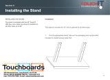
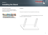
IX. Stand Assembly
Stand Kit Contents
Stand Leg Set 35 Gal. (4) - SXX000035
Stand Leg Set 55 Gal. (4) - SXX000055
Mid-Gusset (4) - RFG010001
Top Gusset (4) - RFG010000
Rubber Leg Cap (4) - RCR012500
Hardware Kit (1) - AHX000100
1. Attach Top Gusset to the top of leg as shown in photo with (2)
1/4”-20 x 2” bolts. Then secure with 1/4“ Flat Washer and 1/4”- 20
Nylock Nut. Attach Mid-Gusset to middle of leg as shown with (2)
1/4”-20 x 3/4” bolts and secure with 1/4” Flat Washer and 1/4”- 20
Nylock Nut. Put Rubber Leg Cap on bottom of leg. Repeat on other
three legs.
2. Attach Stand Braces to the inside of Mid-Gussets with (2) 1/4”- 20
x 3/4” bolts and secure with 1/4” Flat Washer and 1/4” - 20 Nylock
Nut. Adjust the legs for the 21” or 23” cone by positioning the bolts in
the appropriate position in the slotted brace hole. After assembly,
make sure your Dust drum slides between the legs for easy empty-
ing.
3. You may want to put the stand on it’s side when you attach the
collector cone and barrel. Always have appropriate help when
lifting or moving the stand and collector. The unit is heavy!
4. Bottom of Cone and Barrel rim go on top of stand gussets. Use the
included cyclone hardware to attach to stand. Use (2) 5/16” x 1”
bolts, (2) 5/16” flat washers and (2) 5/16” whiz nuts on each gusset.
35 & 55 Gal. Stand - STG000035 / STG000055
Stand
Brace
Top Gusset
Mid - Gusset
Rubber Leg Cap
56” / 68”
27.5”
27.5”
Stand Brace (4) - RFG010002
2

Pro 1500 / 2000 © O.A.S. 2010
11
Filter
Mounting
Plate
Gasket
Plenum
Support
Hanger
J Hook
Gasket
Outlet
J Hook
XI. Filter Assembly
X. Drum Assembly
External 36” Filter Assembly
*Silencer Included
5. Attach lter cartridge with provided J hooks making sure
the gasket is sealed tightly and internal silencer is in lter.
7. Attach the lter dust bin to the bottom of the lter with
the J hooks making sure that the seal is tight.
1. Attach gasket to collector outlet making sure there are
no gaps where gasket ends meet.
Distance between the drum lid and cone can
vary. Some systems have little space there to
minimize overall system height.
In some cases, the exible hose will have to be
cut down (especially with stands).
OAS ships 1’ of hose as standard but this is not
necessarily the needed length once the system
is installed.
Tools Needed: Razor Knife / Diagonal
Cutters
Measure length between drum lid and collar of cone.
Measure hose while it is extended (don’t overly compress the hose). This allows the lid to move up when
installed. Cut the hose with razor knife and then cut the wire with diagonal cutters. Don’t cut too short! If
in doubt, cut a little long. Trim if necessary.
2. Attach Plenum to outlet using the included 7 bolts and
hardware making sure the support hanger on the Plenum
is at the bottom.
3. Attach gasket around cut out in lter plate as shown
in diagram, making sure there are no gaps where ends
meet.
4. Attach lter plate to Plenum using the 9 included Carriage
bolts, washers and nuts, putting them up through the plate
and Plenum from underneath making sure the shaped bolt
shaft is snug in the diamond hole in plate.
6. If lter requires additional support, use the plate at the
top of the lter to support the lter assembly or support
hanger on Plenum.
Note: If lter cartridge is located away from the cyclone
and motor, additional square to round connectors and
pipe can be purchased.
Filter Plate
4 hole side is near dust
collector.
Drum Grounding Wire
To attach the Drum
Grounding Wire, start a
small hole in bottom of
cone above ex hose
and in the top of the
dust drum, then attach
the wire with the 3/8”
included self-tapping
screws.
Gasket

Pro 1500 / 2000 © O.A.S. 2010
12
XII. Filter Maintenance
External Filter Cartridge Cleaning Intervals
When unit is turned off, use compressed air to blow dust off from
exterior of lter. Hold nozzle at least 6” away from lter pleats*.
Do not remove bottom dust pan before or during the blow-off
process! Let dust settle into dust pan. Unclip and dump out dust.
Filter removal is not required.
*WARNING: A close, direct blast with the compressed air nozzle
too close to lter, may damage lter media. Always wear safety
glasses while blowing off lter.
Fan / Blower & Cyclone Outside Placement
Fan / Blower has a TEFC - Totally Enclosed Fan Cooled Motor.
Note: Use steel drum when placed outside.
Before Operation:
Mount system and connect cyclone and dust bin. Make sure dust bin is in place and ductwork is connected
to inlet before turning on the dust collector.
Electrical Wiring:
Make sure power source matches wire voltage congurations on motor.
Prior to connecting to the power line, check motor plate for proper voltage. Motor is pre-wired for counter-
clockwise rotation. Fan wheel must rotate counter-clockwise if looking down on fan housing.
Use 12 gauge cord for the fan / blowers.
Lubrication:
See pg. 15 for schedule and specications.
Caution: Rotating Fan Blades! Keep objects clear of outlet.
Do not operate Fan / Blower unless Cyclone and Dust Bin are in place! Motor will overheat!
Caution: Fine dust collected in lter is hazardous to
your health! Do not breathe!
Shown with
optional Stand.
Attach the ring terminal on the green
ground wire from the motor to a bolt on the
lter plate, under the nut. Then attach the
alligator clip to the lter cage as shown in
Fig. 1.
Figure 1
Filter Grounding Wire
Filter
Grounding
Wire

Pro 1500 / 2000 © O.A.S. 2010
13
XIII. Directions for Cleaning the Filter
All steps should be done with a dust mask and eye protection. Proper lter clean-
ing should not be neglected. A dirty lter can affect dust collector operation and
lter life.
1. Compressed air from outside.
Blast air along pleats of the lter at about a 20 degree angle.
Blast air out and away from you or anyone in the general area.
Keep air nozzle at least 6” from lter. Closer blasts may dam-
age material. This operation should be done with lter on the
unit. Dust is trapped inside lter so it will not make a mess.
Filter must be cleaned regularly or lter damage may
result. If gauge reaches 3, it is time to clean your l-
ter. Never allow gauge to reach 5. You could destroy
your lter. See page 14.
6”
XII. Wiring Instructions for Magnetic Starter
Follow wiring diagram on motor.
Always use a licensed, professional electrician.
Note: This Dust Collector is pre-
wired at the factory and need only
be plugged into a NEMA 6-20R
dedicated electrical receptacle.
#hp single phase only.
2. Empty Dust Bin.
Wait a few minutes for internal dust to settle then unscrew
thumb nuts from J-Hooks and remove dust bin. Empty dust
carefully. Replace dust bin. Do not over tighten thumb nuts.
Filter
J-Hook
Dust Bin
Thumb Nut

Pro 1500 / 2000 © O.A.S. 2010
14
XIV. Filter Efciency Gauge Mounting Instructions
Mounting Instructions
Gauge Reading Instructions
1. Select a location free from excessive
vibration and where ambient temperature
is between 20 F to 120 F (-6.7 C to 49 C).
You can mount gauge up to 8’ away from
static pressure tube. Gauge bracket can be
mounted to stand gusset for easy reading.
2. Mount brass static tube in plenum with tip
pointed into air stream. Use included mount-
ing bracket and sheet metal screws if interior of
plenum is not accessible. Refer to the drawings for
location of brass static pressure tube. Use 13/32”
drill bit for hole.
3. Put gauge through supplied mounting plate with
pre-cut 2 5/8” hole. Put the two bolts from gauge
box through front of gauge. Put metal brace from
gauge box against plate back with gauge bolts
through brace to hold gauge tight against plate. Put
supplied nuts from gauge box on bolts and tighten.
4. Mount plate with gauge to appropriate surface.
If mounting to stand, user must drill a hole and
supply hardware attachment. Connect clear tubing
from brass static pressure tube to port labeled “+”
on the back of the pressure gauge. Make sure
tubing is not crushed or kinked along its entire
length. Cut shorter if necessary.
Before you insert brass static pressure tube, use a marker and
mark top of brass nut where tube will be in the up position so
when you position tube or tighten it, you’ll know where tube is
pointing.
1. Gauge may need to be zeroed. Follow the instructions provided with pressure gauge.
2. Take the initial reading with cleaned lter(s) and the typical number of blast gates
open in normal operation.
3. Always read the gauge with the same number of gates open. The more gates open,
the higher the pressure reading on the gauge.
4. When the gauge rises to 3”, it’s time to clean your lter(s).
After many cleaning cycles, a lter’s pressure will rise after each cleaning.
An older lter does not get as clean as a new lter.
Air Flow to Filter
Metal Plenum
Air Flow to Filter
Silicone
Washer
Up to 8’
away
Plastic Plenum
Air Flow to Filter
Gasket
Plate
Mounting Bracket
Drill 13/32”
hole here.
Either side.
OR

Pro 1500 / 2000 © O.A.S. 2010
15
XV. Fan Motor Maintenance
Wall Mounting Magnetic Starter
Per Baldor specications, their 2 pole motors (3600 RPM) motors are to be relubricated every 5500 hours.
Per Baldor specications, add .30 ounces (8.4 grams)
of Mobil Polyrex grease by weight or .6 cubic inches
(2 teaspoons) of Mobil polyrex grease by volume.
Fastener Captive Fastener
Remove front cover.
Attach Starter cover and tighten Captive Fasteners.
Fasten screws through mounting bracket into
mounting surface. (Screw needs to be smaller than
Captive Fastener.)
Clean the grease tting (or area around grease hole, if equipped with
slotted grease screws). If motor has a purge plug, remove it> Motors
can be re-greased while stopped (at less than 80 degrees C) or run-
ning. Apply grease gun to tting (or grease hole). Too much grease
or injecting grease too quickly can cause premature bearing failure.
Slowly apply the recommended amount of grease, taking 1 minute or
so to apply. Operate motor for 20 minutes, reinstall purge plug if previ-
ously removed. Caution: keep grease clean. Mixing dissimilar grease is
not recommended.
Procedure

Pro 1500 / 2000 © O.A.S. 2010
16
XVI. Remote Wiring Diagram
Retrot (Wiring) of Wireless Remote into 220V Control Circuit of Square D / Telemecanique Mag Starters
Retrot (Wiring) of Wireless Remote into 220V OAS Import Magnetic Starters: AMI020000 / AMI030000
Square D
Telemecanique
Mag Starters
AMK Series
Plug into 9 pin female Molex
on back panel of starter base.
Start / Stop
Push Button
Assembly on
Starter (Molex)
Female Molex
at bottom of
starter.
3 Wire
Adapter
Molex
AMA000000
3
Start
Stop
AMR220000
YEL
YEL
YEL
YEL
Wire
Nuts
YEL
YEL
BRN
BRN
BRN
BRN
BRN
BRN
YEL
YEL
Amp
Adjustment
Dial
YEL
YEL
RED
BRN
BRN
BRN
BRN
Contactor
Overload
Amp
Adjustment
Dial
‘2’
‘3’
‘1A’
BRN
RED
RED
RED
RED
RED
RED
2
4
1
RED
RED
RED
RED
Overload
Contactor
Remove this
factory installed
red wire!
Remote is mounted
inside starter top cover
by using double-sided
tape (Supplied).

Pro 1500 / 2000 © O.A.S. 2010
17
Bolt Together Stand
STG000035 - 35 Gal. Stand
STG000055 - 55 Gal. Stand
Replacement Filter
XVII. Accessories
FCS183600HF
18”x 36” / 110 Sq. Ft. Spun-Bonded. Filters 99.9% of test
material from 0.2 - 2 microns.
18”x 36” / 110 Sq. Ft. GE Certied (H-12) HEPA Mdia /
MERV 16+ rated
w/ Pat. Pend. Flame Guard Arrestor
Dust Containers
35 Gal. Fiber
55 Gal. Fiber
55 Gal. Steel
Holds plastic bag in drum for easy removal and disposal.
Drum Liner - Plastic Bag Hold-Down
ABX000035 / ABX000055
Dust Sentry
™
AXB999110
Patent
Pending
The Oneida Dust Sentry™ with adjustable IST (Infrared Sensing Technology),
ashes a strobe light to alert you when the dust in your container reaches your
preset level, telling you when it’s time to empty the container.

Pro 1500 / 2000 © O.A.S. 2010
18
XVIII. Troubleshooting
Motor Overheating
Poor Dust Pick-Up at Woodworking Machines
Filter Clogging
Excessive Vibration
The motor’s internal circuit breaker will trip if the motor is overheating.
System should be completely bolted and sealed together.
Ductwork should be completely installed and sealed with sealant.
Air leaks between the collector and dust bin.
Motor not properly wired. Check wire connections.
- The lid of the dust bin and the cyclone must be in place and sealed when operating the dust collector.
- Make sure ex hose is not torn and the hose clamps are tight.
- Check drum lid; cover should have a foam seal and be well seated.
- Check for holes or leaks in the dust bin barrel.
Motor amperage too high - Shut system down.
Caused By:
Caused By:
Caused By:
Caused By:
- Check motor rotation - See wire diagram
Check breaker box. Make sure incoming power supply matches motor specications.
Improper motor rotation - Running backwards will reducr suction by 30%.
Check length of duct runs and duct diameters compared to ductwork design guideline.
Make sure all ductwork is sealed. Large air losses will occur even through small cracks in the ductwork.
Use silicone, duct tape or duct mastic compound as a sealant.
Check for air leaks between collector and dust bin.
Close all unused blast gates at your woodworking machines.
Examine hood design for weaknesses according to the ductwork guide.
Check for a restricted pipe, too small a hood port or too small a branch line. See branch line diameter chart
in ductwork guide.
Be sure that your lter is clean. See lter cleaning directions.
Air leakage between cyclone and dust bin. Cyclone and dust bin must be air tight. Even small leaks can will cause
poor pre-separation in the cyclone.
Large chips clogging the lter:
- Check for a leak in the dust bin, ex coupling or lid. Check for split or torn ex coupling. (See also: Motor Over-
heating Section above.)
- Make sure dust bin has not over lled. Dust bin should be emptied before dust reaches top of container.
- Interruption of air ow, such as vacuuming chips with a ex hose connection, will increase lter maintenance.
- Minimum 4” diameter pick up at tool location. Less than 4” will restrict air ow into collector and will increase lter
maintenance, If there is not enough air entry in system, open more blast gates.
- Make sure clamp around cyclone is tight and sealed with silicone.
Loose mounting bolts.
Excessive system pressure or restriction of air due to closed blast gates.
Accumulation of foreign material on the fan wheel.
Inadequate support structure.
Note: If you continue
to experience difculty
with your collector, call
Oneida Air Systems at
1.800.732.4065 for assis-
tance.

Pro 1500 / 2000 © O.A.S. 2010
19
XIX. Fire Hazards
- Read Before Installing and Operating
Oneida Collectors are designed for WOOD DUST only!!
Wood shaping and cutting processes generate wood chips, shavings, and dust. These materials are considered combustible. Air
borne wood dust below 420 microns in size (.017 of an inch) in certain concentration ranges when ignited can deagrate (burn quickly).
An ignition source such as a spark or ember can ignite a dust mixture resulting in an expanding ame front which can cause an explo-
sion if tightly contained. A disturbance that raises a cloud of accumulated ne dust can raise additional dust clouds, which can cause a
series of explosions that can level an entire building. Until this type of re has been witnessed, it is difcult to believe the devastation.
This type of re is rare but worth safeguarding against.
The best way to avoid a wood shop re is to keep the shop clean. A shop ankle deep in dust with layers of ne dust everywhere is an
accident waiting to happen. A good dust collection system reduces overall re hazards but also adds new concerns. A re hazard is still
present. Combustible material is now in the dust collector and storage container.
The following points are worth heeding:
It is the buyer’s responsibility to follow all applicable federal, state, local, OSHA, NFPA, or authorities having jurisdiction codes and
regulations when installing and operating this dust collector.
Fire marshals may want the unit located outside of the building. If the collector is located inside the facility, controls such as spark
detection, suppression, or explosion venting may be required.
Most local jurisdictions consult or adopt NFPA (National Fire Protection Agency) codes. However, other codes may apply. Local
codes may vary from jurisdiction to jurisdiction.
NFPA 664 Code book, “Standard for the Prevention of Fires and Explosions in Wood Processing and Woodworking Facilities”, ap-
plies to woodworking operations that occupy areas of more than 5,000 sq. ft. or to areas where dust producing equipment requires an
aggregate dust collection ow rate of more than 1500 cfm (cubic feet per minute). This exempts some small operators from the NFPA
code 664, but other codes may apply in your jurisdiction. Consult your local Fire Marshall for help. Additional information can be found
in NFPA Code Book 664.
The customer assumes the responsibility for contacting their insurance underwriter with regard to specic application requirements of
explosion venting or if additional re protection and safety equipment may be required.
Do not use this product to collect other types of dust or ammable vapors.
Fire or explosion may occur!
- Never collect sparks from a bench grinder into a wood dust collector.
- Never introduce sparks or sources of ignition into the dust collector.
- Personnel should keep at least 20 feet away from unit.
- Check dust bin frequently and before leaving the shop for smoldering material.
Keep portable Fire Extinguishers handy.
- The ABC type (dry chemical) is generally a good choice for small wood shops. Additional information on portable extinguishers
can be found in NFPA 10 (Standards for Portable Fire Extinguishers).
- Be especially careful with sanding units. They can produce concentrations of dust in the combustible range. Make certain enough
air volume is at the suction point to capture all the particulate generated.
- This high air volume will dilute the mixture below the lower limit of ammability. Be careful not to generate sparks into the sanding
dust.
- Empty dust bin and clean lter often, especially when sanding.
- Don’t overload woodworking equipment, especially sanders. Excessive frictional heat can spontaneously ignite dust.
Sparks can be generated in several ways:
- High-speed sanders and abrasive planers may strike foreign material.
- Saws and edgers may strike foreign material and create a red hot metal fragment.
- Knots in hardwood can create frictional sparks.
- Tramp metal when drawn into the collector can spark against ductwork.
- Check wood stock for old nails and screws which can create red hot metal fragments.
- Avoid using excessively large wood waste storage bins.
- Always check storage bins for smoldering material before leaving for the day.
- Electrically ground all equipment and ducting. Static sparks can ignite wood dust. (Avoid using PVC drainpipe).
- Don’t allow accumulation of layers of ne dust on horizontal surfaces. (Especially overhead lights, electrical boxes, and fuse
panels which can ignite dust).
/