Page is loading ...

10 HP NYB Pulley/Belt Drive
Cyclonic
Dust Collectors
Oneida Air Systems, Inc. 1001 West Fayette St., Syracuse, N.Y. 13204
Phone 1-800-732-4065 315-476-5151 Fax 315-476-5044 www.oneida-air.com
Owners Manual

Thank You for Choosing an Oneida Air Systems Product!
OAS manufactures and sells dust collection equipment only. Our qualified technicians and
sales staff are available 7:30am - 6:00pm EST Mon. - Thur. and 7:30am - 5:00pm EST Fri. to
answer any questions concerning OAS products and dust collection. Call for ductwork design
and ductwork quotes, including system pricing and shipping cost.
Read the entire Owners Manual before installing or operating system!
Proudly
Made in
the U.S.A.
Table of Contents
Page
I.
II.
III.
IV.
V.
VI.
VII.
VIII.
IX.
X.
XI.
XII.
XIII.
XIV.
XV.
XVI.
2
3
4
5 - 7
8
9 - 10
11
12
13 - 14
15
16
17
18
19
20
21 - 23
System Start-Up Information
Pulley Drive Configurations
General Specifications & Fan Performance Curves
Dimensions
Configuration Examples
General Assembly Instructions
External Filter Box Assembly
Wire Diagram
Fan / Blower Maintenance
Accessories
Troubleshooting
Fire Hazards - Read Before Installing System
Terms and Conditions
Filter Cleaning Instructions
Optional Filter Efficiency Gauge Mounting Instructions
Supplemental Instructions for Magnetic Motor Starters
1
O.A.S. 2007
c
10 HP Pulley Drive Owners Manual

O.A.S. 2007
c
10 HP Pulley Drive Owners Manual
I. System Start-Up Information
1. Read the installation and maintenance instructions as well as the recommended
safety practices in this manual.
2. Install Ductwork completely:
A.) Seal ductwork with silicone sealant or duct tape.
B.) Have Dust Bin in place and sealed.
3. Have licensed electrician wire Fan / Blower according to wire diagram in this
owners manual.
4. Have licensed electrician check current draw on motor with all gates open. Current
draw should not exceed maximum motor amperage. (OAS is not responsible for
destroyed motors caused by improper wiring or improper installation.)
Caution
The Dust Collector & Fan/Blower are heavy. Handling and
installation should always be performed by experienced and
trained personnel who have experience with rotary equipment.
In addition to the following instructional manual, care should
be taken to ensure compliance with specific safety
requirements mandated by federal, state and local codes.
Warning
Do not operate Fan / Blower without connecting dustbin.
Never operate Fan/Blower without belt and shaft guard in
place. Keep clear of exhaust. Keep hands and objects clear
of inlet and outlet.
Warning
Check amperage draw during operation with all blast gates
open. Make certain amperage is not outside operating limit
indicated on motor plate! If amperage is too high - shut down
immediately! (See Troubleshooting section.)
2

II. 10hp Pulley Drive Configurations
1. No Filter - Vent Outside -
Caution:
If exhaust air is vented outside you must provide make up /
return air.
Flue gases (carbon monoxide) can be drawn into the shop from
furnaces, water heaters or other appliances.
1. No
Filter
2. External
Cartridge
Filters
3. External
Tube
Filters
O.A.S. 2007
c
10HP Pulley Drive Owners Manual
5 gal. dust buckets not included.
3
10hp has 3 cartridges
10hp has
10 tubes
2 rows of 5

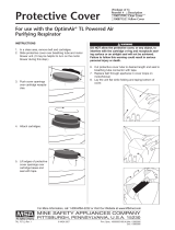
III. General Specifications & Fan Performance Curves
4
10hp Fan Curves
O.A.S. 2007
c
10 HP Industrial Systems Owners Manual
Full welded exterior
Main body, cone and inlet: 16 ga. galv.
Flanged 12 dia. Inlet; Flanged 13 dia. Outlet
80 high
14 rolled steel flange discharge
36 dia. rolled steel flange for mounting
Cyclone C-3500
10hp Fan / Blower
Made in USA NYB 224 DH Arrangement 10
10 horsepower, Pulley drive with weather/shaft guard
TECO - Westinghouse TEFC 60 Hz 10hp Motor
Three Phase: 230/460v 24/12A (Usable on 208v 25.9 A)
Fan Wheel Dia.: 22.625
3300 CFM @ 12 Static Pressure
System Packages Include:
Angle Iron Wall Mount Brackets
Angle Iron Stand
Plenum Box - 10 or 14 hole ring thimble plenum box to hold Tube Filters.
Silencer - For fan / blower outlet to 13 I.D., will reduce noise level.
Magnetic Motor Starters
Rotary Air-Loc
Optional Items:
This fan has moving parts that can cause
serious injury. Read the installation and
maintenance instructions and the AMCA Safety
Practices manual before starting maintenance
or operating.
1. Keep body, hands and objects away from
the inlet, outlet and other moving parts of the
fan such as belts, pulleys and shafts.
During Operation
2. Do not operate at excessive speeds or
temperatures.
Before starting maintenance work:
Lock power supply in off position and
immobilize fan wheel.
WARNING!
Exterior Cartridge Filters
10hp - 3 Cartridges - 390 Sq. Ft.
Spun-Bonded Polyester BIA ZH1/487 Test - Rated C
Captures 99.99% of test material over 20 microns
Captures 99.9% of test material between 0.2 - 2.0
microns @ 11 fpm face velocity
Filter Media
Exterior Tube Filters
10hp - 10 Tube Filters
Needle Felted Media BIA ZH1/487 Test - Rated G
Captures 99.99% of test material over 20 microns
Captures 99.5% of test material between 0.2 - 2.0
microns @ 11 fpm face velocity
55 Gal. Steel Drum
Other large dust bins available
Dust Bins
Static pressure and volume together determine
a fans performance. Several factors, such as
layout of ductwork and diameter of openings,
can affect a fans performance.
Performance -
Horsepower -
5.0
2.5
0.0
Fan Static Pressure (In. Wg.)
10hp Performance Curve
0 1000 2000 3000 4000 5000 6000 7000 8000
7.5
10.0
12.5
9000
0
2.5
5
7.5
10
12
15
17
20
22
Fan Input Power (bhp)
Volume Flow Rate (CFM)

IV. Dimensions
5
O.A.S. 2007
c
10 HP Pulley Drive Owners Manual
Top View Dimensions - Largest Configuration
1 1/2 Flange w/ Bolt Holes
34
10hp - 229
14
10hp - 83
30
42
17
80
Approx.
18
36
1439
36
8
39
32.5
55 Gal.
42
10
12
8
10hp - 10 tube - 83
5 Gal. Dust Buckets Not Included.
They can be bought separately.
- External Tube Filters
32.534
29 1/8
12

IV. Dimensions
6
O.A.S. 2007
c
10 HP Pulley Drive Owners Manual
- External Cartridge Filters
17
80
Approx.
18
36
10
14
1439
10hp - 3 filters -Single Row - 66
36
29 1/8
8
39
62
12
55 Gal.
60
Top View Dimensions - Largest Configuration
34
10hp - 212
14
10hp - 22
1 1/2 Flange w/ Bolt Holes
42
10hp - 3 filters -Single Row - 66
34
Silencer easily drops
into Filter. Hold filter
up to Flange Plate
and clamp.

7
O.A.S. 2007
c
10HP Pulley Drive Owners Manual
C-3500 Cyclone Stand -
Anchor Feet Securely
to Floor to Prevent
Tipping
(4) 3/8-16 x 1 bolts for Cyclone mount
(20) 3/8-16 x 1 bolts for Cross Brace mount
(28) 3/8-16 x 1 bolts for Triangle Brackets
(48) 3/8 flat Washers
(48) 3/8 serrated Nuts
Unit should be shipped with:
w/ 55 Gal. Drum - Part # STZ350055
Choose Mount
Holes to Orient
Inlet in Desired
Location
Inlet
Outlet

V. Configuration Examples
Sleeve Kit - Sleeve-Kit 14 for C-2500
cyclone requires 16 - 18 for a single
drum and 24 for 2x drums. Additional
feet of flex can be purchased to make
the sleeve kit longer if needed.
Drum - Standard 55 gal. steel drums
are usually 35 - 36 high Oneida Air
sells 55 gal. and 35 gal. fiber and steel
barrels with metal lids and snap on
rings.
55 gal. fiber - 35.5 high 22 dia.
35 gal. fiber - 23 high 22 dia.
55 gal. steel - 35.5 high 22 dia.
Rotary Air Locks - Provide an
alternative to an air tight dust bin for
larger volume capacity and less
maintenance. The airlock maintains an
air tight seal which allows material to
drop out into an open container.
A 10 Airlock will drop 1.85 cu. ft. / rev.
of material.
Plenum inside
Flex
Hose
Metal
Drum
Rotary
Air
Lock
O.A.S. 2007
c
10 HP Pulley Drive Owners Manual
Cyclone wall
mounted with
angle iron
brackets
Cyclone -
Fan/Blower outside
Hoppers - see Accessories page
Dust Box - Can be any height. For
efficient pre-separation there must be
an air tight seal between cyclone and
dust bin.
Air Tight Dust Bins can be used as support for cyclone as well as provide large
capacity dust storage.
External
Cartridge
Filter
6, 8,
or 10
Tube
Filters
5 Gal.
Buckets
Fan / Blower
Stand
Splitter
Kit
(2) 55 Gal.
Drums
Cyclone Fan/Blower and filters can
be placed in different locations.
8

VI. General Assembly Instructions
9
O.A.S. 2007
c
10 HP Pulley Drive Owners Manual
1. Determine mounting height for the cyclone.
- Height depends on size of Dust Bin and length
of Flex Hose to Dust Bin connection.
2. Mount Angle Iron Brackets to wall using included
hardware.
3. Mount Cyclone Barrel to Wall Brackets.
- Determine inlet orientation. Fasten Cyclone to
Brackets with one bolt on each side. Drill new
hole in ring if needed for your orientation.
6. Connect Cyclone Cone to Barrel using included
Clamp Ring.
- Seal around Clamp Ring with silicone.
7. Connect 14 to 10 Reducer to bottom of Cone.
8. Connect Sleeve Kit to Cyclone Cone and Dust Barrel
using included Band Clamps.
For cyclonic preseparation there must be an air
tight seal between cyclone and dust container.
Dust bin must be located vertically under cyclone.
Material drops down by gravity.
Inlet
Cyclone
Barrel
Angle Iron
Wall Brackets
Clamp
Ring
Cyclone
Cone
14 to 10
Reducer
Sleeve
Kit
55 Gal.
Steel
Drum
- Seal around Reducer with silicone.
Ideas for make your own Dust Bins:
- 55 gal. drum, metal or rigid plastic garbage can,
air-tight plywood box.
Note: You can make a lid using plywood lined with some
type of gasket material (Carpet Foam).
(Continued on next page.)
4. Lower V - Tube into Cyclone Barrel
5. Connect Outlet Cyclone Barrel to Inlet Cyclone
Barrel using included Clamp Ring.
V - Tube
Outlet
Cyclone
Barrel
Clamp
Ring

VI. General Assembly Instructions
10
O.A.S. 2007
c
10 HP Pulley Drive Owners Manual
7. Set up Fan/Blower
(Cont.)
All moving parts must have guards to protect personnel.
Safety requirements vary, so the number and type of guards
needed to meet company, local and OSHA standards must
be determined and specified by the user. Never start a fan
without having all safety guards installed. Check regularly
for damaged or missing guards and do not operate any fan
with guards removed. Fans can also become dangerous
because of potential windmilling, even though all electrical
power is disconnected. Always block the rotating assembly
before working on any moving parts.
CAUTION
Fan Outlet -
Connect to
Plenum Box
Fan
Inlet -
Connect
to top of
Cyclone
Fan Outlet - Square to round transition for fan outlet
does not come with installation hardware. Drill holes,
bolt screw, or pop rivet to fan outlet, seal with silicone.
Make sure pulley cover and shaft guard are in place
before operation.
8. If applicable, connect silencer to square-to-round
transition.
9. Connect ductwork from fan inlet to top of Cyclone
Barrel.
10. Set up Plenums according to height requirements
for type.
- Instructions for Cartridge Filters
External Filter Cartridge Cleaning Intervals
When unit is turned off, use compressed air to blow dust off from
exterior of filter. Hold nozzle at least 8 away from filter pleats*. Do
not remove bottom dust pan before or during the blow-off process!
Let dust settle into dust pan. Unclip and dump out dust. Filter
removal is not required. You can also run your fingers around the
filter pleats to knock material down.
Clamp filter cartridges to plenum, then clamp
dust bins to cartridges.
- Instructions for Tube Filters - See next page.
- Instructions for build your own plenum - See next page.
Silencer
Square
to
Round
11. Connect ductwork between Fan/Blower outlet or Silencer and plenum.
Plenum
Cartridge
Filters
Dust Bins
Square
to
Round

5 gallon buckets 12 high (Not supplied with
system). Can be purchased, Part No.
SDS050000 or recycled joint compound buckets
or food storage containers can be used.
VII. External Filter Bag Assembly
Plenum Box
22 gauge galv.
Tube Filters
16oz. Needle Felted Polyester
1 Micron Filtration
Hose Clamps
Part # - ACB120000
Hose Clamps
Part # - ACB120000
Ring Thimble
Part # - FAZ000000
6 long - Part # FTS060000
8 long - Part # FTS080000*
10 long - Part # FTS100000
*Note: Also available with zipper
bottoms for 9 ceilings.
1. Connect the plenum to the fan / blower outlet with
the bolts provided. Band clamp tube filters to the
Ring Thimbles on the bottom of the plenum and to
the tops of the 5 gal. buckets.
(Check mounting height - Match to bag heights)
Build your own plenum
Plenum box can be constructed of plywood or metal.
Oneida Air Systems sells 22 gauge galv. plenum boxes.
The filter medium is a 16 ounce polyester felt which has
been singed inside to help release caked dust.
For the tube style filters, a 12 dia. ring thimble (Part #
FAZ000000) is needed for each filter. The plenum box and
the ring thimbles are suspended above the floor at a height
that will allow for a 5 gallon plastic bucket and tube filter to
fit properly underneath.
A well sealed plywood box will make a good plenum for
air distribution through the tube filters. Use plywood for the
plenums. Cut 12 dia. holes in the bottom of the box (spaced
2 - 3 apart), so that the ring thimbles fit snugly. The rings
should not be able to slide through the holes. Bend Ring
Thimble tabs then apply duct sealant or caulk around the
edge of the ring thimble. Use sheet metal screws to secure.
Be sure to remove any sharp edges from the bucket or
ring thimble that may abrade the filter. Slide the filter over
the thimble past the raised bead. Secure with a band clamp.
Slide the bottom of the filter over a five gallon plastic bucket.
Secure with a band clamp or strong bungee (shock cord).
Be sure filter is not loose or moving around when the system
is on. This could lead to wear on the filter.
With the use of a cyclone pre-separator, the buckets will
not need emptying very often, but do need to be checked
occasionally. Simply lift the bucket, the weight will indicate
how full the bucket has become.
12 12 12
2
2
Air
Inlet
Plenum box height - 12 min. Use 3/8 or thicker plywood.
Seal plenum box with silicone.
OAS Galvanized Plenum Box
Note: Plenum hole configuration varies. The number of
holes matches the number of filters.
O.A.S. 2007
c
10 HP Pulley Drive Owners Manual
11

XII. Fan / Blower Wiring Diagram
Wiring should always be done by a licensed electrician!
10 HP Pulley Drive Owners Manual
O.A.S. 2007
c
Before Operation - Before making electrical power connections, check for proper grounding of motor and
application. All electrical contacts and connections must be properly insulated and enclosed. Coupling, belts,
chains or other mounted devices must be in proper alignment, balance and secure to insure safe motor operation.
Electrical Wiring - Prior to connecting to the power line, check motorplate for proper voltage and rotation
connection. This motor should be installed in compliance with the National Electrical Code and any other applicable
codes. Voltage at motor not to exceed + or - 10% of nameplate voltage. Licensed electrician should make all
electrical connections.
Always use the wire diagram on the motor plate. Sometimes the wire diagrams on the motor will be for different
rotation. Wire for counter-clockwise rotation.
12
Ground: Connect house ground
wire to green chassis screw in
motor wire housing box.
Motor
Wire
Box
Green
Chassis
Screw
***
To reverse rotation interchange any two power line leads.
Electrical Disconnects - Every motor driven fan should have an independent disconnect switch to isolate the
unit from the electrical supply. It should be near the fan and must be capable of being locked by maintenance
personnel while servicing the unit, in accordance with OSHA procedures.
Locate factory applied rotation arrow on blower cabinet to establish
rotation direction. It is not possible to know beforehand, which direction
a 3-phase motor will rotate. Bump start the motor and observe the
direction of rotation of the end of the blower shaft (see hole in NYB
outer cabinet that is aligned with the end of the blower shaft.)
Motor should be
wired per factory
applied rotation
arrow on cabinet.
Sticker located
on backside of
blower.
Follow Motor Plate for wiring diagram.

IX. Fan / Blower - Maintenance
The Fan / Blower has a TEFC - totally enclosed fan cooled motor that can be placed outside.
The fan housing is adjustable by 22 1/2 degree increments - outlet can be oriented by adjusting bolt
hole locations between the scroll and the bracket assembly. Fan blowers come as clockwise up blast
from Oneida Air Systems.
13
Item
Dimensions
(Inches)
Dimensions
(mm)
ABDFGHLMNRSTVW
17 1/5 12 5/8 10 1/8 14 1/2 12 1/4 34 1/8 11 9 1/2 22 6 5/8
18 5/18
8 7/8 8 9 1/2
445 321 257 368 311 867 279 241 559 168 465 225 203 241
A high pressure blower requires a certain amount of resistance which will prevent motor over
amperage.
Make sure power source matches wire voltage configurations.
Check set screw and key in fan wheel, make sure fan wheel is secure, fan blower should not
vibrate.
REMINDER: Check Motor and Fan Lubrication Schedule.
Maintenance of Fan / Blower
1.) Electrical -
Failure to follow instructions and safe electrical procedures could result in serious injury or death.
Disconnect all power and discharge all capacitors before servicing. Install and ground per local and
national codes. Consult qualified personnel with questions or if repairs are required.
Electrical Connections
A) All wiring, fusing, and grounding must comply with National Electrical Codes and local codes.
B) To determine proper rotation and voltage connections, refer to the wire diagram section of this
manual.
C) Use the proper size of line current protection and motor controls as required by the National
Electrical Code and local codes. Recommended use is 125% of full load amps as shown on the
nameplate for motors with 40 degrees Celsius ambient and a service factor over 1.0. Recommended
use is 115% of full load amps as shown on the nameplate for all other motors. Do not use protection
with larger capacities than recommended. Three phase motors must have all three phases protected.
O.A.S. 2007
c
10 HP Pulley Drive Owners Manual
WARNING: Rotating Fan Blades.
Keep Objects Clear of Inlet and Outlet.
DANGER!
Do not open until the power
supply has been locked off and
the shaft has stopped rotating.
Failure to do this can result in
serious injury.

14
O.A.S. 2007
c
10 HP Pulley Drive Owners Manual
Maintenance of Fan / Blower (Cont.)
2.) Cleanliness - Keep both the interior and exterior of the motor free from dirt, water, oil and grease.
3.) Safety - Motors should be installed, protected and fused in accordance with latest issue of
National Electrical Code, NEMA Standard Publication No. MG2 and local codes. Rotating parts such
as pulleys, coupling, external fans, and unusual shaft extensions should be permanently guarded.
Keep hands and clothing away from moving parts. Electrical repairs should be made by trained,
qualified personnel only.
4.) Location - The free flow of air around the motor should not be obstructed. The motor should
never be placed in a room with hazardous processes, or where flammable gases or combustible
material may be present, unless it is specifically designed for this type of service.
5.) V-Belt Drive -
A.) Align sheaves carefully to avoid axial thrust on motor bearing. The drive sheave on the motor
should be positioned toward the motor so it is as close as possible to the bearing.
B.) When adjusting belt tension, make sure the motor is secured by all mounting bolts before
tightening belts.
C.) Adjust belt tension to belt manufacturers recommendations. Excessive tension will shorten
bearing life. Insufficient tension shortens bearing life, can reduce fan performance and may
cause vibration. Belts may slip during start-up, but slipping should stop when fan reaches full
speed.
X
Y
E
D
C
Key E locks moveable
side(s) of sheave after
pulley has been adjusted.
Do not operate
Sheave with flange
projecting beyond
the hub end.
6.) Condensation Drain Plugs - All explosion proof and totally enclosed motors are equipped with
automatic drain plugs, which should be kept free of oil, grease, paint, grit and dirt. The drain system
is designed for normal floor (feet down) mounting. For other mounting positions, modification of the
drain system may be required. Consult the manufacturer.
7.) The factory installed bearings in the motor are double shielded (permanently sealed), pre-
lubricated, ball bearings without grease fittings and dont need relubrication. The bearing part
numbers are as follows: Drive End / 6309ZZ, Opposite Drive End / 6307ZZ. If the bearings ever
need replacing, the motor should be taken to an EASA (Electrical Apparatus Service Association)
certified shop to ensure proper installation.
D.) Sheaves should be in accordance to NEMA Spec. MG-1 or as approved by the manufacturer
for a specific application.
Adjusting:
1.) Loosen setscrews Y and C in moving parts of sheave. Turn pulley so Key E drops down & out of the way.
2.) Adjust sheave pitch diameter for desired speed by opening moving parts 1/2 or full turns from closed position.
Do not open more than six full turns for B belts.
3.) Tighten setscrew Y over key and setscrew C over flat surface machined into sheave center hub.
Torque set screws to the following values: 100 in. lbs. minimum to 130 in. lbs. maximum.
4.) Put on belts after elevating motor mount plate and adjust belt tension to proper value. Do not force belts over
grooves.)
5.) Future adjustments should be made by loosening the belt tension and increasing or decreasing the pitch diameter
of the sheave by half or full turns as required. Readjust belt tension before starting drive.
6.) Be sure that all keys are in place and that all setscrews are torqued properly before starting drive. Check
setscrews and belt tension after 24 hours of service.
7.) Replace shaft and pulley guards covers.
Set screw X locks
sheave to motor shaft.
Replacement Belt Part Numbers
10hp
15hp
B44 Belt
BX44 Belt
BLZ440000
BLZ440001

X. Accessories
O.A.S. 2007
c
10 HP Pulley Drive Owners Manual
Dust Bin Options - (Must Order Custom Cyclone Mounting Stand.)
2. Hoppers -
Large capacity hoppers from .5 cu. yd. to 3 cu. yd.
3/16 reinforcing angle for added support - 3/16 plate body is 100%
continuously MIG welded on inside - 3/8 rear cross brace angle (not 3/16)
- three 3 base channel - All angles are structural not formed.
3. Air Locks -
Rotary air locks provide an
alternative to an air tight dust bin
for larger volume capacity and
less maintenance.
Example - A 10 air lock will drop
1.85 cu. ft. / rev. of material.
1. Multiple Drums -
Custom order the System Mounting Stand for multiple drums or
hoppers. Stand widths will vary depending on dust container.
Magnetic Motor Starters - The 10 and 15hp pulley drive dust collectors
do not come wired or with an on/off switch. Because of the voltage
and amperage requirements of the system, an industrial switch must
be used.
OAS offers Square D Full Voltage Non-Reversing across the Line
Starters, Nema Type 1 Enclosure with Start/Stop in cover, and class
10 overload. Industrial switches can also be purchased through your
local electrician. Due to varying electrical codes, OAS cannot specify
exact wiring requirements. When wiring the collector you should
always hire a licensed electrician.
Bin Level Monitor - Provides level sensing for dry bulk solids. The monitor
operates by using a 1 rpm synchronous motor to rotate a paddle.
When paddle rotation is impeded by material surrounding it, the motor
is de-energized and triggers a SPDT snap switch. The snap switch can
be used in conjunction with a motor starter to turn equipment off or provide
alarm functions.
15
Angle Iron Stands
STZ350055 - Angle Iron Cyclone Stand
STZ990000 -Plenum Stand
4. Cone w/ Clean Out -
Optional cone with clean
out plate for use with
airlocks..

XII. Troubleshooting
Motor Overheating
The motors internal circuit breaker will trip if the motor is overheating.
Air leaks between the collector and dust bin
- The lid of the dust bin and the cyclone must be in place and sealed when operating the dust collector.
- Make sure flex hose is not torn and the hose clamps are tight.
- Check drum lid; cover should have a foam seal and be well seated.
- Check for holes or leaks in the dust bin barrel.
Caused By:
Motor not properly wired. Check wire connections.
- Check motor rotation - See wire diagram
Check breaker box. Make sure power supply is 220V.
Poor Dust Pick-Up at Woodworking Machines
Caused By:
Check length of duct runs and duct diameters compared to ductwork design guideline.
Make sure all ductwork is sealed. Large air losses will occur even through small cracks in the
ductwork. Use silicone, duct tape or duct mastic compound as a sealant.
Check for air leaks between collector and dust bin.
Close all unused blast gates at your woodworking machines.
Examine hood design for weaknesses according to the ductwork guide.
Check for a restricted pipe, too small a hood port or too small a branch line. See branch line
diameter chart in ductwork guide.
Be sure that your filters are clean. See filter cleaning directions.
Filters filling with large chips and excessive dust
Caused By:
Air leakage between cyclone and dust bin. Cyclone and dust bin must be air tight. Even small leaks will cause
poor preseparation in the cyclone.
- Check drum for any leaks.
- Make sure drum lid forms a good air tight seal with the drum.
- Check flex hose connection. Make sure hose clamps are tight. Seal with silicone.
- Make sure dust bin has not over filled. Dust bin should be emptied before the dust reaches
top of the container.
- Make sure clamp around cyclone is tight and sealed with silicone.
- If there is not enough air entering system, open more blast gates.
- Minimum 4 diameter pick up at tool location. Less than 4 will restrict air flow into collector and
will increase filter maintenance.
O.A.S. 2007
c
10 HP Pulley Drive Owners Manual
16
Improper motor rotation - Running backwards will reduce suction by 30%.
Excessive vibration
Caused By:
Loose mounting bolts, set screws, bearings or couplings.
Bent shaft due to mishandling or material impact.
Accumulation of foreign material on the fan wheel.
Excessive system pressure or restriction of airflow due to closed blast gates.
Inadequate support structure.
Note: If you continue
to experience
difficulty with your
collector call Oneida
Air Systems at 1-
800-732-4065 for
assistance.
Unplug unit before servicing or cleaning.

XII. Fire Hazards -
Read Before Installing and Operating
17
O.A.S. 2007
c
10 HP Pulley Drive Owners Manual
Do not use this product to collect other types of dust or flammable vapors.
Fire or explosion may occur!
Never collect sparks from a bench grinder into a wood dust collector.
Never introduce sparks or sources of ignition into the dust collector.
Personnel should keep at least 20 feet away from unit.
Check dust bin frequently and before leaving the shop for smoldering material.
Keep portable Fire Extinguishers handy.
The ABC type (dry chemical) is generally a good choice for small wood shops.
Additional information on portable extinguishers can be found in NFPA 10 (Standard for Portable Fire Extinguishers).
Be especially careful with sanding units. They can produce concentrations of dust in the combustible range. Make
certain enough air volume is at the suction point to capture all the particulate generated.
This high air volume will dilute the mixture below the lower limit of flammability. Be careful not to generate sparks into
the sanding dust.
Empty dust bin and clean filter often, especially when sanding.
Dont overload woodworking equipment, especially sanders. Excessive frictional heat can spontaneously ignite dust.
Sparks can be generated in several ways:
High-speed sanders and abrasive planers may strike foreign material
Saws and edgers may strike foreign material and create a red hot metal fragment.
Knots in hardwood can create frictional sparks.
Tramp metal when drawn into the collector can spark against ductwork.
Check wood stock for old nails and screws which can create red hot metal fragments.
Avoid using excessively large wood waste storage bins.
Always check storage bins for smoldering material before leaving for the day.
Electrically ground all equipment and ducting. Static sparks can ignite wood dust. (Avoid using PVC drainpipe)
Dont allow accumulation of layers of fine dust on horizontal surfaces. (Especially overhead lights, electrical boxes,
and fuse panels which can ignite dust)
Oneida Collectors are designed for WOOD DUST only!!
Wood shaping and cutting processes generate wood chips, shavings, and dust. These materials are considered
combustible. Air borne wood dust below 420 microns in size (.017 of an inch) in certain concentration ranges when
ignited can deflagrate (burn quickly).
An ignition source such as a spark, or ember, can ignite a dust mixture resulting in an expanding flame front, which
can cause an explosion if tightly contained. A disturbance that raises a cloud of accumulated fine dust can raise additional
dust clouds, which can cause a series of explosions that can level an entire building. Until this type of fire has been
witnessed, it is difficult to believe the devastation. This type of fire is rare but worth safeguarding against.
The best way to avoid a wood shop fire is to keep the shop clean. A shop ankle deep in dust with layers of fine dust
everywhere is an accident waiting to happen. A good dust collection system reduces overall fire hazards but also adds
new concerns. A fire hazard is still present. Combustible material is now in the dust collector and storage container.
It is the buyers responsibility to follow all applicable federal, state, local, OSHA, NFPA, or authorities having
jurisdiction codes and regulations when installing and operating this dust collector.
Fire Marshalls may want the unit located outside of the building. If the collector is located inside the facility,
controls such as spark detection, suppression, or explosion venting may be required.
Most local jurisdictions consult or adopt NFPA ( National Fire Protection Agency) codes. However, other codes
may apply. Local codes may vary from jurisdiction to jurisdiction.
NFPA 664 Code book, Standard for the Prevention of Fires and Explosions in Wood Processing and Woodworking
Facilities, applies to woodworking operations that occupy areas of more than 5,000 sq. ft. or to areas where
dust producing equipment requires an aggregate dust collection flow rate of more than 1500 cfm (Cubic Feet
per Minute). This exempts some small operators from the NFPA code 664, but other codes may apply in your
jurisdiction. Consult your local Fire Marshall for help. Additional information can be found in NFPA Code Book
664.
The following points are worth heeding:
The customer assumes the responsibility for contacting their insurance underwriter with regard to specific
application requirements of explosion venting or if additional fire protection and safety equipment may be
required.
Unplug unit before servicing or cleaning.

XIII. Terms and Conditions
Please look over the shipped order very carefully in the presence of the delivery person for damage or
incomplete shipment before signing the delivery receipt. Please note any tears or irregularities in shipping
packaging, however slight, on the shipping delivery receipt. This could be an indication of extensive concealed
damage. The shipping company will not take responsibility if the damage is not noted on the delivery receipt.
In the event of shipping damage, call O.A.S. immediately so we can expedite replacements. Please check in
all parts within 3 days from receiving order. Notify O.A.S. immediately of any missing or incorrect parts. O.A.S.
does not accept any claims for damage or shortage after 3 days from date of delivery.
Checking in Order
Oneida Air Systems warrants products it manufactures for a period of 2 years to the original purchaser from
the date of purchase. Items not manufactured by O.A.S. are limited to their own manufacturers warranties. This
warranty does not apply to defects due directly or indirectly to misuse, negligence, accidents, abuse, repairs,
or alterations or lack of maintenance. This is Oneida Air Systems sole written warranty and any and all warranties
that may be implied by law, including any merchantability or fitness, for any particular purpose, are hereby limited
to the duration of this written warranty. O.A.S. does not warrant or represent that the merchandise complies
with the provisions of any law or acts unless the manufacturer so warrants. In no event shall O.A.S.s liability
under this warranty exceed the purchase price paid for the product and any legal actions brought against Oneida
Air Systems shall be tried in the State of New York, County of Onondaga.
Oneida Air Systems shall in no event be liable for death, injuries to persons or property or for incidental,
contingent, special, or consequential damages arising from the use of our product.
Oneida Air Systems does not warrant or authorize use of wood dust collectors for other purposes. This includes
wood products that are treated, coated, or otherwise altered from their natural state.
Limited Warranty
Products will be shipped to Buyers single destination. Title and risk of loss shall pass to the Buyer upon delivery
to such destination. Buyer pays transportation expenses. Dates of shipment are advisory and O.A.S. will make
reasonable efforts to ship on or before the date states for shipment, however, O.A.S. shall not incur any liability
for failure to ship on that date.
Delivery Risk of Loss
Buyer must inform O.A.S. of any shortage or damage, by so noting in writing, on the freight delivery bill prior
to signing to indicate receipt of shipment. All claims, including claims covered under the limited warranty, are
subject to inspection and investigation by O.A.S.. O.A.S. reserves the right to inspect and investigate all returned
products before Buyers claim is settled. All products returned for a cash refund must be unused and resaleable
and purchased within the last six months. There are no refunds on flex hose, custom made components, or
partial kit items. Kits must be returned in full (all components) for credit. There will be a 25% restocking fee
applied to any returned items.
Returned Goods Policy
O.A.S. 2007
c
10 HP Pulley Drive Owners Manual
18
Note: Motors should be protected from extreme weather to prolong motor life.

The External Filter can be cleaned using the following methods:
Wait a few minutes for internal dust to settle
then unclip and carefully empty dust bin.
XIV. Directions for Cleaning External Filter
Keep nozzle at least 6 from filter and keep your
pressure down. Closer blasts may damage filter
material. Rinse off INSIDE of filter. Let filter dry
completely before reuse or keep a spare filter
on hand.
2. Empty Dust Bin.
All steps should be done with a dust mask and eye protection.
3. Rinse with water. (Optional)
1. Compressed air from outside.
Blast air along pleats of the filter at about a 20
angle. Blast air out and away from you or anyone
in the general area.
Keep air nozzle at least 6 from filter. Closer
blasts may damage filter material.
6
O.A.S. 2007
c
10 HP Pulley Drive Owners Manual
19
Filter must be cleaned regularly or filter
damage may result.
/