Page is loading ...

THANK YOU
We appreciate the trust and condence you have placed in Commercial Electric through the purchase of this wall mount. We strive to
continually create quality products designed to enhance your home. Visit us online to see our full line of products available for your home
improvement needs. Thank you for choosing Commercial Electric!
USE AND CARE GUIDE
FULL MOTION TV WALL MOUNT FOR FLAT PANEL TVS
(FITS VESA 100/200/300/400/500/600)
Questions, problems, missing parts? Before returning to the store,
call Commercial Electric Customer Service
8 a.m. - 7 p.m., EST, Monday - Friday, 9 a.m. - 6 p.m., EST, Saturday
1-877-527-0313
HOMEDEPOT.COM
For additional support, call the manufacturer at 1-800-747-6558.
Item #1002 212 033
Model #XD2470

2
Table of Contents
Safety Information ..................................2
Warranty
.
.
.
.
.
.
.
.
.
.
.
.
.
.
.
.
.
.
.
.
.
.
.
.
.
.
.
.
.
.
.
.
.
.
.
.
.
.
.
.
.
.
2
Pre-Installation .....................................3
Installation ........................................6
Safety Information
Before you begin, carefully read and understand the instructions in
this manual. Please follow the instructions in the order presented in
this manual and observe all warnings and cautions.
WARNING: Failure to provide adequate structural
strength for this component can result in physical
injury and/or damage to equipment. It is the installer’s
responsibility to make sure the structure to which this
component is attached can support four times the combined
weight of all equipment. Reinforce the structure as required
before installing the component.
WARNING: This wall or ceiling mount is intended for
use only with the maximum weights indicated. Use with
products heavier than the maximum weights indicated may
result in collapse of the mount and its accessories causing
possible injury. This mount has been tested to support
100 lbs. (45.5 kgs). Do not exceed this weight.
WARNING: Observe all safety measures at all times
during the installation of this product. Use proper safety
gear and tools during the installation process to prevent
physical injury.
CAUTION: Never allow children to climb on or play with
the product.
CAUTION: NEVER use this TV wall mount for DRYWALL
installation.
CAUTION: Do not sit or stand on the product.
CAUTION: Improper handling can result in cuts and
lacerations.
CAUTION: Improper installation may cause property
damage and/or personal injury, so the installation must be
done by two qualied contractors. The manufacture is not
liable for damage or injury caused by incorrect mounting,
assembly or use.
This mount has been tested to support a television with a
minimum of 26 in. (66 cm) and a maximum 70 in. (178 cm)
diagonal screen and a weight up to 100 lbs. (45.5 kgs).
Warranty
The manufacturer warrants that it will replace or repair this item, free of charge, at the manufacturer’s sole discretion, should it prove
defective in materials or workmanship.
This warranty does not apply to:
□ Normal wear and tear
□ Friction damage
□ Coating defects
□ Defects caused by loosened screws, nuts, or bolts
□ Improperly mounting the bracket to the wall
□ Improperly installing the bracket to the display
□ Failure to properly follow installation instructions
□ Modication or repairs not made or authorized by the manufacturer
□ Loading beyond permitted load
□ Intentional misuse
Contact the Customer Service Team at 1-877-527-0313 or visit www.HomeDepot.com.

3 HOMEDEPOT.COM
Please contact 1-877-527-0313 for further assistance.
Pre-Installation
ENSURING THIS IS THE CORRECT WALL MOUNT FOR YOU
IMPORTANT: Review this section carefully before you proceed with this installation to ensure that this is the correct TV
Wall Mount for you.
This TV Wall Mount is the correct wall mount for you if:
□ Your TV size is equal to or no greater than 600 mm x 400 mm (24 in. x 16 in.).
□ Your TV (including any accessories) weighs less than 100 lbs (45.5 kg).
If your TV is greater than these TV VESA measurements and weighs more than 100 lbs (45.5 kg), then this TV Wall Mount is NOT compatible
with your TV.
24 in. (600 mm) Max.
16 in. (400 mm) Max.
PLANNING INSTALLATION
Compare all parts in the package with the Hardware Included and Package Contents lists in this manual. If any part is missing or damaged,
do not install this wall mount system and call customer service at 1-877-527-0313 or visit www.HomeDepot.com.
This wall mount bracket is compatible with VESA 100/200/300/400/500/600 mm mounting holes.
PLANNING WALL PLACEMENT
CAUTION: Ensure the wall you select is a weight-bearing wall. Failure to observe this precaution can result in serious physical
injury and/or property damage. Consult a professional installer or contact customer service if you have any questions.
When selecting a wall to mount your display, keep the following in mind:
□ Select a place with easy access to power outlets, cable input sources, and connections for speakers and accessories.
□ Avoid direct sunlight, heat, and vibrations and do not place in direct ow of trafc.
□ Select a weight-bearing wall. The wall must be able to safely support four times the combined load of the equipment and all
attached hardware and components.
PLANNING MOUNTING HEIGHT
The optimal viewing height is to center the display at eye level when seated. Many people consider this to be too low for a wall mount, and
commonly use the following rule for placement:
□ Position the bottom of the display no higher than eye level when seated, and the top of the display no higher than eye level when
standing. Anything within these limits should normally provide a comfortable viewing experience.

4
Pre-Installation
ENSURING WALL STABILITY
Carefully inspect the wall area you have selected. Examine the wall surface before you begin drilling.
WARNING: Do not drill near electrical wiring and water pipes.
CAUTION: Wood studs must be no smaller than 2 x 4 in. in size. Ensure the surface covering does not exceed 5/8 in.
CAUTION: Concrete walls must have a minimum thickness of 5.5 in. Ensure the surface covering does not exceed 3/8 in.
CAUTION: Do not install this product on a concrete block.
□ For concrete walls, check for damaged or loose concrete and do not drill in those areas.
□ For brick wall, never drill into the mortar between blocks.
□ For wood studs, locate the wall studs and drill in the center of the stud.
TOOLS REQUIRED (NOT INCLUDED IN THE PACKAGING)
Power drill
7-32 in. (5.5 mm)
wood drill bit or
3/8 in. (10 mm)
masonry drill bits
Phillips
screwdriver
Stud nder
Measuring
tape
Pencil Hammer

5 HOMEDEPOT.COM
Please contact 1-877-527-0313 for further assistance.
Pre-Installation (continued)
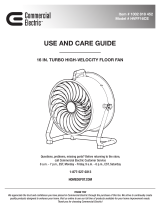
HARDWARE INCLUDED
NOTE: Hardware not shown to actual size.
NOTE: The hardware included is suitable for mounting to walls made of brick, solid concrete, or wood studs covered with drywall. If your
mounting situation is different, please consult a qualied installer or contact customer service at 1-877-527-0313 or visit
www.HomeDepot.com. For additional support, you can also call the manufacturer at 1-800-747-6558.
MM NN
AA BB CC – FF GG – JJ KK
RR
LL
OO PP
QQ
Part Description Quantity Part Description Quantity
AA Nylon anchor 3 JJ M8x50 mm bolt 4
BB Lag bolt with washer 3 KK M6/M8x22 mm spacer 4
CC M4x12 mm bolt 4 LL M4/M5x17 mm spacer 4
DD M5x12 mm bolt 4 MM M8x10 mm spacer 4
EE M6x12 mm bolt 4 NN M8x2.5 mm spacer 8
FF M8x25 mm bolt 4 OO M4/M5 washer 4
GG M4x30 mm bolt 4 PP M6/M8 washer 4
HH M5x30 mm bolt 4 QQ M8x14 mm bolt 8
II M6x35 mm bolt 4 RR 4 mm & 5 mm hex wrench 1 each
PACKAGE CONTENTS
A
C
B D
Part Description Quantity
A Wall plate unit 1
B Extended arm 2
C Bubble level 1
D TV bracket 2

6
Installation
1
Identifying the bolt diameter to use
To ensure proper mounting of the brackets to your TV, this
mounting system includes several sizes of bolts (CC – JJ), washers
(OO and PP), and spacers (KK – NN) that can be used in various
combinations. Combinations are determined by the back style of
the TV (at, curved, or recessed) and the diameter and depth of
those holes.
□ Select the bolt (CC – JJ) diameter to use by inserting the
various sized bolts (CC – JJ) (M4, M5, M6, and M8) into the
mounting holes in the back of your TV.
M5 M6 M8M4
OR OR OR
2
Identifying the bolt length to use
□ Insert a straw or toothpick into one of the mounting holes
on the back of your TV. If your TV is curved or recessed,
place the proper sized spacer (KK, LL, MM, or NN) on top of
one of the mounting holes rst.
□ Use a pencil to mark the depth of the mounting hole.
□ Determine the proper bolt length to use by comparing the
mark with the various bolts provided.
CAUTION: When the bolt is longer than the mark, choose
a shorter bolt.
FLAT
CURVED
RECESSED
3
Separating the TV plate
□ Use the hex wrench (RR) to remove the bolts (1) that hold
the TV plate on the wall plate unit (A). Save these bolts for
later.
A
RR
1
4
Marking the mounting holes
□ Use the holes in the wall plate unit (A) as a template to
mark the mounting hole locations for attaching the wall
plate unit (A) to the wall.
□ Use the bubble level (C) to ensure the mount will be level
before you drill holes.
C
A

7 HOMEDEPOT.COM
Please contact 1-877-527-0313 for further assistance.
Installation (continued)
5
Drilling mounting holes in concrete/
brick wall
If you are installing the mounting system into wood studs, proceed
to step 6.
CAUTION: Avoid drilling near electrical wiring and water
pipes. The mounting system must be attached to a weight
bearing wall. Failure to observe all safety precautions can
result in serious physical injury and/or property damage.
Consult a professional installer or call customer service if
you have any questions.
CAUTION: Do not drill into mortar between bricks or into
loose concrete.
CAUTION: Never drill into hollow brick.
□ Use 3/8 in. masonry bits to drill mounting holes in the
concrete approximately 2.50 in. (6.35 cm) in depth.
□ Insert nylon anchors (AA) into the pre-drilled holes. You
may have to use a hammer to gently tap the anchors fully
into the wall.
AA
Masonry
Drill Bit
6
Drilling mounting holes in wood studs
CAUTION: Avoid drilling near electrical wiring and water
pipes. The mounting system must be attached to a weight
bearing wall and must be installed directly onto the center
of the wood studs. Failure to observe all safety precautions
can result in serious physical injury and/or property
damage. Consult a professional installer or call customer
service if you have any questions.
CAUTION: Wood studs must be no smaller than 2 x 4 in.
in size and the surface covering no more than 5/8 in.
□ Use a commercially-available stud nder to locate the stud
centers in the wall. Studs are usually spaced 16 in. apart.
□ Use 7/32 in. (5.5 mm) wood drill bit to drill holes to a depth
of 2.50 in. (6.35 cm).
Wood
Drill Bit
7
Attaching the mounting arm to the
wall
□ Align the mounting arm holes with the pre-drilled holes in
the wall.
□ Attach the mounting arm (A) to the wall using lag bolts
with washers (BB). Tighten the bolts (BB) securely using a
Phillips screwdriver and a socket tool (not included).
A
BB
UP

8
Installation (continued)
8
Attaching the mounting plate to the
TV (VESA 100 and 200)
NOTE: If the back of the TV is not at, or the bolts are too
long, or there is interference between the TV bracket and
cable inlets, we strongly recommend the use of spacers.
This procedure describes how to attach the mounting plate to VESA
100 and 200 TVs. For VESA 300 to 600, proceed to step 9.
□ If necessary, align spacers (KK, LL, MM, or NN) over the
mounting holes on the back of your TV.
□ Position the wall plate (A) over the TV and attach using the
appropriately sized bolts (CC – JJ) and washers
(OO or PP).
CAUTION: Do not overtighten the bolts as this could
damage your TV.
KK/LL/MM/NN
A
OO/PP
GG/HH/II/JJ
A
OO/PP
100x100 / 200x200
100x100 / 200x200
CC/DD/EE/FF
NN
9
Attaching the mounting plate to the
TV (VESA 300/400/500/600)
□ Connect the extended arms (B) to the wall plate (A) using
screws (QQ). Then slide the TV brackets (D) onto the
assembly as shown.
□ If necessary, align spacers (KK, LL, MM, or NN) over the
mounting holes on the back of your TV.
□ Position the wall plate assembly over the TV and attach
using the appropriate sized bolts (CC – JJ) and washers
(OO or PP).
□ Secure the TV brackets (D) to the TV using screws (QQ).
CAUTION: Do not overtighten the screws as this could
damage your TV.
RR
D
D
B
A
B
QQ
QQ
OO/PP
QQ
GG/HH/II/JJ
KK/LL/MM/NN
OO/PP
CC/DD/EE/FF
NN

9 HOMEDEPOT.COM
Please contact 1-877-527-0313 for further assistance.
Installation (continued)
10
Attaching the TV to the wall plate
unit
CAUTION: Use two or more people to complete this step.
□ Align the wall plate (A1) with the end of the wall plate unit
(A2) and slide the tab (1) on the wall plate (A1) onto the top
edge of the wall plate unit (A2).
□ Attach the bottom end of the wall plate unit (A2) to the wall
plate (A1) using the bolts you removed in step 3.
□ Use the bubble level (C) and angle the TV as necessary to
ensure the TV is level before tightening in the next step.
A2
RR
A1
1
C
11
Securing the TV and wall mount in
place
□ Turn the handle clockwise until it stops (Fig. 1), and pull the
handle out from the wall mount (Fig. 2).
□ With the handle pulled out of the wall mount, turn the
handle counterclockwise (Fig. 3).
□ Push the handle back into the wall mount (Fig. 4), and turn
it clockwise to continue fastening the wall mount (Fig. 5).
Repeat these steps until the TV is secured tightly against
the wall mount.
NOTE: Keep the handle parallel with the wall. Otherwise the
handle may break as the TV is pushed back against the wall.
Fig. 1 Fig. 2 Fig. 3
Fig. 4 Fig. 5
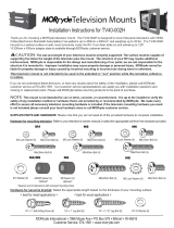
12
Adjusting the angle of the TV
□ Adjust the angle of the TV by loosening the handle (1) on
the wall plate assembly (A). Refer to the gure for the
various angle adjustments. Securely tighten the handle (1)
when you are nished.
NOTE: TVs between 26 in. and 60 in. can swivel up to 90
left or right, TVs 70 in. and larger can only swivel up to 50 in
either direction.
A
1
±5˚
±90˚
+5˚
-15˚

Questions, problems, missing parts? Before returning to the store,
call Commercial Electric Customer Service
8 a.m. - 7 p.m., EST, Monday-Friday, 9 a.m. - 6 p.m., EST, Saturday
1-877-527-0313
HOMEDEPOT.COM
For additional support, call the manufacturer at 1-800-747-6558.
Retain this manual for future use.
/