Page is loading ...

Installation Instructions A19BAC, A28AA
Issue Date 0403
®
A19BAC, A28AA Single and Two-Stage Space Thermostats
For Farm and General Purpose Applications
Application
The single-stage A19BAC and the
two-stage A28AA thermostats
incorporate single-pole double-
throw (SPDT) switches for
controlling automatic ventilation or
heating in livestock barns, poultry
houses, milk houses, brooder
houses and other buildings. The 30
to 110°F (0 to 43°C) and 0 to 140°F
(-15 to 60°C) temperature ranges
permit use for many space
applications.
IMPORTANT: The single-stage A19
and A28 thermostats are
intended to control equipment
under normal operating
conditions. Where failure or
malfunction of an A19 or A28
thermostat could lead to an
abnormal operating condition
that could cause personal
injury or damage to the
equipment or other property,
other devices (limit or safety
controls) or systems (alarm or
supervisory) intended to warn
of or protect against failure or
malfunction of the A19 or A28
thermostat must be
incorporated into and
maintained as part of the
control system.
!
CAUTION: Risk of
Property Damage. Do not
install A19 or A28 space
thermostats with general
purpose enclosures in any
type of agricultural
environment defined in NEC
Art. 547 where dust or dust
with water may accumulate or
where corrosive atmospheres
exist. Doing so may cause the
A19 or A28 thermostat to fail
and result in the loss of
temperature regulation and
damage to other property.
Operation
Figs. 4 and 5 illustrate the operation
of the A19. On a temperature
increase, the circuit between R and
Y closes. Simultaneously the R and
B circuit opens.
Figure 6 illustrates the operation of
the A28AA. On a temperature
increase, the circuit between R and
Y of the low stage switch (RY
L
)
closes. Simultaneously, the circuit
between R and B (RB
L
) opens.
On a further increase in
temperature, the high stage switch
operates and closes RY
H
while
simultaneously opening RB
H
.
The reverse sequencing takes
place on a temperature fall.
Installation
Mounting
Mount control to a flat surface with
screws through holes provided in
back of frame.
IMPORTANT: On rough mounting
surfaces use the top two
mounting holes only. When
these controls are mounted on
an uneven surface using
screws in all four holes, the
case can be twisted enough to
affect the thermostat’s
calibration and operation.
Mount the control where it is
exposed to the average
temperature of the controlled space.
Do not mount where it will be
affected by unusual heat or cold,
such as directly over an animal
stall, in sunlight, or on an outside
wall. Avoid locations near a door,
window or hay chute.
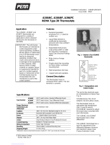
Fig. 1 -- Exterior view of Space
Thermostat
IMPORTANT: Do not dent or
deform the sensitive bulb of
this thermostat. A dent or
deformation will change the
calibration and cause the
thermostat to cycle at a
temperature lower than the
dial setting.
Adjustment
Knob adjustment or screwdriver slot
is supplied on the range screw. Dial
pointer is located on adjustment
stop bracket on knob and
screwdriver adjustment models.
Before removing the cover, verify
that all power to the thermostat and
associated equipment is turned off.
!
WARNING: Risk of
Electrical Shock. Disconnect
the power supply before
mounting and wiring to
prevent possible electrical
shock. On multiple circuit
units, more than one circuit
may have to be disconnected.
© 2003 Johnson Controls, Inc. 1
Part No. 996-238, Rev. C

Solid cover models are adjusted by
removing cover and moving dial so
that the setpoint is in line with the
dial pointer on the stop bracket.
(See Fig. 3.)
Convertible adjustment models can
be field converted from concealed
screwdriver slot adjustment to knob
adjustment or external screwdriver
slot adjustment. They are supplied
with a snap-in plug in the cover to
provide concealed screwdriver slot
adjustment. For knob adjustment
remove the snap-in plug and press
the knob onto the slotted shaft. For
external screwdriver slot adjustment
remove the snap-in plug.
The A28AA switch is stamped to
indicate the HI-TEMP switch and
the LO-TEMP switch.
Fig. 2 -- The Space Thermostats
with convertible adjustment have
a snap-in plug in the cover, built-
in screwdriver slot and a knob
for field installation.
A high temperature adjustment stop
is supplied on the thermostats. (See
Fig. 3.) If adjustment stop is
required:
1. Set dial to temperature at
which stop is desired.
2. Remove cover from thermostat.
3. Loosen the adjustment stop
screw, slide the screw to the
front of the thermostat against
the plastic stop cam behind the
dial and tighten the screw. (See
Fig. 3.)
Sometimes an exact stop
setting is not possible and stop
must be set to the closest step
corresponding to dial setting
required.
4. Turn dial to setpoint desired.
5. Replace cover.
Wiring
!
WARNING: Risk of
Electrical Shock. Disconnect
the power supply before
mounting and wiring to
prevent possible electrical
shock. On multiple circuit
units, more than one circuit
may have to be disconnected.
All wiring should conform to local,
national, and regional codes. Use
copper conductors only. Do not use
on applications where electrical
ratings exceed ratings shown on the
thermostat’s cover label.
See Figs. 4 through 11 for typical
wiring applications.
Note: Use terminal screws
furnished (8-32 × 1/4 in. binder
head). Substitution of other screws
may cause problems in making
proper connections.
Checkout Procedure
Before leaving the installation,
observe at least three complete
operating cycles to be sure that all
components are functioning
correctly.
Check for correct operation in the
following manner.
1. A19BAC -- Ventilating or
Cooling: Turn dial clockwise to
a setting above space
temperature. Fan or cooling
system should be off. When
you turn the dial
counterclockwise, the fan or
cooling system should turn on
approximately at the dial
setting.
A19BAC -- Heating: Turn dial
clockwise above the space
temperature; the heating unit
should be on. When you turn
the dial counterclockwise, the
heating unit should turn off
approximately at the dial
setting.
2. A28AA -- If wiring is similar to
Fig. 8, fan should start at
approximately space
temperature and should
change to high speed as the
dial is turned counterclockwise
to a lower temperature setting.
If similar to Fig. 9, the damper
should open as the dial is
turned counterclockwise. The
devices should act in reverse
sequence when the dial is
turned clockwise to a higher
setting.
3. If control devices do not
operate in the manner
described above, check all
wiring for short circuits and
tightness of wiring
connections. If controlled
devices operate in reverse
(start in high or fully open
position), check wiring.
Repairs and Replacement
Field repairs must not be made. For
replacement thermostat contact the
nearest Johnson Controls
distributor.
Adjustment Stop Bracket
with Slot and Screw
Fig. 3 – All models have a screw
type adjustment stop. Loosen
and move stop screw to the stop
setting desired. Tighten screw
after setting is made.
2 A19BAC, A28AA Installation Instructions

Electrical Ratings
A28AA* A19BAC
Volts, AC 120 208 240 277 120 208 240 277
Full Load Amp
16.0 9.2 8.0 -- 16.0 9.2 8.0 --
Locked Rotor Amp
96.0 55.2 48.0 -- 96.0 55.2 48.0 --
Non-Inductive Amp
16.0 9.2 8.0 7.2 16.0 16.0 16.0 16.0
SPDT
SPST
16.0 9.2 8.0 7.2 22.0 22.0 22.0 22.0
Pilot Duty
125 VA, 24 to 277 VAC 125VA, 24 to 600 VAC
* Max connected load not to exceed 2000 VA.
*Disconnecting means and overload protection as required.
Fig. 4 – A19BAC typical heating control circuit.
Fig. 5 – A19BAC typical ventilating or cooling control circuit.
Fig. 6 – Switch action of the A28AA two-stage control.
RB
H
, RY
H
indicate HI-TEMP. RB
L
, RY
L
indicate LO-TEMP. D
is the differential between stages.
A19BAC, A28AA Installation Instructions 3

Controls Group
507 E. Michigan Street
P.O. Box 423 Published in U.S.A.
Milwaukee, WI 53202 www.johnsoncontrols.com
4 A19BAC, A28AA Installation Instructions
/