Page is loading ...

Installation Instructions A19ANC/ANF/APC
Issue Date 0303
© 2003 Johnson Controls, Inc. 1
Part No. 3530, Rev. H
®
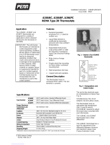
A19ANC, A19ANF, A19APC
NEMA Type 3R Thermostats
Application
The A19ANC, A19ANF and
A19APC thermostats are
designed for a variety of
applications where rainproof
enclosures are necessary or
desirable.
IMPORTANT: The A19 Series
thermostats are intended to
control equipment under
normal operating conditions.
Where failure or malfunction
of an A19 thermostat could
lead to an abnormal
operating condition that
could cause personal injury
or damage to the equipment
or other property, other
devices (limit or safety
controls) or systems (alarm
or supervisory) intended to
warn of or protect against
failure or malfunction of the
A19 thermostat must be
incorporated into and
maintained as part of the
control system.
Features
•Rainproof gasketed
enclosure is U.L. Listed for
outdoor use.
•Liquid-filled element is
unaffected by barometric
pressure and cross-ambient
temperatures.
•Dependable field proven,
snap-acting switch is rated
for inductive or resistance
loads (See Electrical Ratings
table).
•Wide choice of range
options.
•Simple strain-free mounting
on three rubber cushioned
mounting feet.
•High temperature dial stop.
•Copper bulb well available.
General Description
The thermostats have an
enclosed SPDT switch. The red
terminal is common.
Fig. 1 -- Interior of an A19ANC
thermostat.
Red
(Common)
Blue
h
Yellow
Red to Blue
Opens on
Temperature
Increase
Red to Yellow
Closes on
Temperature
Increase
Fig. 2 – Designations and
Switch Action
The red to blue terminals open
on a temperature increase (See
Fig. 2).
Simultaneously, the circuit
between red and yellow closes.
The thermostats have an
adjustable high temperature
stop. A special wrench
(Part 836-61) required to adjust
the keyed stop is provided with
each thermostat.
The A19ANC and A19ANF
thermostats have a fixed
differential.
The A19APC thermostat has a
lever for adjustment of the
differential between minimum
and maximum values (See
Product Selection Chart).
Specifications
A19ANC SPDT Switch Action, Standard Differential (Fixed)
A19ANF SPDT Switch Action, Close Differential (Fixed)
Type Number
A19APC SPDT Switch Action, Standard Differential (Adjustable)
Range, Maximum
Temperature and
Differential* See Selection Chart
Capillary .062” (1.6 mm) O.D. Standard Length is 10’ (3 m)
Enclosure Rainproof with Gasketed Cover (NEMA 3R)
Finish U.L. Listed Outdoor Gray Enamel
Material .062” (1.6 mm) Cold Drawn Steel
Switch Snap-Acting Contacts in Dust Protected Enclosure
Conduit Opening Welded ¾” Female Connector
Wiring Connections Screw Type Terminals
Mounting Three Rubber Cushioned Mounting Feet
Shipping Weight 2.3 Lb (1.0 kg)
*Differential is based on direct bulb immersion in liquid at 1F° (0.6C°) per minute rate of change.

2 A19ANC/A19ANF/A19APC Installation Instructions
Optional Constructions
Sensing Elements
See Product Selection Chart for
standard capillary lengths. Other
lengths are available. Contact a
Johnson Controls
representative.
Bulb Well
Copper bulb wells with 1/2 in.
NPT brass connectors are sold
separately. See Product
Selection Chart for ordering
information. For special
applications requiring a
connector made with a different
metal, contact a Johnson
Controls representative for
availability.
Installation
!
WARNING: Risk of
electrical shock.
Disconnect power supply
before wiring connections
are made to avoid possible
electrical shock.
!
CAUTION: Risk of
equipment damage.
Disconnect power supply
before wiring connections
are made to avoid damage
to the equipment.
Note: Use terminal screws
furnished (8-32 × 1/4 in. binder
head). Do not substitute screws
of a different size. Make all
wiring connections using copper
conductors only, and in
accordance with the local,
national, and regional
regulations.
Indoors, mount the thermostat in
any position by means of three
mounting feet. When the
thermostat will be exposed
directly to the outdoor weather,
mount the thermostat with the
electrical conduit, capillary
fittings, and drain hole facing
downward as illustrated in Fig. 1.
Ambient rating (not bulb
maximums) 140°F (60°C).
Fig. 3 – Bulb well dimensions
IMPORTANT: Do not dent or
deform the sensing bulb of
this control. A dent or
deformation will change the
calibration and cause the
control to cycle at a
temperature lower than the
dial setting.
Where the capillary is exposed
and subject to possible
mechanical damage some
means of protection should be
provided. The capillary outlet is
designed to permit the capillary
to be run through 1/2 in. thin wall
or flexible conduit. Remove the
capillary outlet seal nut. (See
Fig. 4.) Push the bulb and
capillary through a conduit
coupling or suitable hose fitting
and on through the conduit or
hose. By tightening the coupling
to the 1/2 in. female capillary
outlet fitting, the seal around the
capillary will be maintained and
the conduit or hose will be rigidly
attached to the enclosure.
Adjustments
!
WARNING: Risk of
electrical shock. To avoid
the risk of electrical shock,
disconnect the power
supply before making any
adjustments to avoid
possible electrical shock.
Product Selection Chart
Product
Number Range
°
°°
°F
(
°
°°
°C
)
Differential
F°
°°
°
(
C°
°°
°
)
Maximum Allowable
Tem
p
°
°°
°F
(
°
°°
°C
)
Capillary Length
Ft. (m) Bulb Size Bulb Well
(if required)
A19ANC-1 0 to 150
(-18 to 66) 5
(2.8) 190
(88) 10
(3) 0.290 x 2 ½” WEL11A-601R
A19ANC-2 100 to 250
(38 to 121) 6
(3.3) 290
(143) 10
(3) 0.290 x 2 ½” WEL11A-601R
A19ANC-3 200 to 350
(93 to 177) 5
(2.8) 390
(199) 10
(3) 0.366 x 2 ¼” WEL16A-601R
A19ANF-3 20 to 90
(-6.7 to 32) 2
(1.1) 130
(54) 10
(3) 0.366 x 2 5/8” WEL16A-601R
A19APC-1 20 to 90
(-6.7 to 32) 3.5 to 14
(1.9 to 7.8) 140
(60) 6
(1.8) 0.375 x 5” WEL14A-603R

A19ANC/A19ANF/A19APC Installation Instructions 3
Fig. 4 – Typical installation where capillary protection is required
To change the temperature
setpoint, remove the cover, and
rotate the dial to the desired
setpoint with a screwdriver.
Replace cover, and verify that
gasket is sealed.
Adjustable Differential
(A19APC only)
Models with adjustable
differential are factory set at
minimum differential. To adjust,
move the lever between
maximum and minimum.
Adjustable Maximum Setpoint
Stop
To change the stop setting,
loosen the two screws in the dial
plate with the wrench included
with the control. Turn the dial so
the pointer indicates the stop
setting.
Move the stop (located behind
the dial plate) against the stop
bracket. Tighten screws to lock
the stop in position.
High cutout stop can be set
between 55F° (31C°) above the
bottom of the range and the top
of the range. Example: The high
temperature stop can be set
between 255 to 350°F (124 to
277°C) on a control with a range
of 200 to 350°F (93 to 177°C).
Checkout Procedure
Before leaving the installation,
observe at least three complete
operating cycles to be sure that
all components are functioning
correctly.
Repairs and Replacement
Field repairs must not be made
except for replacement of the
bulb well and cover. For a
replacement thermostat, bulb
well, or cover, contact the
nearest Johnson Controls
distributor.

4 A19ANC/A19ANF/A19APC Installation Instructions
Performance specifications appearing herein are nominal and are subject to accepted
manufacturing tolerances and application variables.
UL Guide No. XAPX
File E6688
Controls Group
507 E. Michigan Street
P.O. Box 423 Published in U.S.A.
Milwaukee, WI 53201 www.johnsoncontrols.com
/