Page is loading ...

European Refrigeration Controls Catalogue
Catalog Section 1
Product Bulletin A19A
Issue 03/03/2003
© 2003 Johnson Controls Inc. Catalogue Section 1
Order No. PD-A19A-E
PSC9705
I
ntroduction
These thermostats are designed for
refrigeration, cooling, heating, ventilation and
air-conditioning applications. Standard models
are provided for remote sensing or room
sensing. Models with manual reset are
available for low or high limit functions.
D
escription
These thermostats are available with fixed or
adjustable differential. The various control
ranges cover a broad range of temperature
applications with a minimum number of models.
On request a built-in high or low limit stop is
possible and can be adjusted quickly and easily
in the field. All models have a universal way of
adjustment. For this purpose a knob and sealing
cap are enclosed.
All A19 style 1 wholesaler code models have a
bulb clamp plus screw also enclosed.
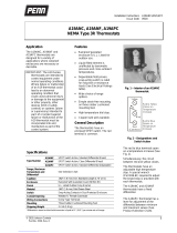
A19A capillary thermostat
A19B space thermostat
Feature and Benefits
Liquid filled sensing element
No cross ambient temperature problems
Contact differential over the whole range
Dust tight Penn switch Prevents pollution of the contacts by
electrostatic influences.
Trip free manual reset Override is not possible in the control function
Front adjustment Less mounting space required.
Series A19A/A19B/A19D
Thermostats for Refrigeration, Cooling, Heating, Ventilation
and Air-conditioning

A19A
Issue 03/03/2003
Catalogue Section 1 © 2003 Johnson Controls Inc.
Order No. PD-A19A-E
2
N
ote
These controls are designed for use only
as operating controls. Where an operating
control failure would result in personal injury
or loss of property it is the responsibility of
the installer to add devices or systems that
protect against, or warn of, control failure.
SPDT contacts are standard on all models.
Instruments have compact sizes. Types
A19ACC and A19ADC have a trip-free manual
reset . Reset button must be pressed and
released. Contact cannot be blocked in closed
position. All types have VDE and SEV approval.
To facilitate ordering, wholesaler codes have
been added on some universal models.
All models are provided with a separate knob
and sealing cap.
T
ype number matrix
A19AAC capillary thermostat, fixed differential.
A19AAF capillary thermostat, special close
fixed differential.
A19ABC capillary or immersion thermostat,
adjustable differential.
A19ACC capillary thermostat, lock-out low
with manual reset.
A19ADC immersion thermostat, lock-out high
with manual reset.
A19BAC space thermostat, fixed differential.
A19BBC space thermostat, adjustable
differential.
A19DAC strap-on thermostat.
A19DAF strap-on thermostat
A
djustment
1. Models “set low” (refer to cover label)
The dial indicates the low switch point
(1 - 2 open, 1 - 3 closed).
The high switch point (1 - 2 closed,
1 - 3 open) is obtained by adding the
differential to the low switch point.
2. Models “set high” (refer to cover label)
The dial indicates the high switch point
(1 - 2 closed, 1 - 3 open). The low switch
point (1 - 2 open, 1 - 3 closed) is obtained by
deducting the differential from the high switch
point.
Exception: Type A19ADC, dial indicates high
switch point ( 1 - 3 closed, 1 - 2 open).
N
ote
The standard screwdriver adjustment can
be converted easily in the field to knob
adjustment. Also concealing of adjustment
and scale is possible after installation.
C
ontact functions
Types A19AAC,
A19AAF, A19ABC,
A19BAC, A19BBC,
A19DAC
Fig. 1
1-2 closes on temperature increase
Type A19ACC
Fig. 2
1-2 opens on temperature decrease
Type A19ADC
Fig.3
1-2 opens on temperature increase
R
epair and replacement
Repair is not possible. In case of an improperly
functioning control, please check with your
nearest supplier. When contacting the supplier
for a replacement you should state the
type/model number of the control. This number
can be found on the data plate or cover label.
1
23
θ
>
1
23
θ
<
1
23
θ
>

A19A
Issue 03/03/2003
© 2003 Johnson Controls Inc.
Catalogue Section 1
Order No. PD-A19A-E
3
S
ensor styles
Fig. 4
Style 1a (drawn bulb)
Fig.5
Style 1b swaged bulb, can be used with
closed-tank connector FTG13A-600
½" x 14 NPT
33.3 60
Fig. 6
Style 4h
½" x 1 4 NPT
58.3
60
Fig. 7
Style 2
Fig. 8
Style 20
Fig. 9
Style 3 (coil)
B
ulb size and finish, bulb wells
Range (°C) Style Bulb size
(mm)
Finish Bulb well (optional)
-35 to +10 1b 9.5 x 110 Tin-plated WEL14A602R
-35 to +10 3 - Stainless Steel -
-5 to +28 1b 9.5 x 135 Tin-plated WEL14A603R
-5 to +28 3 - Stainless Steel -
-35 to +40 1b 9.5 x 110 Tin-plated WEL14A602R
-35 to +40 3 - Stainless Steel -
0 to 13 1a 9.3 x 80 - WEL16A601R
0 to 43 3 - Stainless Steel -
1 to 60 1b 9.5 x 115 - WEL14A602R
5 to 32 1b 9.5 x 155 Tin-plated No bulb well available
10 to 95 1a 7.4 x 75 - WEL11A601R
40 to 120 1b 9.5 x 100 - WEL14A602R
35 to 150 1a 5 x 265 - No bulb well or closed tank
connector possible
90 to 290 1a 5 x 155 - No bulb well or closed tank
connector possible

A19A
Issue 03/03/2003
Catalogue Section 1 © 2003 Johnson Controls Inc.
Order No. PD-A19A-E
4
T
ype number selection table:
Range
( °C)
Diff.
(K)
Bulb
style
Setting
(see page 2
adjustment)
Cap.
length
Max.
bulb
temp.
Wholesaler
code
Orde
r
number
Type A19AAC Capillary thermostat, fixed differential
-35 to +10 2.5 1b set low 2 m 60 °C A19AAC-9102
-5 to +28 2 1b set low 2 m 60 °C A19AAC-9005
-5 to +28 2 1b set low 5 m 60 °C A19AAC-9124
1 to 60 2 1b set low 3 m 85 °C A19AAC-9127
40 to 120 3.5 1b set high 2 m 145 °C A19AAC-9009
35 to 150 4 1a set high 2 m 180 °C A19AAC-9107
90 to 290 5.5 1a set high 2 m 290 °C A19AAC-9108
Type A19ABC Capillary or immersion thermostat, adjustable differential
-35 to +40 2.8 to 8 1b set low 3.5 m 60 °C A19-A4
A19ABC-9037
-35 to +40 2.8 to 8 1b set low 6.5 m 60 °C A19-A5
A19ABC-9036
-35 to +10 2.8 to 11 1b set low 2 m 60 °C A19-A1
A19ABC-9103
-5 to +28 2 to 8 1b set low 2 m 60 °C A19-A2
A19ABC-9104
1 to 60 2 to 8 1b set low 5 m 85 °C
A19ABC-9117
1 to 60 2 to 8 1b set low 3 m 85 °C A19-A3
A19ABC-9116
10 to 95 3.5 to 13 1a set high 3.5 m 115 °C
A19ABC-9106
40 to 120 3.5 to 13 2 set high - 145 °C
A19ABC-9011
bulb well incl.
40 to 120 3.5 to 13 4h set high 2 m 145 °C
A19ABC-9012
bulb well incl.
Type A19ACC Capillary thermostat, lock-out low with manual reset
-35 to +10
6
M 1b set low 2 m 60 °C
A19ACC-9100
-35 to +10 N
6
M 1b set low 3.5 m 60 °C
A19ACC-9105
-35 to +10 N
6
M 1b set low 5 m 60 °C
A19ACC-9111
-35 to +10 N
6
M 1b set low 6.5 m 60 °C
A19-F
A19ACC-9116
-5 to +28
4
M 1b set low 2 m 60 °C
A19ACC-9101
-5 to +28
4
M 1b set low 5 m 60 °C
A19ACC-9103
-5 to +28
4
M 1b set low 3 m 60 °C
A19ACC-9107
Type A19ADC immersion thermostat, lock-out high with manual reset
40 to 120
7
O
2
set high - 145 °C
A19ADC-9200
bulb well incl.
Type A19AAF Capillary thermostat, close, fixed differential
0 to 10 1.5 1a set low 2 m 80 °C
A19AAF-9101
0 to 10 1.5 1a set low 2 m 80 °C A19-M P
A19AAF-9102
5 to 32 0.75 1b set high 2 m 60 °C
A19AAF-9103
M Indicates temperature increase above cut-out
point to make reset possible.
N Low limit stop factory set +2.5 °C may be
removed in the field.
O Indicates temperature decrease below cut-
out point to make reset possible.
P Milk-cooler thermostat.

A19A
Issue 03/03/2003
© 2003 Johnson Controls Inc.
Catalogue Section 1
Order No. PD-A19A-E
5
T
ype number selection table:
Range
( °C)
Diff.
(K)
Bulb
style
Setting
(see page 2
adjustment)
Cap.
length
Max.
bulb
temp.
Wholesaler
code
Orde
r
number
Type A19BAC Space thermostat, fixed differential
-35 to +10 2.5 3 set low - 60 °C
A19-B1
A19BAC-9250
-5 to
+28
2 3 set low - 60 °C
A19-B2
A19BAC-9251
0 to 43
2 3 set high - 60 °C
A19-B3
A19BAC-9001
Type A19BBC Space thermostat, adjustable differential
-35 to +40 2.8/8 3 set low - 60 °C A19-B4
A19BBC-9275
Type A19DAC, Strap-on thermostat, fixed differential
40 to 120 4.5 20 set high - 145°C
A19DAC-9001
92 to 116 2 20 set high - 145°C
A19DAF-9001
Note: If what you need is not in the type number selection table, then please contact your
representative.

A19A
Issue 9811
Catalogue Section 1 © 2003 Johnson Controls Inc.
Order No. PD-A19A-E
6
A
ccessories (optional)
3
2
A
B
1
C
Order no. Dimension A Dimension
B Dimension C
Internal
WEL11A601R 60 mm 118 mm 7.3 mm
WEL14A602R 125 mm 171 mm 9.8 mm
WEL14A603R 147 mm 193 mm 9.8 mm
WEL16A601R 71 mm 117 mm 9.5 mm
1. Bushing
2. Set screw
3. Adapter, 1/2"-14 NPT
Fig. 10
Bulb well (brass, copper pipe)
76
63
27
ø 5.5 (3x)
1/2"-14 NPT
11.5
Fig. 11
Duct flange to be used with closed-tank
connector FTG13A-600R.
Order number T-752-1001
3 4 3 5 621
1. Style 1b bulb support tube
2. Packing nut
3. Washer
4. Packing
5. Adapter, 1/2"-14 NPT
6 . Bulb
Fig. 12
Closed-tank connector
Order number FTG13A-600R

A19A
Issue 03/03/2003
© 2003 Johnson Controls Inc.
Catalogue Section 1
Order No. PD-A19A-E
7
D
imensions (mm)
32
13
19
75
19
7
55
40
13
125
46.5
21.5
6
16
28
3.6
1
2
4
3
1 Reset lever
2 Knob packed separately with the control
3 22.3 mm dia. cable inlet hole for PG-16
4 Earth screw
Fig. 13

A19A
Issue 9811
Catalogue Section 1 © 2003 Johnson Controls Inc.
Order No. PD-A19A-E
8
S
pecifications
CE Conformit
y
According to low voltage directive and EMC directive
Operatin
g
ran
g
e
-35 to +290 °C. See type number selection table.
Differential
See type number selection table.
Differential ad
j
ustments
Controls with adjustable differential (types A19ABC and A19BBC) have
an adjustment lever under the cover.
Senso
r
st
y
les
Styles 1a, 1b, 2, 3, 4h, and 20 (see drawings page 3)
Electrical ratin
g
s
~15(8) A, 230 V; except A19AAF and A19DAF: ~15(3) A 230 V, and
A19ABC-9036/9037: ~15(5) A 230 V
Ambient temp. limits
-35 to +55 °C
Conduit openin
g
22.3 mm diam. hole for PG-16 connector
Material
Case 1.75 mm cold-rolled zinc plated steel
Cover 1.5 mm ABS plastic
Protection Class
IP30
Shippin
g
wei
g
ht
Individual pack 0.4 kg
Overpack 10 kg (24 pcs)
Dimensions
(see dimension drawing)
The performance specifications are nominal and conform to acceptable industry standards. For applications at conditions beyond
these specifications, consult the local Johnson Controls office or representative. Johnson Controls shall not be liable for damages
resulting from misapplication or misuse of its products.
Johnson Controls International, Inc.
Headquarters: Milwaukee, WI, USA
European Headquarters: Westendhof 8, 45143 Essen, Germany
European Factories: Lomagna (Italy), Leeuwarden (The Netherlands) and Essen (Germany)
Branch Offices: Principal European Cities.
This document is subject to change Printed in Europe

1
PSC9720
SHT067N600(003)
Instruction sheet
Litho in the Netherlands 9712EP
A19
ENGLISH
READ THIS INSTRUCTION SHEET CAREFULLY BEFORE
INSTALLING, RETAIN IT SAFELY FOR FUTURE REFER-
ENCE.
1 Setpoint dial
2 Knob for adjustment (separate packed)
3 Cap for concealed adjustment (separate packed)
4 Differential lever (adjustable differential models only)
5 Cover (not on models A19AGC, A19AGF and BGC models)
The A19 is a temperature control designed to sense temperatures.
According to EN 60730 it is a type 1 action, independently mounted
control, suitable for surface mounting on a plane surface and for use in
normal pollution situation. The A19AGC,A19AGF and A19BGC mod-
els are incorporate controls.
These controls are designed for use only as operating controls. Where
an operating control failure would result in personal injury or loss of
property, it is the responsibility of the installer to add devices or systems
that protect against, or warn of, control failure.
Installation
DO NOT TURN SEALED SCREWS
!
Disconnect from power supply before the cover is removed.
!
For A19AGC, A19AGF and A19BGC Disconnect power supply
before adjusting the control.
Wiring
All wiring should conform to local codes and must be carried out by
authorized personnel only. When using multi stranded wire apply a
cable ferrule to the cable end.
Check out procedure
Before leaving the installation observe at least three complete operat-
ing cycles to be sure that all components are functioning correctly. If not
contact your supplier.
!
180°
T min.: - 35 °C
T max.: + 55 °C
1
4
5
23
2
rdfguhlj;ko
b n b n , m/,. m
fchfchhbkjlkjn
(3x)
M 4x6
0.5 to 4 mm
(20-12 AWG)
2
1
3
1
3
2
1
3
2
°C
Set Low
SP
1
2
3
1
2
3
°C
Set High
SP
1
3
2
1
3
2
°C
ACC
SP
≥ 6k (-35 to +10°C)
≥ 4k ( -5 to +10°C)
1
2
3
1
2
3
°C
ADC
SP
≥ 7k ( +40 to 120°C)
1
3 2
θ >
AAC, AAF, ABC
AGF, BAC, BBC
1
2 3
θ >
ADC
1
2 3
θ <
ACC
LISEZ ATTENTIVEMENT CES INSTRUCTIONS AVANT DE
COMMENCER L’INSTALLATION ET CONSERVEZ- LES
POUR VOUS Y REFERER ULTERIEUREMENT
1. Cadran de consigne
2. Bouton de réglage (emballé séparément)
3. Bouchon pour réglage caché (emballé séparément)
4. Levier de différentiel (uniquement pour modèles avec différentiel
réglable)
5. Couvercle (pas sur les modèles A19AGC, A19AGF ni BGC)
Le modèle A19 est un régulateur de température destiné à détecter les
températures
D’après la norme EN 60730 c’est un régulateur indépendant, action
type 1, conçu pour un montage sur surface plane et utilisé dans des
environnements normalement pollués. Les modèles A19AGC, A19AGF
et A19BGC sont des commandes incorporées.
Cet appareil est destiné à assurer des fonctions de régulation. Lorsque
la panne ou le mauvais fonctionnement de ce dernier risque d'entraîner
des dommages matériels ou corporels, il est de la responsabilité de
l'installateur de prévoir des organes de sécurité indépendants afin de
ne pas utiliser le régulateur en équipement de sécurité.
Installation
NE PAS TOURNER LES VIS SCELLEES
!
Couper l’alimentation électrique avant d’enlever le couvercle.
!
Pour A19AGC, A19AGF et A19BGC, coupez l’alimentation avant
de régler les commandes.
Câblage
Tous les raccordements doivent être conformes aux normes en
vigueur et ne peuvent être réalisés que par du personnel autorisé.
En cas d’utilisation de câble souple multi-brins, utiliser un embout à
sertir.
Procédure de contrôle
Après avoir terminé l’installation, observez au moins trois cycles
complets de fonctionnement pour s’assurer que tous les composants
fonctionnent correctement. Si cela n’est pas le cas, contactez votre
fournisseur.
!
FRANÇAIS
BITTE LESEN SIE DIESE ANWEISUNGEN VOR DER IN-
STALLATION SORGFÄLTIG DURCH UND BEWAHREN SIE
SIE ZUR WEITEREN VERWENDUNG AUF.
1 Sollwertskalenscheibe
2 Einstellknopf (separat verpackt)
3 Aufsatz für verdeckte Einstellung (separat verpackt)
4 Differentialhebel (Nur einstellbare Differentialmodelle)
5 Deckel (Nicht bei Modellen A19AGC, A19AGF und A19BGC)
Der A19 ist ein Temperaturregler zum Fühlen von Temperaturen.
Dieses ist entsprechend EN 60730 ein, Wirkungsweise Typ 1, Unab-
hängig montiertes Regel- und Steuergerät Geeignet als Aufbaugerät,
z. B. für Wandmontage und für Anwendung in Umgebungsbedingun-
gen mit üblicher Verunreinigung. Bei den Modellen A19AGC, A19AGF
und A19BGC handelt es sich um Einbauregler.
Diese Regler sind ausschließlich zur Verwendung als Bedienungs-
elemente vorgesehen. In Situationen, in denen das Versagen eines
Bedienungselements Personenschäden oder Sachverluste nach sich
ziehen kann, ist der Installateur dafür verantwortlich, entsprechende
Vorrichtungen oder Systeme einzubauen, die einem Regelversagen
entgegenwirken oder die als entsprechende Frühwarnsysteme die-
nen.
Montage
PLOMBIERSCHRAUBEN NICHT ANZIEHEN!
!
Vor dem Entfernen des Deckels Spannung abschalten.
!
A19AGC, A19AGF und A19BGC: Von Stromversorgung trennen,
bevor der Regler eingestellt wird.
Verdrahtung
Alle Verdrahtungen müssen den am Einsatzort geltenden Vorschriften
entsprechen und sind ausschließlich dazu befugten Personen
vorbehalten.Bei Vewendung feindrätiger Leitungen sind
Adernendhülsen zuverwenden.
Überprüfung
Vor dem Verlassen der Anlage sollten Sie diese mindestens drei
Betriebszyklen beobachten und überprüfen, daß alle Komponenten
ordnungsgemäß funktionieren. Sollte dies nicht der Fall, wenden Sie
sich bitte an Ihren Händler.
!
DEUTSCH
NEEM DEZE INSTRUCTIES GRONDIG DOOR ALVORENS U
BEGINT MET HET INSTALLEREN EN BEWAAR ZE VOOR
TOEKOMSTIG GEBRUIK
1 Temperatuur instellingsschijf
2 Knop voor temperatuur afstelling (apart verpakt)
3 Kap voor afdekking van temperatuurinstelling (apart verpakt)
4 Differentie instellingshendel (alleen bij modellen met verstelbare
differentie)
5 Deksel (niet op A19AGC, A19AGF en A19BGC modellen)
De A19 is een thermostaat ontworpen voor het meten van temperatu-
ren
Volgens EN 60730 is het een, type 1 aktie, onafhankelijk te monteren
apparaat, geschikt voor montage op een plat oppervlak en geschikt
voor gebruik in een normaal vervuilde omgeving. De A19AGC,
A19AGF en A19BGC modellen zijn in te bouwen apparaten.
Deze apparaten zijn alleen ontworpen voor gebruik als regelaar. Als
een foutieve werking van de regelaar persoonlijk letsel of schade kan
veroorzaken, moet de installateur beveiliging of alarm apparatuur
aansluiten die aangeeft dat de regelaar niet funktioneert.
Montage
NIET DRAAIEN AAN AFGELAKTE SCHROEVEN
!
Schakel de voedingsspanning af voordat het deksel wordt verwij-
derd
!
Voor A19AGC,A19AGF en A19BGC : Sluit de voedingsspanning
af voordat de regelaar wordt afgesteld.
Bedrading
De installatie, de elektrische aansluiting en de instellingen dienen
overeen te stemmen met de plaatselijke voorschriften en mogen enkel
worden uitgevoerd door bevoegd personeel.
Indien een draad met flexibele kern wordt toegepast dient het uiteinde
van de draden te worden voorzien van een ader eindhuls.
Controleprocedure
Controleer, voordat u de installatie zelfstandig laat werken, gedurende
ten minste drie complete werkcycli of alle onderdelen correct werken.
Werkt de installatie niet correct, neem dan contact op met uw leveran-
cier.
!
LEA DETENIDAMENTE ESTA HOJA DE INSTRUCCIONES
ANTES DE REALIZAR LA INSTALACION Y GUARDELA
PARA FUTURAS CONSULTAS
1 Cuadrante para fijar el punto de control
2 Botón de ajuste (embalado por separado)
3 Casquillo para ajuste oculto (embalado por separado)
4 Palanca diferencial (sólo en modelos con diferencial ajustable)
5 Cubierta (no en los modelos A19AGC, A19AGF y BGC)
El A19 es un control de temperatura diseñado para detectar tempera-
turas.
Según EN 60730, es un, acción tipo 1 control montado independien-
temente adecuado para montaje en superficie en una superficie plana
y para uso en condiciones de contaminación normal.
Los modelos A19AGC, A19AGF y A19BGC son controles incorpora-
dos
Estos controles están diseñados para ser utilizados solamente como
controles de funcionamiento. En los casos en que un fallo de control
de funcionamiento pudiera producir daños personales o a propieda-
des, es responsabilidad del instalador añadir los dispositivos o siste-
mas que protejan o adviertan de los fallos de control.
Instalación
NO GIRE LOS TORNILLOS SELLADOS.
!
Desconectar la corriente antes de quitar la tapa.
!
Para A19AGC, A19AGF y A19BGC, desconecte la fuente de
alimentación antes de ajustar el control.
Cableado
Todo el cableado debe cumplir las normativas locales y debe realizar-
se solamente por el personal autorizado. Cuando se utiliza cable
flexible aplicar terminales en los extremos.
Procedimiento de comprobación
Antes de finalizar la instalación, observe por lo menos tres ciclos de
operación completos para asegurarse que todos los componentes
estén funcionando correctamente. Sino es así, póngase en contacto
con su proveedor.
!
ESPAÑOL
GERE ATTENTAMENTE LE ISTRUZIONI PRIMA DELL’IN-
STALLAZIONE E lSERVARE PER FUTURE CONSULTAZIO-
NI
1 Scala del valore di riferimento
2 Manopola di regolazione (fornita a parte)
3 Cappellotto per regolazione protetta (fornito a parte)
4 Leva differenziale (solo modelli a differenziale variabile)
5 Coperchio (eccetto modelli A19AGC, A19AGF e BGC)
Il dispositivo A19 è un regolatore della temperatura in grado di rilevare
le temperature.
Secondo le EN 60730 è un, azione tipo 1 Regolatore montato indipen-
dentemente, adatto per montaggio su una superficie piatta e per uso
in situazioni di normale inquinamento. I modelli A19AGC, A19AGF e
A19BGC sono comandi incorporati.
Questi dispositivi hanno esclusivamente la funzione di comandi. Se un
comando può provocare danni alle persone o alle cose, è responsabi-
lità dell’installatore aggiungere gli opportuni dispositivi o sistemi di
protezione o di segnalazione dello stato di guasto del comando stesso.
Installazione
NON SBLOCCARE LE VITI SIGILLATE
!
Staccare l’alimentazione prima di togliere il coperchio.
!
Per A19AGC, A19AGF e A19BGC: togliere tensione prima di
regolare il comando.
Cablaggio
Il cablaggio deve essere conforme alle normative locali ed essere
eseguito esclusivamente da personale autorizzato. Quando si usa un
cavo con filo a trefoli occorre applicare un capocorda alla fine di ogni
filo.
Messa in funzione
Prima di concludere l’installazione, osservare almeno tre cicli operativi
completi per accertare il corretto funzionamento di tutti i componenti.
In caso di irregolarità, contattare il proprio fornitore.
!
ITALIANO
NEDERLANDS
Specification Description Spezifikation
Specificatie Especificación Specifiche
Especificação Specifikationer Erittely
Beskrivelse Spesifikasjoner Πρïδιαγραæές
Technická data
Mounting Montage Montage
Montage Montaje Montaggio
Montagem Montering Kiinnitys
Montering Montering Mïντάρισµα
Instalace
Adjustment Réglage Einstellung
Instelling Ajuste Regolazione
Ajuste Justering Säätö
Justering Justering Pύθµιση
Seřízení
Wiring Raccordement Verdrahtung
Bedrading Cableado Cablaggio
Cablagem Ledningar Jodotus
Elektrisk installation Kabling Kαλωδίωση
Zapojení
Max. 2x
Ø 3.5 mm
55
40
75
125
/