Page is loading ...

FX22/FX62 Supervisory Controller GPRS Modem Option Card Installation Instructions 1
Applications
This document describes the mounting and cabling of a
General Packet Radio Service (GPRS) wireless
modem option kit for FX22/FX62 Supervisory
Controllers without the factory-installed onboard GPRS
modem (models LP-FX2211T-0 and LP-FX6211T-0).
This GPRS modem option card is a Global System for
the Mobile Communications (GSM) cellular modem
option card that uses GPRS data technology. The
option card has two Light-Emitting Diodes (LEDs) to
indicate status and signal.
The GPRS modem option card installs into the only
option card slot in the FX22/FX62 Supervisory
Controller.
The GPRS modem option card is not supported if the
FX22/FX62 Supervisory Controller has the
factory-installed onboard GPRS modem (models
LP-FX2213T-0 and LP-FX6213T-0).
At the time of this document, only a Subscriber Identity
Module (SIM) card provisioned by the Wyless™ Group
is supported for use in the United States.
For the software configuration and operation of the
installed GPRS modem option, refer to:
• FX GPRS Modem Technical Bulleti
n
(
LIT-12011639)
For information on mounting and wiring an FX22/FX62
Supervisory Controller, refer to:
• FX22/FX62 Supervisory Controller Insta
llation
Instruc
tions (Part No. 24-10564-9)
For installation details on the GPRS modem option
(LP-FXGPRS-0) for FX20/FX60/FX70 Supervisory
Controllers, refer to:
• FX20/FX60/FX70 GPRS Installation Instructions
(Part No. 24-10564-68)
North American Emissions Compliance
United States
Canada
This equipment has been tested and found to
comply with the limits for a Class A digital device
pursuant to Part 15 of the FCC Rules. These limits
are designed to provide reasonable protection
against harmful interference when this equipment is
operated in a commercial environment. This
equipment generates, uses, and can radiate radio
frequency energy and, if not installed and used in
accordance with the instruction manual, may cause
harmful interference to radio communications.
Operation of this equipment in a residential area is
likely to cause harmful interference, in which case
the user will be required to correct the interference
at his/her own expense.
This Class (A) digital apparatus meets all the
requirements of the Canadian Interference Causing
Equipment Regulations.
Cet appareil numérique de la Classe (A) respecte
toutes les exigences du Règlement sur le matériel
brouilleur du Canada.
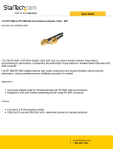
LEDs (2):
Status
Signal
Supplied
Stub
Antenna
SMA Coax
Cable and
Mounting
Bracket for
connecting
Antenna
FIG:fx22_62_gprs_kt
Figure 1: FX22/FX62 GPRS Modem Option Kit
FX22/FX62 Supervisory Controller
GPRS Modem Option Card
Installation Instructions
LP-FXGPRSU-0
Part No. 24-10564-25, Rev. —
Issued October 29, 2010

FX22/FX62 Supervisory Controller GPRS Modem Option Card Installation Instructions2
Installation
Parts Included
This package includes the following items:
• a GPRS modem option card, with pre-attached end
plate
• a Wyless provisioned SIM card, ready for
Pre-installation
• a right-angle GSM/GPRS quad-band SubMiniature
version A (SMA) coax mounted stub antenna
• an antenna mounting bracket
• a 6.56 ft (2 m) SMA coax antenna cable
•this FX22/FX62 Supervisory Controller GPRS
Modem Option Card Installation Instructions (Part
No. 24-10564-25)
Special Tools Needed
The following supplies and tools are required:
• #1 and #2 Phillips screwdrivers: to remove and
refasten covers on the FX22/FX62 Supervisory
Controller, and to install the GPRS modem card.
• Any other tools needed for mounting the antenna
bracket. See Figure 8 for bracket details.
Mounting
Pre-installation
Prior to mounting the GPRS
modem option card in the
FX22/FX62 Supervisory Controller, install the SIM card
into the connector on the underside of the option card.
To install the SIM card, orient the card with its foil
connectors down (writing side up) and its angled corner
out
, and slide the card fully into the connector (see
Figure 2).
Mounting the GPRS Modem Option Card
Mount the GPRS modem option card in the only option
card slot of the FX22/FX62 Supervisory Controller.
1. Remove power from the FX22/FX62 Supervisory
Controller. Wait for all LEDs to turn off.
2. Use a #1 Phillips screwdriver to remove the right
cover first (see Figure 3). Set the two screws aside.
3. Remove the left cover next (see Figure 4). Set the
two screws aside.
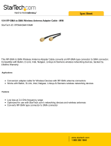
SIM Card
SIM Card
seated fully
in connector
Angled corner out
FIG:fx_sim_crd_gprs
Figure 2: Inserting SIM Card into Underside of
GPRS Modem
!
WARNING: Risk of Electric Shock.
Disconnect power supply before making
electrical connections. Contact with
components carrying hazardous voltage
can cause electric shock and may result
in severe personal injury or death.
IMPORTANT: Be careful to plug any option card
into its connector properly (pins aligned).
Right cover
screws (2)
FIG:fx_22_62_rmv_rt_cvr
Figure 3: Right Cover Removal and Replacement

FX22/FX62 Supervisory Controller GPRS Modem Option Card Installation Instructions 3
4. Use a #2 Phillips screwdriver to remove the
blanking plate from the FX22/FX62 Supervisory
Controller’s option card slot.
5. Carefully insert the pins of the GPRS
modem
option card
into the socket of the option card slot.
Line up the mounting holes on the end plate with
the standoffs on the base board. If the mounting
holes and standoffs do not line up, the connector is
not properly aligned.
6. Press the option card until it is completely seated.
7. Place the two screws through the option card end
plate and into the standoffs on the FX22/FX62
Supervisory Controller base board. Hand tighten
these screws (see Figure 6).
8. Replace the left cover (see Figure 4) and refasten
with the two screws set aside.
Note: Leave the right cover off for the Antenna
Installation. You may wish to leave the right cover off
until you complete Modem Checkout
on page 4, so you
can see the LEDs.
Left cover
screws (2)
Option Card Slot
FIG:fx22_62_rmv_lft_cvr
Figure 4: Left Cover Removal and Replacement
Figure 5: Insert the GPRS Modem Option Card
with Pins Aligned
Insert GPRS
modem option
card into empty
option card slot.
FIG:fx22_62_insrt_optn_crd
Figure 6: GPRS Modem Option Card Inserted,
Screws Tightened
Make sure that the GPRS
option card pins are aligned.
Fully seat the card.
Hand tighten the screws
using a screwdriver.
FIG:fx22_62)gprs_mod_insrtd

FX22/FX62 Supervisory Controller GPRS Modem Option Card Installation Instructions4
Antenna Installation
1. Route the included SMA coax cable through the
appropriate wiring knockout of the FX22/FX62
Supervisory Controller (top, bottom, or back), and
attach the cable to the GPRS modem option card
(see Figure 7).
2. Mount the antenna bracket within reach of the
6.56 ft (2 m) SMA-type coax extension cable.
Figure 8 shows the bracket details and
dimensions.
3. Fasten the end of the SMA coax cable in the
mounting bracket and attach the antenna by finger
tightening the knurled nut.
4. Rotate the antenna to whatever position you need
for mounting clearance and/or best reception.
Note: Some installations may require a different
external antenna.
Note: Any external antenna must be compatible with
the GSM 900/1,800 frequency and the 50-ohm
impedance of the SMA coax connector on the GPRS
modem option.
Operation
LEDs
Two LEDs appear on the end plate of the GPRS
modem option card. On the option card label, these
LEDs appear as STATUS and SIGNAL (Figure 1).
These two LEDs are briefly described as follows:
• STATUS (green) — Flashes various LED patterns
based on the state of the modem. This LED is
directly under control of the modem itself (rather
than the modem driver).
Upon initial power-up, the Status LED pattern is
typically 600 ms On/600 ms Off, and may change
depending on various modem state changes.
• SIGNAL (green) — Indicates the Received Signal
Strength Indicator (RSSI), according to the number
of short (350 ms On) flash patterns. (Analogous to
number of bars on a cell phone.)
For further details on the operation of both LEDs, refer
to the FX GPRS Modem Technical Bulletin
(LIT-12011639).
Modem Checkout
Note: The controller’s right cover must be off to see
the two LEDs on the GPRS modem option card. After
modem checkout, replace the right cover (see
Figure 3).
After mounting the GPRS option card and completing
the antenna installation, power on the FX22/FX62
Supervisory Controller. Following a reboot of the
FX22/FX62 Supervisory Controller, you can configure
the modem by opening a platform connection to the
FX22/FX62.
To verify modem communications, verify that status
properties in the GPRS Modem Configuration
platform view display returned values.
Figure 7: SMA Coax Cable
Routed Through Knockout
FX22/FX62
Route SMA
coax cable
through
wiring
knockout.
6.56 ft
(2 m)
To bracket
and stub
antenna.
Attach SMA
coax cable
to option
card
connector.
FIG:fx22_62_sma_cax_cb
Stub Antenna
Bracket
SMA-type
coax
extension
cable
1.0 (25.4)
.625
(15.9)
.170
(4.32)
1.13
(28.7)
1.25 (31.8)
.251
(6.37)
2.0
(50.8)
.625
(15.9)
.236
(6.0)
Mounting Holes (2)
FIG:fx_SED_ext_brkt_detls_sma
Figure 8: Extension Cable and Antenna
Mounting Bracket Dimensions, in. (mm)

Published in U.S.A. www.johnsoncontrols.com
FX22/FX62 Supervisory Controller GPRS Modem Option Card Installation Instructions 5
Johnson Controls® is a registered trademarks of Johnson Controls, Inc.
All other marks herein are the marks of their respective owners. © 2010 Johnson Controls, Inc.
Building Efficiency
507 E. Michigan Street, Milwaukee, WI 53202
Repair Information
If the GPRS modem option card fails to operate within
its specifications, replace the unit. For a replacement
GPRS option card, contact the nearest
Johnson Controls® representative.
Options and Parts
Standard replacement parts are listed in Table 1.
Approvals
Federal Communications Commission (FCC): The
Siemens® TC63 cellular communications module used
on the LP-FXGPRSU-0 modem option card is FCC
approved, and has an FCC ID of QIPTC63.
COM Slot Assignments
Table 2 lists the COM slot assignments for the
FX22/FX62 Controller with a GPRS modem.
Table 1: Parts for GPRS Modem Option Card
Order Code Description
LP-FXGPRSE-0 Includes a 6.56 ft (2 m) SMA-type
coax extension cable and steel
bracket for wall or panel mounting
of the GPRS Modem antenna.
LP-FXGPRSS-0 Replacement SIM card, provisioned
by Wyless.
LP-KITGPRSA-0 Replacement right-angle
GSM/GPRS quad-band SMA coax
mounted stub antenna.
Table 2: COM Slot Assignments for the FX22/FX62
Controller with a GPRS Modem
FX22/FX62
Only one GPRS card supported
Option Slot
GPRS = COM7, COM8
/