Page is loading ...

FX70 - Wi-Fi Card Installation Instructions 1
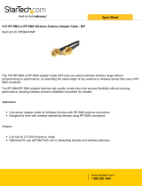
Applications
This document covers the hardware installation of the
802.11b/g Mini Personal Component Interconnect
(PCI) wireless networking card (LP-FX70WIFI-0) for an
FX70 Supervisory controller.
For information on software installation and
configuration required for a supervisory controller, refer
to the FX Workbench User’s Guide (LIT-12011149).
FX70 Wi-Fi Card
The FX70 Wi-Fi card provides Wireless-Fidelity (Wi-Fi)
Local Area Network (LAN) connectivity using the
Institute of Electrical and Electronic Engineers (IEEE)
802.11 b/g standard, seen as Interface 3 in the
Transmission Control Protocol/Internet Protocol (TCP/
IP) Configuration of the FX70 Supervisory Controller.
You install the FX70 Wi-Fi card in the controller’s Mini
PCI slot, using a short micro-coax cable that allows the
included stub antenna to be mounted on the controller.
A 6.6 ft. (2 m) coax extension cable and bracket is also
included.
North American Emissions Compliance
United States
Canada
Installation
We recommend that you remove the controller from
any mounting, and use a flat, well-lit, anti-static (ESD
safe) surface to install this adapter card in the
controller.
Before installation, be sure to carefully attach of the
micro-coax cable to the Mini-PCI Wi-Fi card.
Parts Included
This package includes the following items:
• a Mini PCI 802.11b/g network adapter card
• a short micro-coax cable with a U.FL connector
end and an RP-SMA coax end (for the antenna)
• a tilt-and-swivel, RP-SMA 2.4 GHz stub antenna
• a 6.6 ft (2 m) RP-SMA-type coax extension cabl
e
an
d metal bracket for relocating the antenna
Figure 1: FX70-Wi-Fi (Card, Micro-Coax Cable,
and Antenna)
This equipment has been tested and found to
comply with the limits for a Class A digital device
pursuant to Part 15 of the FCC Rules. These limits
are designed to provide reasonable protection
against harmful interference when this equipment is
operated in a commercial environment. This
equipment generates, uses, and can radiate radio
frequency energy and, if not installed and used in
accordance with the instruction manual, may cause
harmful interference to radio communications.
Operation of this equipment in a residential area is
likely to cause harmful interference, in which case
the user will be required to correct the interference
at his/her own expense.
This Class (A) digital apparatus meets all the
requirements of the Canadian Interference Causing
Equipment Regulations.
Cet appareil numérique de la Classe (A) respecte
toutes les exigences du Règlement sur le matériel
brouilleur du Canada.
FX70 - Wi-Fi Card
Installation Instructions
Part No. 24-10174-107, Rev. A
Issued April 9, 2014
Supersedes October 31, 2011

FX70 - Wi-Fi Card Installation Instructions2
• a 6.56 ft (2 m) SMA coax antenna cable
• an FCC/IC listing label, to apply on the controller
•this FX70 Wi-Fi Card Installation Instructions (Part
No. 24-10174-107)
Special Tools Needed
The following supplies and tools are required:
• 1/4 inch (6 mm) nut driver (NiMH battery bracket).
• #2 Phillips screwdriver (for shield and card screws)
• anti-static mat or equivalent ESD safe work surface
• long-nose pliers (to grip and remove antenna
connector cutout in plastic cover)
• appropriate tools and screws for mounting the
antenna bracket, if used
Mounting
Pre-installation
Before you install the FX70 Wi-Fi card, you must attach
the micro-coax cable to the tiny Main J1 coax port on the
card. Use Hirose U.FL coaxial connector to attach this
cable (Figure 2).
IMPORTANT: Be careful to attach this micro-coax
cable correctly. Keep the female (U.FL) end square to
the card as you press the cable onto the male port.
Insertion at an angle may damage the cable or the
card.
Keep the connector square to the card. You should feel
a small click while squeezing the connector onto the
card’s Main J1 antenna port (
Figure 3
).
!
WARNING: Risk of Electric Shock.
Disconnect power supply before making
electrical connections. Contact with
components carrying hazardous voltage
can cause electric shock and may result
in severe personal injury or death.
AVERTISSEMENT: Risque de
décharge électrique. Débrancher
l'alimentation avant de réaliser tout
branchement électrique. Tout contact
avec des composants conducteurs de
tensions dangereuses risque d'entraîner
une décharge électrique et de provoquer
des blessures graves, voire mortelles.
Figure 2: Mini-PCI Wi-Fi Card and Micro-Coax
Cable
Figure 3: Press the U.FL Coaxial Connector
Together

FX70 - Wi-Fi Card Installation Instructions 3
The click means the cable is attached. Carefully swivel
the cable around as needed during the rest of the
installation.
Note: Avoid any strain on this cable while continuing
with the installation of this card in the controller.
Mounting the FX70 Wi-Fi Card
Before you mount the Wi-Fi card, you must first
complete the installation of the micro-coax cable. See
Pre-installation
.
Installation also involves the removal and subsequent
replacement of any installed card in Slot 1 (to remove
and replace the metal shield).
Note: Any card in Slot 2 can remain in place.
1. Back up the FX70 controller's configuration to your
computer using FX Workbench.
2. Remove power from the FX70.
Note: If a 12 V sealed lead acid backup battery is
attached, disconnect the battery from the
controller.
Wait for all LED activity to stop. This should take
several seconds. All LEDs on the FX70 should be
off.
3. Remove the controller from any mounting and
place it on a flat, well-lit surface.
4. Remove the controller’s cover. To remove the
controller’s cover, press in the four tabs on both
ends of the unit, and lift the cover off.
Note: An LED ribbon cable connects the cover to
the main board. Be careful when lifting the cover
off.
5. Unplug the LED ribbon cable from the connector
on the controller (
Figure 5
). Move the cover
assembly aside.
6. Remove the NiMH battery and its metal bracket.
Note: You can install the without removing the
battery/bracket from the shield. However, removing
the battery/bracket makes it easier to move the
shield around later, when fastening the antenna
coax connector in the shield hole.
IMPORTANT: Turn off power to the controller when
you install or remove cards or a Mini-PCI card.
Otherwise, damage occurs. Also, when you install a
card, you must be very careful to plug the card into
its connector properly (pins aligned).
Figure 4: Cable Attached and Adapter Card
Ready to Install
Figure 5: LED Ribbon Cable Connector on
Controller
Figure 6: Remove Two Nuts and Battery Pack,
Bracket

FX70 - Wi-Fi Card Installation Instructions4
Use a 1/4 inch (6 mm) nutdriver to unfasten the two
keps nuts that secure the bracket (
Figure 6
). Retain
the nuts. Lift the battery and bracket off, keeping
the two items together (
Figure 7
).
7. Unplug the NiMH battery from the main board
(
Figure 7
).
Set the battery pack and bracket aside, keeping
them together.
8. If necessary, use a #2 Phillips screwdriver to
remove the card in Slot 1. Otherwise, unfasten the
two screws that hold the Slot 1 blanking plate.
Remove the remaining shield screws (
Figure 8
),
and retain all screws.
9. Lift the shield away from the unit (
Figure 9
).
Note the Mini-PCI socket on the controller board
and the two antenna connector holes on the shield.
Note: If you want to add a new card in Slot 2,
install the card now (before replacing shield). Be
sure to correctly align the card's header pins into
the connector socket.
10. Insert the Wi-Fi adapter card into the socket, at an
angle of around 25 degrees (
Figure 10
).
The edge connectors of the card should be fully
seated in the socket.
Figure 7: Unplug NiMH Battery on Controller Board
Figure 8: Remove Slot 1 Item, Unfasten Shield
Screws
Figure 9: Shield Lifted Away from Controller
Figure 10: Insert Adapter Card in Socket at
Slight Angle

FX70 - Wi-Fi Card Installation Instructions 5
11. Press down on the adapter card while pressing in
the socket, until the socket side clamps snap in
place on the card (
Figure 11
).
Lock the socket clamp on each side of the card in
place, with the edge connectors of the card seated
firmly in the socket.
12. With the card installed, remove the nut and lock
washer from the coax connector, and insert the
threaded end through either of the two holes on the
underside of the shield.
Install the lock washer and thread the nut onto the
coax connector (
Figure 12
). Tighten the nut (be
careful not to twist or pull the micro-coax cable).
Figure 13
shows the shield ready to reposition back
onto the controller, with the Wi-Fi card installed,
and the antenna coax connector mounted in the
shield hole.
Be careful not to pinch the micro-coax cable when
you reposition the shield back onto the controller.
13. Position the shield back into place and secure with
the screws previously removed.
If necessary, replace any card removed from Slot
1, refastening the two mounting screws. Otherwise,
refasten the screws holding the Slot 1 blanking
plate (
Figure 14
).
Note: When you install a card, be sure to align the
header pins of the card correctly into the connector
socket.
Figure 11: Press Down and in Until Socket
Clamps Lock
Figure 12: Coax Connector through Shield Hole
Figure 13: Card Installed, Shield Ready to
Reposition
Figure 14: Reposition Shield, Slot 1 Item,
Refasten Screws

FX70 - Wi-Fi Card Installation Instructions6
14. Replace the NiMH battery pack and mounting
bracket onto the shield and refasten the two keps
nuts using a 1/4 inch (6 mm) nutdriver (
Figure 15
).
15. Plug the connector plug of the battery into the
NiMH battery connector on the controller
(
Figure 16
).
Note: The red wire goes towards the outside
edge. You cannot plug the battery in reversed.
16. Before you replace the plastic cover, remove the
antenna knockout. To remove the antenna
knockout, first grip the knockout with a pair of long
nose pliers (
Figure 17
).
Gripping tightly, twist the pliers jaws to break the
cutout free from the cover (
Figure 18
).
Clean up any jagged edges of the cutout, by
burnishing with the rounded edges of the pliers.
Figure 15: Refasten NiMH Battery and Bracket
Nuts
Figure 16: Replug NiMH Battery Cable into
Controller
Figure 17: Grip Antenna Knockout on Cover with
Pliers
Figure 18: Remove Cover Antenna Knockout

FX70 - Wi-Fi Card Installation Instructions 7
17. Reconnect the LED ribbon cable from the cover to
the connector on the controller (
Figure 19
).
18. Apply the included FCC/IC listing label onto an
available area of the controller’s metal shield.
19. Replace the cover onto controller, orienting the
antenna knockout over the coax connector.
Note: Make sure that the LED ribbon cable is
connected and not outside the base.
20. Press down on both ends of cover to make sure
end tabs (two on each side) are snapped in place.
21. If necessary, remount the controller.
22. If accessory modules were unplugged, plug them
back into the controller as before, and secure.
23. If you disconnected an external, 12 V sealed
lead-acid battery, reconnect the battery back to the
controller.
Antenna Installation
A 2.4 GHz stub antenna with tilt-and-swivel RP-SMA
female coax connector is provided for use with the
Wi-Fi adapter in the FX70 controller. To attach the
antenna, insert it into the RP-SMA coax jack on the
controller, and finger-tighten the knurled nut
(
Figure 22
).
Figure 19: Reconnect LED Ribbon Cable in
Controller
Figure 20: Replace Cover Back on Controller
Figure 21: Cover Replaced on Controller
Figure 22: RP-SMA Stub Antenna on
Controller

Published in U.S.A. www.johnsoncontrols.com
FX70 - Wi-Fi Card Installation Instructions8
Johnson Controls® is a registered trademark of Johnson Controls, Inc.
All other marks herein are the marks of their respective owners. © 2014 Johnson Controls, Inc.
Building Efficiency
507 E. Michigan Street, Milwaukee, WI 53202
Rotate in whatever position is needed for mounting
clearance and/or best reception.
If needed, use the included antenna extension cable.
Typically, this cable is required when the controller is
installed inside a metal enclosure.
Note: The antenna cannot be any closer than 10
inches (254 mm) to any other antenna (for example, on
another wireless card also installed in the controller). In
this case, use the included antenna extension cable kit
to relocate the antenna to maintain this minimum
distance.
Antenna Extension Cable
To locate the included stub antenna off the FX70
controller, install the included cable extension kit.
Included is a 6.6 ft (2 m) RP-SMA-type coax extension
cable and a steel bracket for wall or panel mounting.
See
Figure 23
for bracket details and dimensions.
Repair Information
If the FX70 Wi-Fi card fails to operate within its
specifications, replace the unit. For a replacement
card, contact the nearest Johnson Controls®
representative.
Replacement Parts
Standard replacement parts are listed in Table 1.
Figure 23: Extension Cable Bracket Details
Table 1: Parts for FX70 Wi-Fi Card
Order Code Description
LP-FXSEDEXT-0 Replacement 6.56 ft (2 m) RP-SMA
type coax extension cable, and
mounting bracket. See Antenna
Extension Cable.
LP-KITSEDAT-0 Replacement adjustable-angle 2.4
GHz RP-SMA coax-mounted stub
antenna.
/