Page is loading ...

ACS 600 Frequency Converters
equipped with Standard Application Program 5.x
ACS 600 Start-up Guide
This manual includes:
• ACS 600 initialisation using the Control
Panel
• First start
• Rotation direction check
• Start through a digital input
• Speed control using the Control Panel
and through an analogue input

3BFE 64049224 R0125
EN
EFFECTIVE: 26.08.1998
SUPERSEDES: None
1998 ABB Industry Oy. All Rights Reserved.
This Guide describes the basic start-up procedure of the
ACS 600 frequency converter equipped with the Standard
Application Program 5.x.
See the
for more information on
• the use of the Control Panel,
• the control connections,
• the Parameters,
• the fault tracing.

Start-up Guide
Standard Application Program 1
START-UP PROCEDURE
1 – SAFETY
The start-up procedure must only be carried out by a qualified electrician.
The safety instructions must be followed during the start-up procedure. See the
appropriate hardware manual for the safety instructions.
The ACx 600 must not be powered up more than five times in ten minutes to avoid
charging resistor overheating (no limitation for ACS 600 MultiDrive and ACx 607
units -0760-3, -0930-5, -0900-6 or above).
Check the installation before the start-up procedure. See the installation checklist from the
appropriate hardware/installation manual.
Check that starting the motor does not cause any danger.
It is recommended having the driven equipment disengaged when first start is performed if
there is the risk of damage to the driven equipment in case of incorrect rotation direction of
the motor.
2 – POWER-UP
Apply mains power. The Control Panel first enters the
panel identification data ...
... then the Identification Display of the drive ...
...and after a few seconds the Control Panel automatically
enters the Actual Signal Display.
Drive set-up can be started.
CDP312 PANEL Vx.xx
.......
ACS 600 xx kW
ID NUMBER 1
1 -> 0.0 rpm O
FREQ 0.00 Hz
CURRENT 0.00 A
POWER 0.00 %

Start-up Guide
2
Standard Application Program
3 – START-UP DATA ENTERING (Parameter Group 99)
Select the language. The general parameter setting
procedure is given below.
The general parameter setting procedure:
• Press
PAR
to select parameter mode.
• Press or to scroll Parameter Groups (10 to 99).
• Press or to scroll parameters within the
Parameter Group.
• Select a new value by
ENTER
(brackets appear around
the parameter value) and or . (Fast change by
or .)
• Press
ENTER
to accept the new value (brackets
disappear).
Select the Application Macro. The general parameter
setting procedure is given above.
The default value FACTORY is suitable in most cases. A detailed
description of the Application Macros is included in
Firmware Manual.
Select the motor control mode. The general parameter
setting procedure is given above.
DTC is suitable in most cases. The SCALAR control mode is
recommended
• for multimotor drives when the number of motors connected to the
ACS 600 is variable.
• when the nominal current of the motor is less than 1/6 of the nominal
current of the inverter.
• when the inverter is used for test purposes with no motor connected.
START-UP PROCEDURE
1 -> 0.0 rpm O
99 START-UP DATA
01 LANGUAGE
ENGLISH
1 -> 0.0 rpm O
99 START-UP DATA
01 LANGUAGE
[ENGLISH]
1 -> 0.0 rpm O
99 START-UP DATA
02 APPLICATION MACRO
[ ]
1 -> 0.0 rpm O
99 START-UP DATA
04 MOTOR CTRL MODE
[DTC]

Start-up Guide
Standard Application Program 3
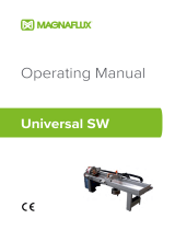
Enter the motor data from the motor nameplate.
Note:
Set the motor data exactly the same as on the motor
nameplate. For example, if the motor nominal speed is
1440 rpm on the nameplate, setting the value of Parameter
99.08 MOTOR NOM SPEED to 1500 rpm results in wrong
operation of the drive.
Nominal voltage. The general parameter setting procedure
is given on Page 2.
Allowed range: 1/2 ·
U
N
... 2 ·
U
N
of ACS 600. (
U
N
refers to the highest
voltage in each of the nominal voltage ranges: 415 VAC for 400 VAC
units, 500 VAC for 500 VAC units and 690 VAC for 600 VAC units.)
Nominal current. The general parameter setting procedure
is given on Page 2.
Allowed range: 1/6 ·
I
2hd
... 2 ·
I
2hd
of ACS 600
Nominal frequency. The general parameter setting
procedure is given on Page 2.
Range: 8 ... 300 Hz
Nominal speed. The general parameter setting procedure
is given on Page 2.
Range: 1 ... 18000 rpm
START-UP PROCEDURE
M2AA 200 MLA 4
1475
1475
1470
1470
1475
1770
32.5
56
34
59
54
59
0.83
0.83
0.83
0.83
0.83
0.83
3GAA 202 001 - ADA
180
IEC 34-1
6210/C36312/C3
Cat. no
35
30
30
30
30
30
50
50
50
50
50
60
690 Y
400 D
660 Y
380 D
415 D
440 D
V
Hz kW
r/min A
cos
IA/IN
t
E/s
Ins.cl. F
IP 55
No
IEC 200 M/L 55
3
motor
ABB Motors
380 V
Mains
Voltage
1 -> 0.0 rpm O
99 START-UP DATA
05 MOTOR NOM VOLTAGE
[ ]
1 -> 0.0 rpm O
99 START-UP DATA
06 MOTOR NOM CURRENT
[ ]
1 -> 0.0 rpm O
99 START-UP DATA
07 MOTOR NOM FREQ
[ ]
1 -> 0.0 rpm O
99 START-UP DATA
08 MOTOR NOM SPEED
[ ]

Start-up Guide
4
Standard Application Program
Nominal power. The general parameter setting procedure is
given on Page 2.
Range: 0... 9000 kW
When the motor data has been entered a warning appears.
It indicates that the motor parameters have been set, and
the ACS 600 is ready to start the motor identification
(ID magnetisation or ID Run).
Select the motor identification. The general parameter
setting procedure is given on Page 2.
The default value NO is suitable for most applications. It is applied in this
basic start-up procedure.
The ID Run (STANDARD or REDUCED) should be selected instead if:
• Operation point is near zero speed.
• Operation at torque range above the motor nominal torque within wide
speed range and without any pulse encoder (i.e. without any
measured speed feedback) is required.
See the
Firmware Manual
for the ID Run procedure.
4 – IDENTIFICATION MAGNETISATION
with Motor ID Run selection NO
Press the
LOC/REM
key to change to local control (L
shown on the first row).
Press the to start the magnetisation. The motor is
magnetised at zero speed for 20 to 60 s. Two warnings are
displayed:
• The upper warning is displayed while the magnetisation
is on.
• The lower warning is displayed after the magnetisation is
completed.
START-UP PROCEDURE
1 -> 0.0 rpm O
99 START-UP DATA
09 MOTOR NOM POWER
[ ]
1 -> 0.0 rpm O
** WARNING **
ID MAGN REQ
1 -> 0.0 rpm O
99 START-UP DATA
10 MOTOR ID RUN
[NO]
1 L-> 0.0 rpm I
** WARNING **
ID MAGN
1 L-> 0.0 rpm O
** WARNING **
ID DONE

Start-up Guide
Standard Application Program 5
5 – ROTATION DIRECTION OF THE MOTOR
Check the rotation direction of the motor.
• Press
ACT
to get the status row visible.
• Increase the speed reference from zero to a small value
by pressing
REF
and then or ( or ).
• Press (Start) to start the motor.
• Check that the motor is running in the desired direction.
• Stop the motor by pressing .
To change the rotation direction of the motor:
• Disconnect mains power from the ACx 600, and wait 5 minutes for the
intermediate circuit capacitors to discharge. Measure the voltage
between each input terminal (U1, V1 and W1) and earth with a
multimeter to ensure that the frequency converter is discharged.
• Exchange the position of two motor cable phase conductors at the
motor terminals or at the motor connection box.
• Verify your work by applying mains power and repeating the check as
described above.
6 – SPEED LIMITS AND ACCELERATION/DECELERATION TIMES
Set the minimum speed. The general parameter setting
procedure is given on Page 2.
Set the maximum speed. The general parameter setting
procedure is given on Page 2.
Set the acceleration time 1. The general parameter setting
procedure is given on Page 2.
Note:
Check also acceleration time 2, if two acceleration
times will be used in the application.
Set the deceleration time 1. The general parameter setting
procedure is given on Page 2.
Note:
Set also deceleration time 2, if two deceleration
times will be used in the application.
START-UP PROCEDURE
1 L->[xxx] rpm I
FREQ xxx Hz
CURRENT xx A
POWER xx %
forward
direction
reverse
direction
1 L-> 0.0 rpm O
20 LIMITS
01 MINIMUM SPEED
[ ]
1 L-> 0.0 rpm O
20 LIMITS
02 MAXIMUM SPEED
[ ]
1 L-> 0.0 rpm O
22 ACCEL/DECEL
02 ACCELER TIME 1
[ ]
1 L-> 0.0 rpm O
22 ACCEL/DECEL
03 DECELER TIME 1
[ ]

Start-up Guide
6
Standard Application Program
7 – STARTING THE DRIVE THROUGH THE I/O INTERFACE
As default the external start/stop signal is read from the
digital input DI1, and the external speed reference from the
analogue input AI1.
Starting through a digital input:
• Press the
LOC/REM
key to change to external control
(no L visible on the first row of the panel display).
• Switch on digital input DI1.
Drive starts. The motor is accelerated to a speed
determined by the voltage level of analogue input AI1.
Valid if the factory macro is
selected. See Parameter
99.02 APPLICATION MACRO.
8 – STOPPING THE MOTOR
Stopping when in local control: Press .
Stopping when in external control: Switch off digital input
DI1.
Valid if the factory macro is
selected. See Parameter
99.02 APPLICATION MACRO.
Press the
LOC/REM
key to change between local and
external control.
START-UP PROCEDURE


ABB Industry Oy
Drives
P.O.Box 184
FIN-00381 HELSINKI
FINLAND
Telephone: +358-10 22 2000
Telefax: +358-10-22 22681
3BFE 64049224 R0125
EFFECTIVE: 26.08.1998 EN
/