Page is loading ...

Operation Manual
ABB Turbocharging
ABB Turbo Systems Ltd
CH 5401 Baden
Type TPR56-F67 HT548296
n
Mmax
721 t
Mmax
680
n
Bmax
688 t
Bmax
650
1/s °C
00360 - 50 50
Year 2019
made in Switzerland
Application according to
the Operation Manual
kg
HZTL2490 English
TPR56-F67
Original Operation Manual

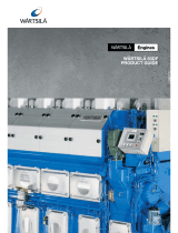
Operating condition and replacement intervals
The operational limits for the turbocharger nBmax, tBmax, nMmax, tMmax, inspection- and replacement intervals for the compon-
ents concerned on the rating plate are valid for the operational mode and compressor inlet condition, which has been agreed upon
between the engine builder and ABB.
Note: Replacement intervals of components depends on the load profi le, turbine inlet temperature, suction air temperature and
turbocharger speed. In case the operation conditions differs signifi cantly from what is considered to be normal for the cur-
rent application, it is recommended to contact ABB for a re-calculation of replacement intervals. Frequent load alterations,
high temperatures and high speed lower the life of components.
Unless otherwise agreed, the application limits nMmax, tMmax are valid for the test operation for a limited time.

Operation Manual / TPR56-F + TPR61-F
Table of contents
© Copyright 2018 . All rights reserved. HZTL2490_EN Revision D May 2018
Operation Manual
1 Preliminary remarks................................................................................................. 3
1.1 Purpose of this manual .................................................................................................. 3
1.2 Layout and function........................................................................................................ 4
1.3 Intended use of the turbocharger .............................................................................. 6
1.4 Storage of new turbochargers and spare parts ....................................................... 7
1.5 Essential information..................................................................................................... 9
1.6 Symbols and definitions .............................................................................................. 11
1.7 Turbocharger rating plate ........................................................................................... 12
1.8 Contact information..................................................................................................... 13
2 Safety...................................................................................................................... 14
2.1 Introduction ................................................................................................................... 14
2.2 CE conformity ................................................................................................................ 14
2.3 Definition of mandatory signs ................................................................................... 15
2.4 Definition of Safety instructions ............................................................................... 15
2.5 Warning plates on the turbocharger......................................................................... 16
2.6 Safe operation and maintenance............................................................................... 17
2.7 Hazards during operation and maintenance........................................................... 20
2.8 Periodic checking of the pressure vessel ................................................................. 25
2.9 Lifting loads ................................................................................................................... 26
3 Start-up / commissioning .................................................................................... 27
3.1 Oil supply ........................................................................................................................ 27
3.2 Inspection work............................................................................................................ 30
3.3 Commissioning after taking out of operation........................................................ 32
4 Operation ................................................................................................................ 33
4.1 Noise emissions ............................................................................................................ 33
4.2 Servicing work ............................................................................................................... 35
4.3 Replacement intervals for turbocharger components.......................................... 37
4.4 Speed measurement .................................................................................................... 39
4.5 Stopping the engine ..................................................................................................... 42
5 Maintenance .......................................................................................................... 43
5.1 Foreword to Maintenance ........................................................................................... 43
5.2 Cleaning the filter silencer.......................................................................................... 44
6 Troubleshooting.................................................................................................... 46
6.1 Malfunctions when starting....................................................................................... 46
6.2 Surging of the turbocharger....................................................................................... 47

Operation Manual / TPR56-F + TPR61-F
Table of contents
© Copyright 2018 . All rights reserved. HZTL2490_EN Revision D May 2018
6.3 Malfunctions during operation ................................................................................. 48
6.4 Malfunctions when stopping ..................................................................................... 50
6.5 Speed measurement system ...................................................................................... 51
7 Removal and installation...................................................................................... 52
7.1 Turbocharger weights.................................................................................................. 52
7.2 Removing the turbocharger........................................................................................ 52
7.3 Installing the turbocharger ........................................................................................ 54
8 Disassembly and assembly .................................................................................. 55
8.1 Introduction ................................................................................................................... 55
8.2 Module weights ............................................................................................................. 57
8.3 Removing and installing the air suction branch / filter silencer ......................... 58
8.4 Axial clearance .............................................................................................................. 60
8.5 Removing cartridge group .......................................................................................... 61
8.6 Dismantling and installing the turbine diffuser and nozzle ring ......................... 65
8.7 Installing cartridge group............................................................................................ 67
8.8 Table of tightening torques........................................................................................ 70
9 Mothballing the turbocharger .............................................................................. 72
9.1 Taking the engine out of operation for up to 12months...................................... 72
9.2 Taking the engine out of operation for more than 12months ............................ 74
10 Disposing of turbocharger components............................................................ 75
11 Spare parts............................................................................................................. 76
11.1 Ordering spare parts .................................................................................................... 76
11.2 View of turbocharger with part numbers ................................................................ 78

Operation Manual / TPR56-F + TPR61-F
1 Preliminary remarks / 1.1 Purpose of this manual
© Copyright 2018 . All rights reserved. HZTL2490_EN Revision D May 2018
1 Preliminary remarks
1.1 Purpose of this manual
This Operation Manual belongs to the turbocharger with the identical
serial number (01), see the cover sheet of the Operation Manual and the
turbocharger rating plate.
Operation Manual
The Operation Manual explains the turbocharger and contains instruc-
tions for safe operation.
The Operation Manual is a complement to and expansion of existing na-
tional regulations for occupational safety, accident prevention and envir-
onmental protection.
Target group
The Operation Manual is aimed at engineers and trained mechanics re-
sponsible for the proper operation of the engine and for the turbochar-
ger connected to it.
Availability of the Operation Manual
The Operation Manual must be available where the turbocharger is used.
All persons operating or working on the turbocharger must have read
and fully understood the Operation Manual.
Page 3 / 79

Operation Manual / TPR56-F + TPR61-F
1 Preliminary remarks / 1.2 Layout and function
© Copyright 2018 . All rights reserved. HZTL2490_EN Revision D May 2018
1.2 Layout and function
01 Suction branch / filter silencer 06 Gas inlet casing
02 Compressor wheel 07 Nozzle ring
03 Diffuser 08 Turbine
04 Bearing bush 09 Bearing casing
05 Gas outlet casing 10 Compressor casing
Page 4 / 79

Operation Manual / TPR56-F + TPR61-F
1 Preliminary remarks / 1.2 Layout and function
© Copyright 2018 . All rights reserved. HZTL2490_EN Revision D May 2018
Mode of operation
The turbocharger is a turbomachine consisting of two main compon-
ents, a turbine and a compressor. These components are mounted on a
common shaft and form the rotor.
In the turbocharger shown in the illustration, the exhaust gas flows
through the gas inlet casing(06) and the nozzle ring(07) and arrives at
the turbine(08). The turbine utilises the energy contained in the exhaust
gas to drive the rotor. The exhaust gases then escape into the open air
through the gas outlet casing(05) and the exhaust gas pipe connected
to it.
The rotor runs in two radial plain bearings, which are located between
the compressor and the turbine in the bearing bush(04). The axial bear-
ing is also a plain bearing. The plain bearings are connected to a central
lubricating oil duct which is normally supplied by the lubricating oil cir-
cuit of the engine. The oil outlet is situated at the lowest point of the
bearing casing(09).
The compressor wheel(02) connected to the shaft draws in fresh air
through the filter silencer(01) or the air suction branch. The air is com-
pressed in the compressor and the downstream diffuser(03) and then
led to the charge air cooler via the compressor casing(10).
Page 5 / 79

Operation Manual / TPR56-F + TPR61-F
1 Preliminary remarks / 1.3 Intended use of the turbocharger
© Copyright 2018 . All rights reserved. HZTL2490_EN Revision D May 2018
1.3 Intended use of the turbocharger
NOTICE
The turbochargers supplied by ABB have been developed for use on in-
ternal combustion engines to generate the volume of air and the char-
ging pressure required to operate the engine.
The enginebuilder has provided ABB Turbo Systems with information
regarding the intended purpose of use of the engine, from which the
specific operating limits shown on the turbocharger rating plate (such
as speeds, temperatures and replacement intervals) have been determ-
ined.
Any other use is considered to be a special application, which must first
be clarified with ABB. The manufacturer accepts no liability for any
other type of use. If the equipment is used for any other purpose, ABB
reserves the right to reject all warranty claims.
State of the art
This turbocharger was built according to state-of-the-art technology
and is operationally safe according to recognised safety regulations.
WARNING
Improper operation and maintenance of the turbocharger can result in
danger to life and limb of the user or third parties. In addition, im-
proper use may cause damage to the machine.
u The machine may be operated only by trained personnel.
Use of the turbocharger as intended also includes observance of the in-
stallation / fitting, disassembly / removal, operating, maintenance / ser-
vicing and repair conditions specified by the manufacturer. Disposal reg-
ulations set down by local authorities must be observed.
Perfect condition
The turbocharger may be installed only when in technically perfect condi-
tion while observing the instructions given in the engine builder's
manual. It may be used only for the intended purpose and operated in
compliance with the operation manual.
u Malfunctions which could affect safety must be eliminated immedi-
ately.
The manufacturer accepts no liability for any damage resulting from un-
authorised alterations to the turbocharger.
Page 6 / 79

Operation Manual / TPR56-F + TPR61-F
1 Preliminary remarks / 1.4 Storage of new turbochargers and spare
parts
© Copyright 2018 . All rights reserved. HZTL2490_EN Revision D May 2018
1.4 Storage of new turbochargers and spare parts
Storage of new turbochargers and spare parts up to 6 months
New turbochargers and spare parts can be stored in sealed packaging
without additional mothballing measures for up to 6months from the
date of delivery (marked by the VCI label on the package).
Fig.1: Volatile Corrosion Inhibitor (VCI)
Only dry rooms in which the relative humidity is between 40…70 % and
no condensation can form are suitable for storage.
Storage of new turbochargers and spare parts for more than 6
months
WARNING
Protection of health when handling VCIs
VCI products are not hazardous in the sense of the Hazardous Sub-
stances Ordinance. Nevertheless, the following points are to be ob-
served when handling VCIs:
u Observe specifications in the safety data sheet
u Ensure good room ventilation.
u Do not eat, drink or keep food at the workplace while working with
VCIs.
u Clean hands and face after working with VCIs.
u For further information refer to www.branopac.com.
Wear safety gloves to protect against mechanical hazards.
The following mothballing measures are required every 6months:
u Open the package.
u Remove the VCI corrosion protection emitter from the package and
replace it with a new, identical VCI corrosion protection emitter. New
VCI corrosion protection emitters can be obtained at www.brano-
pac.com.
u Dispose of the old VCI corrosion protection emitter in an environ-
mentally compatible manner, professionally and in accordance with
local regulations.
u Seal the package. The better the external seal is designed, the more
permanent the protection.
Page 7 / 79

Operation Manual / TPR56-F + TPR61-F
1 Preliminary remarks / 1.4 Storage of new turbochargers and spare
parts
© Copyright 2018 . All rights reserved. HZTL2490_EN Revision D May 2018
Long-term storage of replacement turbochargers or spare parts
The turbochargers or cartridge groups will be prepared for prolonged
storage by ABB Turbo Systems on request. The package is equipped
with a hygrometer (see illustration).
Fig.2: Package with hygrometer
The following measures are required every 6months:
u Check the hygrometer(02) in the sight-glass. There is an opening(01)
in the wooden crate which allows this check to be carried out. When
the display field has changed colour at the 70% level, the maximum
permissible humidity has been exceeded. In this case the turbochar-
ger or cartridge group must be inspected by an ABB Turbocharging
Service Station and repacked.
u Inspect the package for damage. If the package is damaged, the tur-
bocharger or cartridge group must be inspected by an ABB Tur-
bocharging Service Station and repacked.
After every 3 years the following work steps must be performed by an
ABB Turbocharging Service Station:
¡ Inspect the components
¡ Replace the desiccant agent
¡ Repackage the components.
If the 70% display field of the hygrometer(02) has not changed colour
and the package is undamaged, the replacement turbocharger or re-
placement cartridge group can be placed into operation without any
prior testing by an ABB Turbocharging Service Station.
Unpacking replacement turbochargers or spare parts
The corrosion protection effect ends after the material is unpacked from
the VCI package.
To avoid the formation of condensation, the surroundings and the con-
tent of the package must have the same temperature during unpacking.
Page 8 / 79

Operation Manual / TPR56-F + TPR61-F
1 Preliminary remarks / 1.5 Essential information
© Copyright 2018 . All rights reserved. HZTL2490_EN Revision D May 2018
1.5 Essential information
Organisational measures
In addition to the Operation Manual, the general statutory regulations
for the prevention of accidents and for environmental protection in the
country of use must also be observed.
This also applies to the provision and wearing of personal protective
equipment.
NOTICE
The manner in which personnel work on and with the turbocharger with
regard to safety and risks is to be checked on a regular basis in accord-
ance with the Operation Manual.
u The turbocharger must be shut down immediately in the event of
modifications affecting safety or of corresponding operating beha-
viour by stopping the engine. The fault should be reported to the per-
son or department responsible.
NOTICE
Any modifications, additions or conversions made to the turbocharger,
which could impair safety, require the prior approval of ABB Turbo Sys-
tems.
Page 9 / 79

Operation Manual / TPR56-F + TPR61-F
1 Preliminary remarks / 1.5 Essential information
© Copyright 2018 . All rights reserved. HZTL2490_EN Revision D May 2018
Original parts and safety
Original parts and accessories are specially designed for the turbochar-
ger supplied by ABB.
WARNING
Use original parts
Operation of the turbocharger with non-original parts can impair the
safety of the turbocharger and can cause serious damage to property
and injury to personnel.
u Only use original parts from ABB.
ABB accepts no liability for any damage resulting from the use of non-
original parts and corresponding accessories.
Competence of personnel
The turbocharger must only be operated and serviced by trained and au-
thorised personnel. Basic mechanical training is a prerequisite.
Design variants
This document is valid for different design variants of turbochargers.
There may be sections and descriptions of components that are not rel-
evant for a specific turbocharger variant.
ABB Turbocharging Service Stations will be happy to provide information
on questions regarding a design variant (see Contact information at
www.abb.com/turbocharging).
Accuracy of illustrations
The illustrations in this document are general in nature and intended for
ease of understanding. Differences in detail are therefore possible.
Registered trademarks
Registered trademarks of external companies are used in this document.
The trademarks are marked with ®.
Page 10 / 79

Operation Manual / TPR56-F + TPR61-F
1 Preliminary remarks / 1.6 Symbols and definitions
© Copyright 2018 . All rights reserved. HZTL2490_EN Revision D May 2018
1.6 Symbols and definitions
The following symbols are used in the documents:
w Prerequisite
u Work step
¡ Enumeration, first level
- Enumeration, second level
→ Refers to a page number
Definition of notes
NOTICE
Note
A note provides suggestions which facilitate the work on the product.
Definition of mandatory signs
Mandatory signs show the protective equipment to be worn for a task.
The mandatory signs are described in chapter Safety and must be com-
plied with.
Definition of caution / warning
The caution and warning signs are described in the chapter Safety.
ABB Turbo Systems
In this document, ABB Turbo Systems Ltd is abbreviated to ABB Turbo
Systems.
Official ABB Turbo Systems Service Stations
In this document, official service stations are referred to as ABB Tur-
bocharging Service Stations. They are inspected and certified regularly
by ABB Turbo Systems. See also chapter Contact information →13.
Page 11 / 79

Operation Manual / TPR56-F + TPR61-F
1 Preliminary remarks / 1.7 Turbocharger rating plate
© Copyright 2018 . All rights reserved. HZTL2490_EN Revision D May 2018
1.7 Turbocharger rating plate
Operating limits
01 Turbocharger operating limits at engine overload (110%).
Only when operating in the test rig unless otherwise agreed with the
enginebuilder.
02 Turbocharger operating limits during operation
Recommended replace-
ment intervals for tur-
bocharger components
03 Replacement interval for plain bearings in 1000 h
04 Replacement interval for compressor in 1000 h
05 Replacement interval for turbine in 1000 h
Further information
06 Part number for customer
07 Designation of special design
08 Turbocharger weight in kg
09 Turbocharger type
10 Serial number
11 Year of turbocharger construction
12 Manufacturing plant
Page 12 / 79

Operation Manual / TPR56-F + TPR61-F
1 Preliminary remarks / 1.8 Contact information
© Copyright 2018 . All rights reserved. HZTL2490_EN Revision D May 2018
1.7.1 Explanation of the rating plate
The recommended replacement intervals and the corresponding opera-
tional limits are jointly defined with the engine manufacturer. This in-
formation is specific to the system.
Operation above the indicated values n
Bmax
, t
Bmax
can considerably shorten
the recommended replacement intervals. In such cases, we recommend that
you contact the nearest official ABB Turbocharging service station.
n
Mmax
and t
Mmax
normally apply only when running at overload (110%) during
trials on the engine test bed. Operation above n
Mmax
and t
Mmax
is not permit-
ted.
Non-observance of the recommended replacement intervals increases the
risk of unpredictable component failures.
1.7.2 Positions of the rating plates
A rating plate is attached to the turbocharger foot, one on the left and
one on the right. On turbochargers with insulation from ABB, at least one
additional rating plate is attached to the insulation of the gas outlet cas-
ing.
1.8 Contact information
Contact information for the official service stations of ABB Turbo Sys-
tems is available online.
u Scan the QR code to access our website.
ABB Turbo Systems Ltd
Bruggerstrasse 71a
CH-5401 Baden
Switzerland
www.abb.com/turbocharging
Page 13 / 79

Operation Manual / TPR56-F + TPR61-F
2 Safety / 2.1 Introduction
© Copyright 2018 . All rights reserved. HZTL2490_EN Revision D May 2018
2 Safety
2.1 Introduction
Turbochargers manufactured by ABB are state of the art and comply
with the pertinent safety and health-protection requirements that ap-
plied when the turbocharger was manufactured. Consequently, the tur-
bocharger is safe to operate. Nevertheless, during turbocharger opera-
tion and when working on the turbocharger, residual risks can exist
which:
¡ originate from the turbocharger itself and its accessories
¡ originate from the operating and auxiliary materials used
¡ are the consequence of insufficient observance of the safety instruc-
tions
¡ are the consequence of unsatisfactory and improper execution of
maintenance and inspection work.
The operating company is responsible for access to the turbocharger as
well as the organisational measures that regulate the safe handling of
the turbocharger by its personnel.
All instructions contained in this chapter must be observed for safe and
trouble-free operation of the turbocharger and during all work on the
turbocharger.
All further safety instructions contained and specifically identified in
every chapter of this manual (see section Definition of Safety Instruc-
tions) must also be observed.
2.2 CE conformity
Information
ABB turbochargers fulfil Directive 2006/42/EC on machinery and are
considered partly completed machinery in the sense of Article 2 g.
Page 14 / 79

Operation Manual / TPR56-F + TPR61-F
2 Safety / 2.3 Definition of mandatory signs
© Copyright 2018 . All rights reserved. HZTL2490_EN Revision D May 2018
2.3 Definition of mandatory signs
To be worn at all times
Protective clothing Safety footwear to pro-
tect against mechanical
hazard and risk of fall-
ing
To be worn according to the specific work
Safety glasses Safety goggles
Safety gloves against
- Mechanical hazard
- Chemical hazard
- Thermal hazard
Respiratory mask
against
- Dusts
- Gases
Safety helmet Ear protection
2.4 Definition of Safety instructions
The following symbols and terms used in this manual concern safety or
refer to possible hazards:
WARNING
Definition of warning
Serious personal injuries and even accidents with fatal consequences
may occur if work and operating instructions marked with this symbol
and the word WARNING are either not followed or not followed pre-
cisely.
u Warning signs must be observed at all times.
CAUTION
Definition of caution
Serious machine or property damage may occur if work and operating
instructions marked with this symbol and the word CAUTION are either
not followed or not followed precisely.
u Caution signs must be observed at all times.
Page 15 / 79

Operation Manual / TPR56-F + TPR61-F
2 Safety / 2.5 Warning plates on the turbocharger
© Copyright 2018 . All rights reserved. HZTL2490_EN Revision D May 2018
2.5 Warning plates on the turbocharger
Warning plates that must be observed are attached to the turbocharger.
The warning plates must always be present in the intended locations
and must be legible.
Part number Size [mm] Product
81080 105 x 74 TPR
When uninsulated turbochargers are delivered to the engine builder, the
warning plates must be subsequently attached to the insulation. This is
the responsibility of the engine builder.
Page 16 / 79

Operation Manual / TPR56-F + TPR61-F
2 Safety / 2.6 Safe operation and maintenance
© Copyright 2018 . All rights reserved. HZTL2490_EN Revision D May 2018
2.6 Safe operation and maintenance
The instructions specified in this section are for the safety of personnel.
Together with the instructions in the Hazards during operation and
maintenance section, they allow the user to safely use the turbocharger.
Work safety and work area safety
WARNING
Risk of falling
There is the risk that someone can fall when working on the turbochar-
ger.
u Do not climb on the turbocharger or on parts attached to it or use
these as climbing aids.
u When working at levels above the head, use climbing aids and work
platforms suitable for this purpose.
u Observe all general regulations for the prevention of accidents.
u Do not work on the turbocharger if you are under physical or mental
stress.
u Work only with suitable tools as well as equipment and working ma-
terials that are in perfect condition.
u Electric tools must be solidly earthed, and connecting cables may not
be damaged.
u Keep the workplace clean, clear away loose objects and remove
obstacles on the floor.
u Keep the floor, equipment and the turbocharger clean.
u Have oil binding materials ready at hand and keep oil catch pans
ready or in position
u Eliminate leaks.
u Keep fire-protection materials and fire-extinguishing equipment
ready.
Welding work close to the turbocharger
u If welding work is being carried out in the vicinity of the turbocharger,
cover the filter silencer so that the filter mat is not damaged.
u Remove combustible objects and substances out of the range of fly-
ing sparks.
u Cover all connections on the turbocharger so that no foreign objects
can get into the turbocharger.
u Wear personal protective equipment (PPE) for welding operations.
Page 17 / 79

Operation Manual / TPR56-F + TPR61-F
2 Safety / 2.6 Safe operation and maintenance
© Copyright 2018 . All rights reserved. HZTL2490_EN Revision D May 2018
Safety during start-up / commissioning and operation
u Before starting work, carry out visual inspection of working area.
u Remove any obstacles and objects lying around.
u Before start-up / commissioning, check all pipes from and to tur-
bocharger for damage and leaks.
u Don't work in any way that could impair safety when working on tur-
bocharger.
u After about every 12 hours of operation or at least once a day, inspect
turbocharger for visible damage and defects.
u Immediately report any damage or changes in operational perform-
ance to person responsible.
u If damage is discovered, immediately shut down turbocharger and se-
cure it against inadvertent or unauthorized use.
u When switching on auxiliary power sources (hydraulics, pneumatics,
electricity, water), keep an eye open for any hazards resulting from
supplying these power sources.
Safety during cleaning
If cleaning agents or solvents are used for cleaning, the corresponding
material safety data sheet and the safety instructions in section "Haz-
ards due to operating and auxiliary materials" must be observed.
u Observe the material safety data sheet for the cleaning agent or
solvent.
u Wear personal protective equipment (PPE) according to the material
safety data sheet.
u Inspect the electric cables for abrasion and damage before and after
your cleaning work.
Page 18 / 79
/