GE Simon Security System User manual
- Category
- Security access control systems
- Type
- User manual
This manual is also suitable for

)
*(6HFXULW\
CODE
EMERGENCY
HOME CONTROL
HOME SECURITY
Bypass
System
Status
Doors &
Windows
Motion
Sensors
Arm
Disarm
9/05/63/4 7/81/2
On OffSensorMotion Tim eDoors
Lights
Chim
e
AU X
Test Weekly
POLICEFIRE
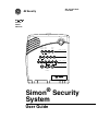
User Guide
466-1871-01 Rev A
June 2004
Simon
®
Security
System
Part No:
60-875
600-1012

FCC Notices
FCC Part 15 Information to the User
Changes or modifications not expressly approved by GE Security can void the user’s authority to operate the equipment.
FCC Part 15 Class B
This equipment has been tested and found to comply with the limits for a Class B digital device, pursuant to part 15 of the FCC Rules. These limits are designed
to provide reasonable protection against interference in a residential installation.
This equipment generates, uses, and can radiate radio frequency energy and, if not installed and used in accordance with the instructions, may cause harmful
interference to radio communications. However, there is no guarantee that interference will not occur in a particular installation.
If this equipment does cause harmful interference to radio or television reception, which can be determined by turning the equipment off and on, the user is
encouraged to try to correct the interference by one or more of the following measures:
• Reorient or relocate the receiving antenna.
• Increase the separation between the equipment and receiver.
• Connect the affected equipment and the panel receiver to separate outlets, on different branch circuits.
• Consult the dealer or an experienced radio/TV technician for help.
FCC ID: B4Z-787E-SIMON
ACTA Part 68
This equipment complies with Part 68 of the FCC Rules. Located on this equipment is a label that contains, among other information, the FCC registration num-
ber and the ringer equivalence number (REN) for this equipment. If requested, this information must be provided to the telephone company.
FCC Part 68 Registration No. B4ZUSA-27621-AL-E REN: 0.2B
The REN is used to determine the maximum number of devices that may be connected to your telephone line. Excessive RENs on a telephone line may result in
devices not ringing in response to an incoming call. In most areas, the sum of all device RENs should not exceed five (5.0). To be certain of the number of
devices that may be connected to a line, as determined by the total RENs, contact the local telephone company. For products approved after July 23, 2001, the
REN for this product is part of the product identifier that has the format US:AAAEQ##TXXXX. The digits represented by ## are the REN without a decimal
point (e.g., 03 is a REN of 0.3). For earlier products, the REN is separately shown on the label.
A plug and jack used to connect this equipment to the premises wiring and telephone network must comply with the applicable FCC Part 68 rules and require-
ments as adopted by ACTA. A compliant telephone cord and modular plug is provided with this product. It is designed to be connected to a compliant modular
jack that is also compliant. See the Installation Instructions for details.
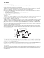
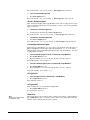
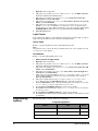
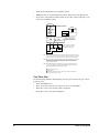
Alarm dialing equipment must be able to seize the telephone line and place a call in an emergency situation. It must be able to do this even if other equipment
(telephone, answering system, computer modem, etc.) already has the telephone line in use. To do so, alarm dialing equipment must be connected to a properly
installed RJ31X jack that is electrically in series and ahead of all other equipment attached to the same telephone line. Proper installation is depicted in the fol-
lowing diagram. If you have any questions concerning these instructions, consult your local telephone company or a qualified installer about installing an RJ31X
jack and alarm dialing equipment for you.
If this equipment causes harm to the telephone network, the telephone company may temporarily disconnect your service. If possible, you will be notified in
advance. When advance notice is not practical, you will be notified as soon as possible. You will also be advised of your right to file a complaint with the FCC.
The telephone company may make changes in its facilities, equipment, operations, or procedures that could affect the operation of the equipment. You will be
given advance notice in order to maintain uninterrupted service.
If you experience trouble with this equipment, please contact the company that installed the equipment for service and/or repair information. The telephone com-
pany may ask you to disconnect this equipment from the network until the problem has been corrected or you are sure that the equipment is not malfunctioning.
This equipment may not be used on coin service provided by the telephone company. Connection to party lines is subject to state tariffs.
Patent Information
This product and the use of this product may be covered by one or more of the following patents: 5,805,063, 5,872,512, 5,942,981, 5,686,896, 5,686,885,
4,855,713. Except expressly provided herein, the purchase of this product shall not constitute a license or otherwise provide a right to practice a method covered
by any of the identified patents. GE Security hereby grants the purchaser of this product a limited, non-exclusive license to practice the methods patented in the
identified patents solely with products manufactured, sold or licensed by GE Security. This license grant does not extend to the use of unlicensed, third party
products with this product.
N e t w o r k
S e r v ic e
P r o v id e r 's
F a c ili t ie s
T e le p h o n e
L in e
N e t w o r k
D e m a r c a t io n
P o in t
T e le p h o n e
A n s w e r in g
S y s te m
F a x M a c
h in e
C o m p u t e r
T e le p h o n e
T e le p h o n e
A la r m D ia lin g
E q u ip m e n t
R J 3 1 X
J a c k
U n u s e d
R J - 1 1 J a c k
U n u s e d
R J - 1 1 J a c k
C u s t o m e r P r e m i s e s E q u i p m e n t a n d W i r i n g

Canada Notice
The Canadian Department of Communications label identifies certified equipment. This certification means that the equipment meets certain telecommunica-
tions network protective, operational, and safety requirements. The department does not guarantee the equipment will operate to the user’s satisfaction.
Before installing this equipment, users should ensure that it is permissible to be connected to the facilities of the local telecommunications company. The
equipment must also be installed using an acceptable method of connection. In some cases, the company’s inside wiring associated with a single-line individ-
ual service may be extended by means of a certified connector assembly (telephone extension cord). The customer should be aware that compliance with the
above conditions may not prevent degradation of service in some situations.
Repairs to certified equipment should be made by an authorized Canadian maintenance facility designated by the supplier. Any repairs or alterations made by
the user to this equipment, or equipment malfunctions, may give the telecommunications company cause to request the user to disconnect the equipment.
For your protection, make sure that the electrical ground connections of the power utility, telephone lines, and internal metallic water pipe system, if present,
are connected together
The Load Number (LN) assigned to each terminal device denotes the percentage of the total load to be connected to a telephone loop which is used by the
device, to prevent overloading. The termination on a loop may consist of any combination of devices subject only to the requirement that the total of the LNs
of all the devices does not exceed 100. Load Number: .1 The term “IC:” before the certification/registration number only signifies that the Industry Canada
technical specifications were met. IC: 867A 787SIMON
“AVIS: - L
´
étiquette du ministère des Communications du Canada identifie le matériel homologué. Cette étiquette certifie que le matériel est conforme a cer-
taines normes de protection, d ´ exploitation et de sécurité des réseaux de télécommunications. Le ministère n ´ assure toutefois pas que le matériel fonction-
nera a la satisfaction de l ´ utilisateur.
Avant d ´ installer ce matériel, l ´ utilisateur doit s ´ assurer qu´ il est permis de le raccorder aux installations de l ´ enterprise locale de télécommunication. Le
matériel doit également etre installé en suivant une méthod acceptée de raccordement. Dans certains cas, les fils intérieurs de l´ enterprise utilisés pour un ser-
vice individuel a ligne unique peuvent etre prolongés au moyen d´ un dispositif homologué de raccordement (cordon prolongateur téléphonique interne). L ´
abonné ne doit pas oublier qu ´ il est possible que la conformité aux conditions énoncées ci-dessus n ´ empechent pas le dégradation du service dans certaines
situations. Actuellement, les enterprises de télécommunication ne permettent pas que l ´ on raccorde leur matériel a des jacks d ´ abonné, sauf dans les cas
précis prévus pas les tarrifs particuliers de ces enterprises.
Les réparations de matériel homologué doivent etre effectuées pas un centre d ´ entretien canadien autorisé désigné par le fournisseur. La compagne de télé-
communications peut demander a l ´ utilisateur de débrancher un appareil a la suite de réparations ou de modifications effectuées par l ´ utilisateur ou a cause
de mauvais fonctionnement.
Pour sa propre protection, l ´ utilisateur doit s ´ assurer que tous les fils de mise a la terre de la source d ´ énergie électrique, des lignes téléphoniques et des
canalisations d ´´ eau métalliques, s ´ il y en a, sont raccordés ensemble. Cette précaution est particulièrement importante dans les régions rurales.
Avertissment. - L ´ utilisateur ne doit pas tenter de faire ces raccordements lui-meme; il doit avoir recours a un service d ´ inspection des installations élec-
triques, ou a electricien, selon le cas”.
Une note explicative sur les indices de charge (voir 1.6) et leur emploi, a l ´ intention des utilisateurs du matériel terminal, doit etre incluse dans l ´ informa-
tion qui accompagne le materiel homologué. La note pourrait etre rédigée selon le modèle suivant:
“L ´ indice de charge (IC) assigné a chaque dispositif terminal indique, pour éviter toute surcharge, le pourcentage de la charge totale qui peut etre raccordée
a un circuit téléphonique bouclé utilisé par ce dispositif. La terminaison du circuit bouclé peut etre constituée de n ´ import somme des indices de charge de l
´ ensemble des dispositifs ne dépasse pas 100.”
L ´ Indice de charge de cet produit est ____________.
Do not attempt to make connections yourself. Contact the appropriate electrician or elec-
Do not attempt to make connections yourself. Contact the appropriate elec
!
tric inspections authority.
Caution
!

)
*(6HFXULW\

i
Contents
Introduction to Your Security System 1
Security System Components ..................................................................................................................... 1
How You Communicate to Your System 2
Control Panel .............................................................................................................................................. 2
Remote Handheld Touchpad....................................................................................................................... 2
Dialog QS 1500 Touchtalk Interactive Keypad.......................................................................................... 2
Keychain Touchpad .................................................................................................................................... 3
Telephone.................................................................................................................................................... 3
Computer .................................................................................................................................................... 3
How to Use Your Control Panel 3
HOME SECURITY .................................................................................................................................... 3
Arm ......................................................................................................................................................... 3
Disarm..................................................................................................................................................... 3
System Status.......................................................................................................................................... 3
Exit Delay ............................................................................................................................................... 3
Entry Delay............................................................................................................................................. 4
Quick Exit............................................................................................................................................... 4
Latchkey.................................................................................................................................................. 4
Subdisarm ............................................................................................................................................... 4
CODE.......................................................................................................................................................... 5
HOME CONTROL..................................................................................................................................... 6
Chime Doors........................................................................................................................................... 6
Chime Special Motion ............................................................................................................................ 6
Direct Bypassing..................................................................................................................................... 6
Direct Unbypassing................................................................................................................................. 6
Time Activated Lights ............................................................................................................................ 6
Sensor Activated Lights.......................................................................................................................... 7
Controlling Individual Lights ................................................................................................................. 7
All Lights On .......................................................................................................................................... 7
All Lights Off.......................................................................................................................................... 7
Silent Exit ............................................................................................................................................... 7
EMERGENCY............................................................................................................................................ 8
How Your System Communicates to You 8
Panel Voice Messages................................................................................................................................. 8
Status Beeps................................................................................................................................................ 8
Alarm Sirens and Lamp Modules ............................................................................................................... 9
Panel Indicator Lights................................................................................................................................. 9
Numeric Pager ............................................................................................................................................ 9
Dialog QS 1500 Touchtalk Interactive Keypad........................................................................................ 10
Canceling and Preventing Accidental Alarms 10
Canceling Accidental Alarms ................................................................................................................... 10

ii
Guidelines for Preventing Accidental Alarms.......................................................................................... 10
How to Use an Off-Site Phone 10
Using Touchpads and Keypads 11
Touchpads and Keypads ........................................................................................................................... 11
System Status........................................................................................................................................ 11
ARM Doors & Windows ...................................................................................................................... 11
ARM Motion Sensors ........................................................................................................................... 12
Disarm................................................................................................................................................... 12
Subdisarm ............................................................................................................................................. 12
Lights .................................................................................................................................................... 12
Emergency ............................................................................................................................................ 12
Keychain Touchpad .................................................................................................................................. 12
Using a Computer 13
RF Thermostat Operation 13
Programming Your System 13
Programming Instructions......................................................................................................................... 14
Access Codes ............................................................................................................................................ 15
Light Control............................................................................................................................................. 16
House Code........................................................................................................................................... 16
Unit Number ......................................................................................................................................... 16
Programming Options 16
Option 01 - Status Beeps .......................................................................................................................... 17
Option 02 - Panel Voice ............................................................................................................................ 17
Option 03 - Latchkey Time....................................................................................................................... 18
Option 36 and 37- Sensor Activated Light Lockout Start and Stop Times .............................................. 18
Option 36: Sensor Activated Light Lockout Start Time....................................................................... 18
Option 37: Sensor Activated Light Lockout Stop Time ....................................................................... 19
Option 41 - Voice Chime .......................................................................................................................... 19
Option 42 - Speaker Level........................................................................................................................ 20
Option 43 - Pager/Voice Event Notification Phone Number.................................................................... 20
Option 55: Status Sounds.......................................................................................................................... 21
Option 81: Heating Set Point.................................................................................................................... 22
Option 82: Cooling Set Point.................................................................................................................... 22
Trouble Beeps 23
AC Power Failure ..................................................................................................................................... 23
System Battery Failure.............................................................................................................................. 23
Restoration of Power ................................................................................................................................ 23
Sensor Failure ........................................................................................................................................... 24
Sensor Low Battery .................................................................................................................................. 24
Fail-To-Communicate............................................................................................................................... 24
Sensor Open.............................................................................................................................................. 24

iii
Sensor Tampered....................................................................................................................................... 24
Option 50 Detected ................................................................................................................................... 24
Siren 1 or 2 Failure ................................................................................................................................... 24
System Access Alarm ............................................................................................................................... 24
Testing 25
Testing Sensors ......................................................................................................................................... 25
Testing Communication............................................................................................................................ 26
Setting the Clock....................................................................................................................................... 26
Alarm System Limitations 26
Service ...................................................................................................................................................... 27
Planning for Emergencies 27
Emergency Planning ................................................................................................................................. 27
Your Floor Plan......................................................................................................................................... 28
Access Codes ........................................................................................................................................ 31
Delay Times .......................................................................................................................................... 31
Quick Reference Table Back Page

iv

Simon Security System 1
Introduction to
Your Security
System
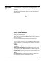
Your security system uses wireless technology to warn your family about intrusion,
carbon monoxide and fire. It may also be used to control lights and appliances within
your home. The system has the capabilities of communicating with a central monitor-
ing station and sending messages to a numeric pager or remote phone (voice event
notification).
This manual describes how to operate your system. It will guide you through program-
ming instructions for system features as well as basic arming and disarming com-
mands for the system.
Security System Components
The security system uses devices called sensors that use radio waves to communicate
alarms to the Control Panel (panel).
The system is supervised, meaning that the panel checks the status of each sensor to
detect problems. If the panel detects trouble it will notify you with beeps and indicator
lights on the panel itself.
Your security system installation may include any of the following devices:
Control Panel
The Control Panel is used to operate and program your security system. It communi-
cates to you through voice messages, beeps, and by lighting or flashing buttons. The
panel can communicate to a central monitoring station, numeric pager, remote phone,
or all three.
Touchpads
Remote Handheld Touchpads are used to control the security system primarily from
within the home.
* Dialog QS 1500 Touchtalk Interactive Keypads are used to control the security
system primarily from within the home. It’s used to hear commands from the control
panel when it’s active.
Keychain Touchpads are used to control the security system from within or near the
outside of your home. These touchpads can either be 2 or 4-button.
Sensors
Indoor Motion Sensors detect motion in a protected indoor area. When motion is
detected the panel may respond by sounding chimes or an alarm.

Simon Security System
2
Outdoor Motion Sensors detect motion in a protected outdoor area. When motion is
detected, the system may respond by sounding chimes or turning on outside lights.
These sensors are not used for intrusion detection.
Door/Window Sensors detect the opening of a door or window.
Smoke Sensors detect smoke and a significant rise in temperature. They have a built in
siren that sounds when smoke or a significant rise in temperature is detected.
Freeze Sensors detect furnace failure. If the inside temperature drops below 41
°F, the
sensor will notify the panel. The sensor will send a restore signal to the panel when the
temperature rises to 50
°F.
Carbon Monoxide Sensors detect carbon monoxide. They have a built in siren that
sounds when carbon monoxide is detected.
Modules
* Appliance Modules can be programmed to turn appliances or fluorescent lights on
and off.
* Lamp Modules can be programmed to turn non-fluorescent lights on and off.
* Universal Modules are primarily used for controlling devices other than appliances
and lamps. Check with your installer for other applications.
Audio Verification Module (AVM) is primarily used by the central monitoring station
to monitor sounds and verbally communicate with a person inside the home. This fea-
ture is similar to a speaker phone feature on a phone.
* Dialog RF Electronic Thermostat is primarily used to monitor and control HVAC
systems from the security system.
* Water Resistant Personal Help Button is a wireless device used for activating
police, medical or auxiliary alarms through your security system.
* Dialog Telephone Interface Module is a battery operated communication link
between the security system control panel and the central monitoring station.
* Ethernet Interface Module is designed to provide access to the panel via a computer
and the premisesconnect.com website.
• Installers - to aid in installation and maintenance of security systems.
• Dealers - to simplify customer and account management.
• First Responders - to identify where and how to respond.
• Customers - to control their security system.
* Not investigated for use by UL
How You
Communicate
to Your System
Sending commands or instructing your security system can be done through the panel,
touchpads, a remote telephone or a computer.
Control Panel
Note
The Master Access Code
default is 1-2-3-4 when the
security system is shipped
from the factory. You should
change your code after your
system is installed (see
“Programming Your Sys-
tem”).
You can enter commands for your security system through simple key presses on the
panel. Depending on how your system is programmed, you may need to enter an access
code for certain commands. An access code is a numeric code that allows authorization
to operate your security system.
Remote Handheld Touchpad
This touchpad gives you the option to enter commands from any room in your house.
You can enter commands through simple key presses on the touchpad.
Dialog QS 1500 Touchtalk Interactive Keypad
This keypad gives you the option to enter commands from a remote location (away
from the control panel) in your house. It also allows you to hear panel messages when
the System Status button is pressed.

Simon Security System 3
Keychain Touchpad
Keychain Touchpads are handy for simple arming, disarming and light control func-
tions. They are portable and can be carried off-site in a purse or pocket.
Telephone
Touchtone telephones can be used to communicate with your system while you are
off-site. Ask your installer if you have this feature.
Computer
With the addition of the Ethernet Interface module a computer can be used to control
your system.
How to Use
Your Control
Panel
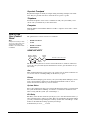
The panel interface consists of four rows of buttons.
Note
It may be necessary to enter
an access code to arm your
system. Check with your
installer to see if this feature
is enabled.
• HOME SECURITY
•CODE
• HOME CONTROL
•EMERGENCY
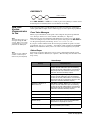
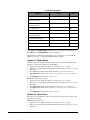
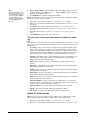
HOME SECURITY
The Home Security buttons are used to arm and disarm doors, windows and motion
sensors in your system. The System Status button is used to give information on sys-
tem activity.
Arm
Turn on intrusion/burglary protection for your system. You can arm door/window sen-
sors, motion sensors or both depending on the buttons you press.
Disarm
Turn off intrusion/burglary protection for your system. Only intrusion/burglary sensors
such as doors/windows and motion are disarmed. Environmental sensors, such as
smoke and carbon monoxide stay active at all times.
System Status
Press to hear information about your system. If the button is lit, there is a problem with
the system. If the button is blinking, an alarm has occurred. Press the button to hear
what is wrong with the system. (See “Status Beeps”.)
Exit Delay
Exit Delay is the amount of time the system gives you to exit the home before the sys-
tem is armed (between 5 and 254 seconds). This is programmed by the installer. When
you arm you will hear beeps during the exit delay (see the table “Status Beeps” of this
manual to determine the meaning of panel/system beeps).
Your Exit Delay is set for ___ seconds.
H O M E S E C U R I T
Y
S ta t u s
S y s t e m
S e n s o r s
M o t io n
D is a r m
W
in d o w s
D o o r s &
A r m

Simon Security System
4
Entry Delay
Entry Delay is the amount of time the system gives you to disarm the system after enter-
ing the home (between 5 and 254 seconds). This is programmed by the installer. When
you enter your home you will hear beeps during the entry delay (see the table “Status
Beeps” of this manual to determine the meaning of panel/system beeps).
Your Entry Delay is set for ___ seconds.
Quick Exit
Note
The designated door may be
opened and closed once. If
you close the designated
door behind you when you
exit, you will have to disarm
the system upon reentering.
Leave the designated door
open while using the Quick
Exit feature.
The Quick Exit feature is used when someone wants to briefly leave while the home is
still armed (i.e. get the newspaper). This feature needs to be enabled by your installer.
When you press the Disarm button the panel will announce exit time on. This will allow
a designated exit door to be open for up to 2 minutes without triggering an alarm.
Latchkey
Latchkey is used to notify parents, via a numeric pager or remote phone, if children do
not arrive home at a predetermined time and disarm the system. For example, you set
the Latchkey time for 3:00 pm. If the system isn’t disarmed by that time a message is
sent to your numeric pager (see “Numeric Pager”) or remote phone.
Subdisarm
If your system includes 24-hour protection sensors on items such as gun or jewelry
cases, you must subdisarm the panel before accessing these areas to avoid causing an
alarm. Environmental sensors, such as smoke and carbon monoxide stay active at all
times.
¾
Arming Your System with Doors & Windows Closed
1. Close all doors and windows.
2. Press Arm Doors & Windows button.
3. Enter Access Code (if needed).
Panel announces, Doors and windows on, Arm Doors & Windows light will be lit and
the exit delay will begin.
¾
Arming Your System with Doors or Windows Open (Indirect Bypassing)
1. Close all doors and windows except the ones you wish to remain open.
2. Press Arm Doors & Windows button.
3. Enter Access Code (if needed).
Note
Any sensors that are
bypassed by the system will
NOT be protecting your
home.
Panel announces any protected doors or windows that are open. Any sensors that are
open when the system is armed will be bypassed automatically after exit. Arm Doors &
Windows light will be lit and the exit delay will begin.
¾
Arming Your System with No Entry Delay
Note
No Entry Delay can be used
in two ways. First, you can
use this feature when you’re
staying at home, after you’ve
armed the system (i.e. when
you’re asleep). Second, you
can use this when you’re
away from your home. To
avoid causing an alarm, you
must disarm the system with
a remote handheld touchpad
or keychain before entering
your home. Check with your
installer to find out how this
option is programmed.
1. Close all doors and windows.
2. Press Arm Doors & Windows button twice.
3. Enter Access Code (if needed).
Panel announces, Doors and windows on, no entry delay. Arm Doors & Windows light
will blink and the exit delay will begin.
¾
Arm Motion Sensors
1. Press Arm Motion Sensors button once.
2. Enter access code (if needed).

Simon Security System 5
Note
This feature is most likely
used when there is no one
on the premises.
Panel announces, Motions on. Arm Motion Sensors light will be lit and the exit delay
will begin.
¾
Activate Latchkey Feature
1. Press the Arm Motion Sensors button twice.
2. Enter Access Code (if needed).
Panel announces, Motions on, Latchkey on. Arm Motion Sensors light will blink and
the exit delay will begin.
¾
Disarming Your System
1. Upon reentering your home the entry delay will begin.
2. Status beeps will sound.
3. Enter your access code using the Code buttons.
Panel announces, System disarmed and the Disarm light will be lit.
¾
Subdisarm Your System
1. Enter your Master Access Code while the system is disarmed.
Panel announces, System disarmed. Disarm button light blinks and the system is sub-
disarmed. When you’ve finished accessing the protected areas, press the Disarm but-
ton again. Panel announces, System disarmed. Disarm button light stops blinking.
System is in Disarm mode.
If You Never Leave After Arming
Your panel can be programmed to recognize that you never left the premises. If you
press the Arm Doors & Windows button and the Arm Motion Sensors button but
don’t exit before the exit delay expires, the panel will not arm the motion sensors.
Check with your installer to find out if this feature is enabled for your panel.
If You Forgot Something After Arming
Your panel can be programmed to recognize when you leave the premises then quickly
reenter. The panel will restart the exit delay to give you time to collect your things and
leave again. You must leave before the exit delay expires or disarm the system. Ask
your installer if this feature is enabled for your system.
Arming When the Panel Battery is Low
Your panel may be programmed so that you cannot arm the system if the panel battery
is low. Ask your installer if this feature is enabled for your system.
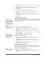
CODE
Note
40 keypresses for invalid
codes (i.e. 10 invalid 4-digit
codes) will cause a system
access alarm. The alarm
locks all touchpads, except
keychains, for 90 seconds.
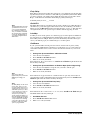
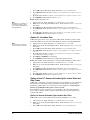
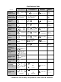
There are 5 CODE buttons located in the second row of the panel. Each button repre-
sents 2 numbers. The left CODE button is 1/2, which means that this button is pressed
when entering either 1 or 2. For example, if your access code is 1-2-3-4 you must press
the 1/2 button twice and the 3/4 button twice to enter that access code. Access code
lengths need to be between 3 and 6 digits and are set by the installer.
If you enter you home and you hear alarm sirens, or if controlled lights that
should be off are on, an intruder may be inside or another emergency may
!
have occurred. Leave immediately and call for help.
Warning
!
C O D E
9 / 05 / 6 7 / 81 / 2 3 / 4

Simon Security System
6
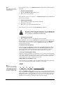
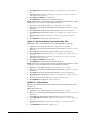
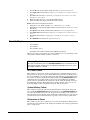
HOME CONTROL
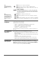
The Home Control buttons are used to monitor activity within and around the home.
They are not used for intrusion protection. If any of the Home Control buttons are
pressed and a sensor or module is not associated (programmed) with this feature the
panel will announce, Function not available.
Chime Doors
Chime Doors is used to signal (chime) when a protected door is opened while the sys-
tem is disarmed. The panel will announce the door that has been tripped and chime
twice (ask your installer how this feature is programmed). This is a nice feature to use if
you’re busy in one part of your home and you want to know when family members are
going in and out of your home.
¾
Turn Chime Doors on:
1. System must be disarmed. Press Chime Doors button.
Panel will announce, Chime on. Chime Doors button will be lit.
¾
Turn Chime Doors off:
1. Press Chime Doors button
Panel will announce, Chime off. Chime Doors button no longer lit
Chime Special Motion
Note
If there are no Special
Motion Chime sensors in
your system, the Chime
Special Motion button can
be used for Direct Bypassing
and Unbypassing. See the
Arming Your System with
Direct Bypassing and Arm-
ing Your System with
Direct Unbypassing sec-
tions for more information.
This is used to detect movement within a specific area. These Motion Sensors are not
used for intrusion protection. The panel will chime three times and announce (see
Option 41) the sensor that has been tripped. Use the same panel procedures as Chime
Doors, except, with the Chime Special Motion button.
If you have Motion Sensors located in areas such as in a patio area or at the front door
and you want to know when someone is approaching these areas, you would use this
feature.
Direct Bypassing
Direct Bypassing refers to turning off (bypassing) certain sensors while the system is
armed.
Note
You can only use this feature
if there are no Special
Motion Chime sensors in
your system.
1. Press the Bypass button until you reach the sensor to be bypassed (sensor must cur-
rently be unbypassed).
2. Enter Master Code
Direct Unbypassing
Direct Unbypassing refers to turning on (reactivating) bypassed sensors while the sys-
tem is armed.
Note
You can only use this feature
if there are no Special
Motion Chime sensors in
your system.
1. Press the Bypass button until you reach the sensor to be unbypassed (sensor must
currently be bypassed).
2. Enter Master Code. OR Change arming level.
Time Activated Lights
Turn on designated lights (with Lamp Modules) at a specific time. You can program
what time the lights go on and off (see Programming - Light Control).
¾
Turn Time Activated Lights on:
1. Press Time Lights button.
H O M E C O N T R O L
O f fO n
S e n s o rT im e
L ig h t s
M o t io nD o o r s
C h im e
B y p a s s

Simon Security System 7
Panel will announce, time activated light on. Time Lights button will be lit.
¾
Turn Time Activated Lights off:
1. Press Time Lights button.
Panel will announce, time activated light off. Time Lights button no longer lit.
Sensor Activated Lights
Turn on designated lights (with Lamp Modules) when a sensor is tripped. You can pro-
gram lockout times when Sensor Activated Lights won’t be active (see Programming
Options 36 and 37).
¾
Turn Sensor Activated Lights On:
1. System must be disarmed. Press Sensor Lights button.
Panel will announce, sensor activated lights on. Sensor Lights button will be lit.
¾
Turn Sensor Activated Lights Off:
1. Press Sensor Lights button.
Panel will announce, sensor activated lights off. Sensor Lights button no longer lit.
Controlling Individual Lights
Lights with even unit numbers (2, 4, 6, 8) can be controlled from either the panel or a
Remote Handheld Touchpad. Lights with odd unit numbers (1, 3, 5, 7) can only be
controlled from a Remote Handheld Touchpad. Lights with unit numbers 9-16 cannot
be individually controlled.
¾
Turn on individual lights that are controlled by Lamp Modules:
1. Press Lights On button once.
2. Press the number (2, 4, 6, 8) of the lamp module you want to turn on.
Panel will announce, light <number> on.
¾
Turn off individual lights that are controlled by Lamp Modules:
1. Press Lights Off button once.
2. Press the number (2, 4, 6, 8) of the lamp module you want to turn off.
Panel will announce, light <number> off.
All Lights On
¾Turns on lights that are controlled by Lamp Modules:
1. Press Lights On button twice.
Panel announce, Lights on.
All Lights Off
Turns off lights that are controlled by Lamp Modules.
1. Press Lights Off button twice.
Panel announces, Lights off.
Silent Exit
Note
Enabling Silent Exit doubles
the Exit Delay Time.
This feature silences the status beeps that accompany the exit delay (see Status Beeps).
Press Chime Doors after you arm the system to silence status beeps. The panel will
still beep at the beginning and end of the exit delay.

Simon Security System
8
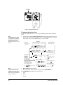
EMERGENCY
Press FIRE, POLICE, or AUX for 2 seconds (or press twice quickly) to call the central
monitoring station and notify them of a non-medical call for help.
How Your
System
Communicates
to You
Your system responds to you through the use of panel voice messages, status beeps,
alarms, panel indicator lights, and to a numeric pager or remote phone if programmed.
Panel Voice Messages
When you press the buttons on the panel or the touchpads, the panel responds with
voice messages. Panel voice can be enabled or disabled (see “Options”).
Note
The panel will not give voice
messages during an AVM
session. Talk to your security
system dealer to see if your
panel has the AVM option.
These messages may respond with system information or prompt you to take further
action. For example, if you want to disarm the system and you press the DISARM but-
ton, the panel responds by announcing, “Please enter your access code.”
If you press a button and the feature has not been programmed, the panel voice will
respond with “Function not available.” An example of this would be pressing Lights
Sensor (activated) button when you have no sensor activated lights in your system.
Status Beeps
Note
You may receive a different
number of status beeps if
buttons are pressed quickly
Status beeps are used to indicate key presses, status, and problems with the system.
They can be enabled or disabled (see “Options”). The following table describes status
beep activity.
.
E M E R G E N C Y
A U X
P O L I C EF I R E
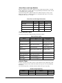
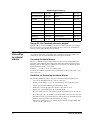
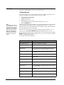
Status Beeps
Activity Beep Response
ARM Doors & Windows Exit delay and Entry delay beeps sound 2 times
every 5 seconds and 2 times per second during
the last 10 seconds (if Silent Exit is used, the Exit
delay beeps will only sound twice when you arm
and twice when the Exit delay expires)
ARM Motion Sensors Exit delay and Entry delay beeps sound 3 times
every 5 seconds and 3 times per second during
the last 10 seconds (if Silent Exit is used, the Exit
delay beeps will only sound 3 times when you arm
and 3 times when the Exit delay expires)
ARM Doors/Windows &
Motion Sensors
Exit delay and Entry delay beeps sound 4 times
every 5 seconds and 4 times per second during
the last 10 seconds (if Silent Exit is used, the Exit
delay beeps will only sound 4 times when you arm
and 4 times when the Exit delay expires)
DISARM 1 beep
CHIME DOORS 2 beeps (feature must be programmed by installer)
CHIME SPECIAL MOTION 3 beeps (feature must be programmed by installer)
Trouble Beeps 6 beeps every minute. Press the SYSTEM STA-
TUS button to stop beeps for 4 hours
No Activity Beeps 20 beeps every minute for 5 minutes (feature must
be programmed by the installer)

Simon Security System 9
Alarm Sirens and Lamp Modules
Exterior and interior sirens make 3 different alarm sounds on the premises, each indi-
cating a different type of alarm. Sirens are programmed by the installer to time-out and
stop sounding after a specified time.
Use the following table to understand the siren sounds used by the security system.
Temporal 3 refers to a continuous pattern of 3 siren pulses then off for 1.5 seconds, 3
siren pulses then off for 1.5 seconds.
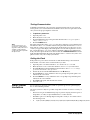
Panel Indicator Lights
Use the following table to understand the panel indicator lights.
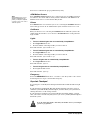
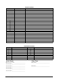
Numeric Pager
You may program your security system to send a numeric message indicating system
activities to your pager. The system will send the message twice. See “Programming
Instructions”.
Use the following table to determine what the numeric message is reporting.
Alarm Siren and X10 Light Information
Fire Intrusion Emergency
X10 Lights Steady Flashing Steady
X10 Siren Steady Steady Alarm beeps
Interior & Panel Siren Temporal 3 Steady Fast on/off
Exterior Siren Temporal 3 Steady
Panel Indicator Lights
Button
When the Button Light is
On
When the Button
Flashes
Arm Doors & Windows Doors/Windows armed Doors/Windows armed
& No Entry Delay on
Arm Motion Sensors Motion Sensors armed Motion Sensors armed
& Latchkey on
Disarm System disarmed System subdisarmed
System Status System trouble or Open Sen-
sor
System in alarm
Chime Doors Door will cause chime _________________
Chime Special Motion Motion will cause chime _________________
Time Lights Time activated lights on _________________
Sensor Lights Sensor activated lights on _________________
Numeric Pager Reporting
Reports
Numeric
Message
Reports
Numeric
Message
Phone Test -101 -101 Fail to Open -112 -112

Simon Security System
10
Dialog QS 1500 Touchtalk Interactive Keypad
With the addition of the QS 1500 Keypad, the user is able to hear the voice feedback
that is heard at the control panel. This enables the user to hear voice feedback from
remote locations (where the keypad is mounted).
Canceling and
Preventing
Accidental
Alarms
One of the biggest concerns you might have regarding your security system, is causing
an accidental alarm. Most accidental alarms occur when leaving the residence after
arming the system, or, before disarming the system upon your return.
Canceling Accidental Alarms
There is a communicator delay (Dialer Delay) of 30 seconds programmed into this
panel. The panel will delay 30 seconds before dialing the central monitoring station,
numeric pager or remote phone to send reports. You can have your installer program
this delay time between 0 - 254 seconds.
You have ___ seconds to cancel an accidental alarm.
To cancel an accidental alarm before the programmed dialer delay time expires, enter
your access code.
Guidelines for Preventing Accidental Alarms
The following guidelines will go a long way toward preventing accidental alarms.
• Close doors and windows before you leave your house.
• Gather your belongings, so you can exit immediately after arming the system.
• Always enter and exit within the programmed delay times.
• Make sure you leave through a door that has a delay time set for it.
• Disarm your system immediately upon returning home.
• Be aware of the devices in your security system and learn how each one operates.
• If you have pets, ask your installer if you need pet lenses in your motion detectors.
• Check the location of your smoke detectors. Smoke detectors near bathrooms and
kitchens can be tripped by steam and smoke from cooking.
• Take note of system beeps, voice announcements and indicator lights which indi-
cate the current system status.
AC Power Restore -102 -102 Fail to Close -113 -113
AC Power Failure -103 -103 Bypass -114 -114
Latchkey -104 -104 Restoral -115 -115
No Activity -105 -105 Supervisory -116 -116
Panic -106 -106 Trouble -117 -117
Emergency -107 -107 Tamper -118 -118
Intrusion -108 -108 Gas -119 -119
Fire -109 -109 Freeze -120 -120
Disarming -110 -110 Environmental -121 -121
Arming -111 -111 Programming/Sensor Test -122 -122
Numeric Pager Reporting

Simon Security System 11
How to Use an
Off-Site Phone
You may use an off-site phone to arm/disarm your panel, turn lights on and off, check
system status, or conduct an audio session (ask your installer if you have this feature).
¾
How to gain access to the Control Panel:
Note
You may have to perform
steps 1 & 2 more than once.
Ask your installer how your
system is programmed.
1. Call the panel phone number and let the phone ring once then hang up.
2. Wait 10 - 40 seconds and call the panel again.
3. The panel should answer on the first ring. The panel will announce “System On”.
4. Press the * button on your telephone and you will hear “System Activated”.
At this point you may perform the actions listed in the following table of phone com-
mands. CODE refers to the master and access codes programmed into your system.
If you are interactive with your panel and the panel hangs up on you, the system is
calling in a report to the central monitoring station, pager or remote phone due to an
action made by you or someone at the security system site.
Using
Touchpads and
Keypads
Touchpads and keypads are used to control the security system from any location
within or near your home.
Touchpads and Keypads
Interfacing with the system using a Remote Handheld Touchpad and Dialog QS1500
Touchtalk Interactive Keypad is similar to using the panel.
System Status
Press System Status once to hear information about your system from the panel. See
“Status Beeps”.
ARM Doors & Windows
Press Arm Doors & Windows button once to turn the security system protection on
for all protected doors and windows.
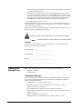
Phone Commands
Panel Function Phone Command
DISARM ‚ + CODE + 1
ARM Doors/Windows ‚ + CODE + 2
ARM Doors/Windows with No Entry Delay ‚ + CODE + 2 + 2
ARM Motions ‚ + CODE + 3
ARM Motions with Latchkey ‚ + CODE + 3 + 3
ARM Doors/Windows and Motions ‚ + CODE + 2 + 3
ARM Doors/Windows with No Entry Delay
and Motions with Latchkey
‚ + CODE + 2 + 2 + 3 + 3
Lights On/Off ‚ + CODE + 0
System Status ‚ + CODE + # + 1
AVM
Note
Phone commands cannot be used when the
panel is in AVM mode.
‚ + CODE + 5 + X (X = a command
from the Audio Verification Set, 1=Talk,
2=VOX, 3=Listen)
Hang Up ‚ + CODE + 9 (Phone Command Mode)
‚ + 99 (AVM Mode)

Simon Security System
12
Press twice to eliminate the pre-programmed entry delay.
ARM Motion Sensors
Note
Depending upon how your
dealer programmed your
panel, you may be required
to enter your access code to
arm the system.
Press Arm Motion Sensors button once to turn protection on for all Motion Sensors.
Use when no one is home. This is usually used in combination with ARM Doors &
Windows. Press twice to activate the Latchkey feature.
Disarm
Press Disarm button once and enter your access code using the NUMERIC buttons to
turn security protection off. To subdisarm the system, enter the master access code.
Subdisarm
Enter your master access code using the NUMERIC buttons while the system is dis-
armed. Panel will announce, system disarmed. The Disarm button on the panel will
begin to blink.
Lights
¾Turn on individual lights that are controlled by Lamp Modules:
1. Press Lights On button once.
2. Press the number of the lamp module you want to turn on.
Panel will announce, light <number> on.
¾
Turn off individual lights that are controlled by Lamp Modules:
1. Press Lights Off button once.
2. Press the number of the lamp module you want to turn off.
Panel will announce, light <number> off.
¾
Turn on all lights that are controlled by Lamp Modules:
1. Press Lights On button twice.
Panel will announce, lights on.
¾
Turn off all lights that are controlled by Lamp Modules:
1. Press Lights Off button twice.
Panel will announce, lights off.
Emergency
Press both EMERGENCY buttons for 3 seconds to cause the system to call a central
monitoring station to report a non-medical emergency.
Keychain Touchpad
For any keypress on the Keychain Touchpad, hold the button until the indicator light
blinks.
If your installer programmed the Keychain Touchpad with no entry delay, and you
armed the system with the Keychain Touchpad, you must disarm your system before
entering the home to avoid causing an alarm.
If your installer programmed your system for Remote Touchpad Arming, you must
enter your home to start the entry delay before you can use your Keychain Touchpad to
disarm the system.
To avoid causing false alarms, check with your installer on how your touchpad
Security system devices cannot compensate you for the loss of life
!
options are programmed
Warning
!
Page is loading ...
Page is loading ...
Page is loading ...
Page is loading ...
Page is loading ...
Page is loading ...
Page is loading ...
Page is loading ...
Page is loading ...
Page is loading ...
Page is loading ...
Page is loading ...
Page is loading ...
Page is loading ...
Page is loading ...
Page is loading ...
Page is loading ...
Page is loading ...
Page is loading ...
Page is loading ...
-
 1
1
-
 2
2
-
 3
3
-
 4
4
-
 5
5
-
 6
6
-
 7
7
-
 8
8
-
 9
9
-
 10
10
-
 11
11
-
 12
12
-
 13
13
-
 14
14
-
 15
15
-
 16
16
-
 17
17
-
 18
18
-
 19
19
-
 20
20
-
 21
21
-
 22
22
-
 23
23
-
 24
24
-
 25
25
-
 26
26
-
 27
27
-
 28
28
-
 29
29
-
 30
30
-
 31
31
-
 32
32
-
 33
33
-
 34
34
-
 35
35
-
 36
36
-
 37
37
-
 38
38
-
 39
39
-
 40
40


GE Simon Security System User manual
- Category
- Security access control systems
- Type
- User manual
- This manual is also suitable for
Ask a question and I''ll find the answer in the document
Finding information in a document is now easier with AI
Related papers

Other documents
-
SkyLink ML-100 User manual
-
Interlogix ITI Simon II User manual
-
EMC SIMON User manual
-
Mace 80200 User manual
-
-
Interlogix Concord 4 User manual
-
-
-
-
Advent home navigator User manual