Page is loading ...

)
*(,QWHUORJL[
S t a t u s
F e a t u r e s
p r e s s b o t h
L i g h t s
S y s t e m
A w a y
Q u i c k E x i t
O f f
N o D e l a y
p r e s s b o t h
p r e s s b o t h
T e s t S y s t e m W e e k l y
S i l e n t
S t a y
D
*
7
0 #
8
B
A
4
1
5
6
2
3
B y p a s s
M e n u
C
9
P r o g r a m U s e r S e t t i n g s
p r e s s 0 - 9 f o r o t h e r e n t r i e s .
P r e s s 1 f o r O F F ; p r e s s 2 f o r O N ;
P r e s s # t o s e l e c t o p t i o n o r a c c e p t e n t r
y .
0 6
0 7
0 5
0 4
1 3
1 4
1 2
1 1
A r m t o S T A Y
Q u i c k G u i d e
D i s a r m S y s t e m / C a n c e l A l a r m
i f d e s i r e d .
2
0 1
0 2
0 3
3
1
0 8
0 9
1 0
P r e s s t o d e s e l e c t o p t i o n o r c a n c e l e n t r y .
C l o s e a l l p r o t e c t e d d o o r s a n d w i n d o w s .
P r e s s 3 + C O D E .
E x i t p r e m i s e s t h r o u g h d e l a y d o o r .
2
3
1
P r e s s 2 + C O D E .
C l o s e a l l p r o t e c t e d d o o r s a n d w i n d o w s .
P r e s s 4 t o a r m d e l a y d o o r s i n s t a n t l y ,
A r m t o A W A Y
Z o n e / S e n s o r N u m b e r
P r e s s 1 + C O D E .
2
1
P r e s s A o r B t o s c r o l l t h r o u g h m e n u s .
M a k e s u r e s y s t e m i s d i s a r m e d .
2
1
P r e s s 7 + 1 t o t u r n C H I M E o n o r o f f .
M a k e s u r e s y s t e m i s d i s a r m e d .
2
1
T u r n C H I M E O n / O f f
P r e s s B Y P A S S + C O D E + S e n s o r N o .
A r m s y s t e m t o d e s i r e d l e v e l .
B y p a s s S e n s o r s
S y s t e m i s O K
S t a t u s
F e a t u r e s
p r e s s b o t h
L i g h t s
S y s t e m
A w a y
Q u i c k E x i t
O f f
N o D e l a y
p r e s s b o t h
p r e s s b o t h
T e s t S y s t e m W e e k l y
S i l e n t
S t a y
D
*
7
0 #
8
B
A
4
1
5
6
2
3
B y p a s s
M e n u
C
9
A r m e d
R e a d y
User Instructions
466-1667 Rev F
May 2003
Concord Express
Part No:
60-806
60-806-95R

FCC Notices
FCC Part 15 Information to the User
Changes or modifications not expressly approved by GE Interlogix can void the user’s authority to operate the equipment.
FCC Part 15 Class B
This equipment has been tested and found to comply with the limits for a Class B digital device, pursuant to part 15 of the FCC Rules. These limits are designed
to provide reasonable protection against interference in a residential installation.
This equipment generates, uses, and can radiate radio frequency energy and, if not installed and used in accordance with the instructions, may cause harmful
interference to radio communications. However, there is no guarantee that interference will not occur in a particular installation.
If this equipment does cause harmful interference to radio or television reception, which can be determined by turning the equipment off and on, the user is
encouraged to try to correct the interference by one or more of the following measures:
• Reorient or relocate the receiving antenna.
• Increase the separation between the equipment and receiver.
• Connect the affected equipment and the panel receiver to separate outlets, on different branch circuits.
• Consult the dealer or an experienced radio/TV technician for help.
ACTA Part 68
This equipment complies with Part 68 of the FCC Rules. Located on this equipment is a label that contains, among other information, the FCC registration num-
ber and the ringer equivalence number (REN) for this equipment. If requested, this information must be provided to the telephone company.
FCC Part 68 Registration No. B4ZUSA-27621-AL-E REN: 0.2B
The REN is used to determine the maximum number of devices that may be connected to your telephone line. Excessive RENs on a telephone line may result in
devices not ringing in response to an incoming call. In most areas, the sum of all device RENs should not exceed five (5.0). To be certain of the number of
devices that may be connected to a line, as determined by the total RENs, contact the local telephone company. For products approved after July 23, 2001, the
REN for this product is part of the product identifier that has the format US:AAAEQ##TXXXX. The digits represented by ## are the REN without a decimal
point (e.g., 03 is a REN of 0.3). For earlier products, the REN is separately shown on the label.
A plug and jack used to connect this equipment to the premises wiring and telephone network must comply with the applicable FCC Part 68 rules and require-
ments as adopted by ACTA. A compliant telephone cord and modular plug is provided with this product. It is designed to be connected to a compliant modular
jack that is also compliant. See the Installation Instructions for details.
Alarm dialing equipment must be able to seize the telephone line and place a call in an emergency situation. It must be able to do this even if other equipment
(telephone, answering system, computer modem, etc.) already has the telephone line in use. To do so, alarm dialing equipment must be connected to a properly
installed RJ31X jack that is electrically in series and ahead of all other equipment attached to the same telephone line. Proper installation is depicted in the fol-
lowing diagram. If you have any questions concerning these instructions, consult your local telephone company or a qualified installer about installing an RJ31X
jack and alarm dialing equipment for you.
If this equipment causes harm to the telephone network, the telephone company may temporarily disconnect your service. If possible, you will be notified in
advance. When advance notice is not practical, you will be notified as soon as possible. You will also be advised of your right to file a complaint with the FCC.
The telephone company may make changes in its facilities, equipment, operations, or procedures that could affect the operation of the equipment. You will be
given advance notice in order to maintain uninterrupted service.
If you experience trouble with this equipment, please contact the company that installed the equipment for service and/or repair information. The telephone com-
pany may ask you to disconnect this equipment from the network until the problem has been corrected or you are sure that the equipment is not malfunctioning.
This equipment may not be used on coin service provided by the telephone company. Connection to party lines is subject to state tariffs.
N e t w o r k
S e r v i c e
P r o v i d e r ' s
F a c i l i t i e s
T e l e p h o n e
L i n e
N e t w o r k
D e m a r c a t i o n
P o i n t
T e l e p h o n e
A n s w e r i n g
S y s t e m
F a x M a c
h i n e
C o m p u t e r
T e l e p h o n e
T e l e p h o n e
A l a r m D i a l i n g
E q u i p m e n t
R J 3 1 X
J a c k
U n u s e d
R J - 1 1 J a c k
U n u s e d
R J - 1 1 J a c k
C u s t o m e r P r e m i s e s E q u i p m e n t a n d W i r i n g

Canada Notice
The Canadian Department of Communications label identifies certified equipment. This certification means that the equipment meets certain telecommunica-
tions network protective, operational, and safety requirements. The department does not guarantee the equipment will operate to the user’s satisfaction.
Before installing this equipment, users should ensure that it is permissible to be connected to the facilities of the local telecommunications company. The equip-
ment must also be installed using an acceptable method of connection. In some cases, the company’s inside wiring associated with a single-line individual ser-
vice may be extended by means of a certified connector assembly (telephone extension cord). The customer should be aware that compliance with the above
conditions may not prevent degradation of service in some situations.
Repairs to certified equipment should be made by an authorized Canadian maintenance facility designated by the supplier. Any repairs or alterations made by the
user to this equipment, or equipment malfunctions, may give the telecommunications company cause to request the user to disconnect the equipment.
For your protection, make sure that the electrical ground connections of the power utility, telephone lines, and internal metallic water pipe system, if present, are
connected together
The Load Number (LN) assigned to each terminal device denotes the percentage of the total load to be connected to a telephone loop which is used by the device,
to prevent overloading. The termination on a loop may consist of any combination of devices subject only to the requirement that the total of the LNs of all the
devices does not exceed 100. Load Number: .1 The term “IC:” before the certification/registration number only signifies that the Industry Canada technical
specifications were met. IC: 867A 787SIMON
“AVIS: - L
´
étiquette du ministère des Communications du Canada identifie le matériel homologué. Cette étiquette certifie que le matériel est conforme a cer-
taines normes de protection, d ´ exploitation et de sécurité des réseaux de télécommunications. Le ministère n ´ assure toutefois pas que le matériel fonctionnera
a la satisfaction de l ´ utilisateur.
Avant d ´ installer ce matériel, l ´ utilisateur doit s ´ assurer qu´ il est permis de le raccorder aux installations de l ´ enterprise locale de télécommunication. Le
matériel doit également etre installé en suivant une méthod acceptée de raccordement. Dans certains cas, les fils intérieurs de l´ enterprise utilisés pour un service
individuel a ligne unique peuvent etre prolongés au moyen d´ un dispositif homologué de raccordement (cordon prolongateur téléphonique interne). L ´ abonné
ne doit pas oublier qu ´ il est possible que la conformité aux conditions énoncées ci-dessus n ´ empechent pas le dégradation du service dans certaines situations.
Actuellement, les enterprises de télécommunication ne permettent pas que l ´ on raccorde leur matériel a des jacks d ´ abonné, sauf dans les cas précis prévus pas
les tarrifs particuliers de ces enterprises.
Les réparations de matériel homologué doivent etre effectuées pas un centre d ´ entretien canadien autorisé désigné par le fournisseur. La compagne de télécom-
munications peut demander a l ´ utilisateur de débrancher un appareil a la suite de réparations ou de modifications effectuées par l ´ utilisateur ou a cause de mau-
vais fonctionnement.
Pour sa propre protection, l ´ utilisateur doit s ´ assurer que tous les fils de mise a la terre de la source d ´ énergie électrique, des lignes téléphoniques et des
canalisations d ´´ eau métalliques, s ´ il y en a, sont raccordés ensemble. Cette précaution est particulièrement importante dans les régions rurales.
Avertissment. - L ´ utilisateur ne doit pas tenter de faire ces raccordements lui-meme; il doit avoir recours a un service d ´ inspection des installations électriques,
ou a electricien, selon le cas”.
Une note explicative sur les indices de charge (voir 1.6) et leur emploi, a l ´ intention des utilisateurs du matériel terminal, doit etre incluse dans l ´ information
qui accompagne le materiel homologué. La note pourrait etre rédigée selon le modèle suivant:
“L ´ indice de charge (IC) assigné a chaque dispositif terminal indique, pour éviter toute surcharge, le pourcentage de la charge totale qui peut etre raccordée a un
circuit téléphonique bouclé utilisé par ce dispositif. La terminaison du circuit bouclé peut etre constituée de n ´ import somme des indices de charge de l ´ ensem-
ble des dispositifs ne dépasse pas 100.”
L ´ Indice de charge de cet produit est ____________.
Do not attempt to make connections yourself. Contact the appropriate electrician or electric inspections
authority.
Caution
!
)
*(,QWHUORJL[

Commands at a Glance
To do this: Press:
Disarm the system.
1 + Code
Disarm the system during
Entry Delay Time.
Code (or 1 + Code)
Cancel an accidental alarm. Code (or 1 + Code)
Arm to Level 2—STAY. 2 + Code
Arm to Level 3—AWAY. 3 + Code
Send a police alarm. Press and hold both POLICE
buttons for 2 seconds.
Send an auxiliary alarm. Press and hold both AUXILIARY
buttons for 2 seconds.
Send a fire alarm. Press and hold both FIRE
buttons for 2 seconds.
Arm system with No Delay.
2 + Code + 4 or
3 + Code + 4
Arm system to send a
Latchkey page.
2 + Code + 6 or
3 + Code + 6
Bypass a sensor. Indirectly: 2 + Code + ƒ or
3 + Code + ƒ
Directly: ƒ + Code + Sensor Number
Arm system silently.
5 + 2 + Code or
5 + 3 + Code
Check the system status.
‚
Turn Chime on/off. 7 + 1
Check alarm memory. 7 + 6
Initiate a phone test. 8 + Code + 2
Initiate a sensor test. 8 + Code + 3

i
Contents
Getting to Know Your Security System 1
Overview .....................................................................................................................................................1
Control Panel ..........................................................................................................................................1
Touchpads ...............................................................................................................................................1
Wireless Panic Button .............................................................................................................................1
Door/Window Sensors ............................................................................................................................ 1
Motion Sensors .......................................................................................................................................2
Environmental Sensors ...........................................................................................................................2
Communicating with the Panel 2
Instructing the Panel ...................................................................................................................................2
How Your System Communicates with You ..............................................................................................2
Key Beeps ...............................................................................................................................................2
Status Beeps ............................................................................................................................................2
Pager Notification ...................................................................................................................................3
Indicator Lights .......................................................................................................................................3
Fire and Smoke Alarms 3
Clearing Smoke Sensors .............................................................................................................................3
What Happens When There is an Alarm ....................................................................................................3
Arming Your System 4
Level 1—OFF .............................................................................................................................................4
Arming Level 2—STAY .............................................................................................................................4
Arming Level 3—AWAY ............................................................................................................................4
Keychain Touchpad Arming 5
Quick Arm 5
Quick Exit 5
Using the Chime Feature 5
Preventing Accidental Alarms 5
Aborting Accidental Alarms .......................................................................................................................6
Guidelines for Preventing Accidental Alarms ............................................................................................6
Exit and Entry Delay Times 6
Exit Delay Example ................................................................................................................................6
Entry Delay Example ..............................................................................................................................7
Extended Delay ...........................................................................................................................................7
Exit Extension .............................................................................................................................................7

ii
No Delay—For Instant Alarm ....................................................................................................................7
Auto STAY Arming Feature .......................................................................................................................8
Arming While a Door or Window is Open 8
Bypassing a Sensor Directly .......................................................................................................................8
Bypassing a Sensor Indirectly .....................................................................................................................9
Was the Bypass Successful? .......................................................................................................................9
Checking the Status of Your System 9
Short System Status ....................................................................................................................................9
Full System Status ....................................................................................................................................10
System Alarm Sounds ...............................................................................................................................10
Panic Alarms 10
Fire Panic ..................................................................................................................................................10
Police Panic Alarm ...................................................................................................................................10
Auxiliary Panic Alarm ..............................................................................................................................11
Siren Time-out ..........................................................................................................................................11
Access Codes 11
System Master Code .................................................................................................................................11
Regular User Codes ..................................................................................................................................11
Using the Programming Menus ................................................................................................................11
Programming Access Codes .....................................................................................................................11
Changing a User Code .......................................................................................................................... 11
Erasing a User Code .............................................................................................................................12
Assigning the Direct Bypassing Attribute ............................................................................................12
The Touchpad Tamper Feature .............................................................................................................12
Setting the Time and Date 12
Adjusting System Sounds and Touchpad Brightness 13
Arming Your System Silently ...................................................................................................................13
Silent Arming on Demand ....................................................................................................................13
Arming Always Silent ..........................................................................................................................13
Adjusting the Touchpad Beeps .................................................................................................................13
Adjusting the Touchpad Display Brightness ............................................................................................14
Notification by Pager 14
Pager Messages .........................................................................................................................................15
Event Code in Page ...............................................................................................................................15
Sensor Number or User Number in Page ..............................................................................................15
Account Number in Page ......................................................................................................................16
Streamlining the Page ...............................................................................................................................16
Opening and Closing Reports 16

iii
Latchkey Paging 16
No Activity Feature 17
Using the Panel Download Feature 17
System Information 17
Testing the System 17
Automatic Test Features ...........................................................................................................................17
Manual Tests .............................................................................................................................................18
Sensor Test ............................................................................................................................................18
Phone Communication Test ..................................................................................................................18
Testing Sirens ........................................................................................................................................19
Troubleshooting 19
Trouble Beeps and Trouble Messages ......................................................................................................20
Silencing Trouble Beeps .......................................................................................................................20
Appendix A: User Sheets 21
Account Number .......................................................................................................................................21
System Sensors .........................................................................................................................................21
User Codes ................................................................................................................................................22
Touchpad Information ...............................................................................................................................23
Accidental Smoke and Fire Alarms ..........................................................................................................24
Dialer Abort ..............................................................................................................................................24
Arming Information ..................................................................................................................................24
Paging .......................................................................................................................................................25
If the Power Goes Out ..............................................................................................................................26
No Activity Time ......................................................................................................................................26
System Information ...................................................................................................................................26
Appendix B: Planning for Emergencies 26
Floor Plan Example ..................................................................................................................................26
Your Floor Plan .........................................................................................................................................27
Alarm System Limitations ....................................................................................................................28
If Your System Needs Service ..............................................................................................................29
Appendix C: Programming Your System 29
Two Methods to Program Your System ....................................................................................................29
Using Programming Menus ..................................................................................................................29
Examples of Programming Using Menus .............................................................................................30
Using Programming Shortcuts ..............................................................................................................32
Notes 33

1
Getting to Know
Your Security
System
This manual describes how to operate your system. It describes basic arming and disarming com-
mands as well as how to program system features.
The dealer or installer may have already discussed the details of your system with you. Record
your system details in the User Sheets located in Appendix A.
Overview
Your security system is made up of different parts. Each plays a special role in the system’s oper-
ation:
Control Panel
The panel is at the heart of your system. It stores the intelligence to monitor all the sensors and
devices in the system. The panel is the piece of equipment that activates sirens and initiates a call
to the central station in an alarm situation.
Touchpads
Touchpads are used to arm, disarm, and program your system.
The first touchpad is called a fixed display touchpad. It communicates by using indicator lights,
lighted text, and an 11-character display. The second touchpad is called an alphanumeric touch-
pad and communicates by displaying text on a two-line display.
Your system may also use wireless, handheld touchpads that can be carried from room to room.
Keychain touchpads are also wireless and are handy for simple arming and disarming functions.
Keychain touchpads can be carried off-site.
The installer can program the keychain touchpad to send a Police or Auxiliary panic alarm.
Wireless Panic Button
Wireless panic button touchpads are dedicated to sending one signal only—usually a Police or
Auxiliary panic alarm. Panic button touchpads are usually kept near the user.
Door/Window Sensors
Door and window sensors protect the perimeter of your home by alerting the panel when a door
or window is opened.
S t a t u s
F e a t u r e s
p r e s s b o t h
L i g h t s
S y s t e m
A w a y
P a g e r
O f f
N o D e l a y
p r e s s b o t h
p r e s s b o t h
T e s t S y s te m W e e k ly
S il e n t
S t a y
D
*
7
0 #
8
B
A
4
1
5 6
2
3
B y p a s s
M e n u
C
9
P r o g r a m U s e r S e tt i n g s
p r e ss 0 - 9 fo r o t h e r e n tr i e s.
P r e s s 1 fo r O F F ; p r e s s 2 fo r O N ;
P r e s s # t o s el e c t o p ti o n o r ac c e p t e n t r
y .
0 6
0 7
0 5
0 4
1 3
1 4
1 2
1 1
A r m t o S T A Y
Q u i c k G u i d e
D is a r m S y s t e m / C a n c e l A l a r m
if d e si r e d .
2
0 1
0 2
0 3
3
1
0 8
0 9
1 0
P r e s s to d e s e le c t o p t io n o r c a n c e l e n t r y .
C l o s e a l l p r o t e c te d d o o r s a n d w in d o w s .
P r e s s 3 + C O D E .
E x i t p r e m is e s th ro u g h d e la y d o o r .
2
3
1
P r e s s 2 + C O D E .
C l o s e a l l p r o t e c te d d o o r s a n d w in d o w s .
P r e s s 4 to a r m d el a y d o o r s i n s t a n t ly ,
A r m t o A W A Y
Z o n e /S e n s o r N u m b e r
P r e s s 1 + C O D E .
2
1
P r e s s A o r B t o s c r o l l th ro u g h m e n u s .
M a k e s u r e sy s t e m i s d is a r m e d .
2
1
P r e s s 7 + 1 to t u r n C H I M E o n o r o f f .
M a k e s u r e sy s t e m i s d is a r m e d .
2
1
T u r n C H I M E O n / O f f
P r e s s B Y P A S S + C O D E + S e n s o r N o .
A r m s y s t e m t o d e s ir e d le v e l .
B y p a s s S e n s o rs
S y s t e m i s O K
S t a t u s
F e a t u r e s
p r e s s b o t h
L i g h t s
S y s t e m
A w a y
P a g e r
O f f
N o D e l a y
p r e s s b o t h
p r e s s b o t h
T e s t S y s t e m W e e k ly
S i l e n t
S t a y
D
*
7
0 #
8
B
A
4
1
5
6
2 3
B y p a s s
M e n u
C
9
A r m e d
R e a d y
Panel
Touchpads
Door/Window Sensors
Motion Sensors
Environmental Sensors
Wireless Panic Button

2
Motion Sensors
Motion Sensors in hallways or rooms detect a person moving across the field of detection.
Environmental Sensors
Environmental sensors such as gas, smoke, and heat detectors remain alert for the presence of
fire or carbon monoxide 24 hours a day.
Communicating
with the Panel
Your system can be set up to communicate with you through:
• Status beeps
• Alarm sirens
• Touchpad text
• Pager information
Instructing the Panel
Not just anyone can walk up to a touchpad and operate your security system. Before the system
will process most commands, users are required to enter a pre-programmed 4-digit access code.
See “Access Codes” for detailed information.
Keychain touchpads that are enrolled as part of the system do not require an access code, but are
usually kept in an individual’s pocket or purse.
If you would rather use an actual key to arm and disarm the system, your security dealer can
install a special key and keyswitch in your home.
How Your System Communicates with You
Touchpads and interior sirens produce a variety of operating beeps to inform you of different sys-
tem states and operations. The fixed display touchpad also uses indicator lights.
Key Beeps
A Key beep is the tone you hear when you press a button on a touchpad. The sound confirms that
the button was pressed adequately. Key beeps can be turned on or off by the installer.
Status Beeps
Status beeps from touchpads or sirens sound when there is a change in the current status of the
system. Status beeps are not alarms, but they do warrant your attention.
There is more than one type of Status beep:
• Exit Delay beeps indicate that an arming command has been entered and the countdown to
arming has begun.
• Entry Delay beeps indicate that you’ve entered the building and the countdown to an alarm
has begun. (So disarm the system as soon as you get in!)
• Trouble beeps tell you that there is a problem with the system or one of its components.
• Chime feature beeps tell you that a door was opened.
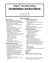
A s e n s o r i s a c t i v a t e d .
T h e s e n s o r a l e r t s t h e
p a n e l i m m e d i a t e l y .
T h e p a n e l a c t i v a t e s s i r e n s . I f t h e
s y s t e m i s m o n i t o r e d , t h e p a n e l
c a l l s t h e c e n t r a l m o n i t o r i n g s t a t i o n .
T h e c e n t r a l m o n i t o r i n g s t a t i o n
o p
e r a t o r r e p o r t s t h e a l a r m t o
t h e p o l i c e o r f i r e d e p a r t m e n t .
T h i s d e c i s i o n i s b a s e d o n s y s t e m
p r o g r a m m i n g a n d t h e c u r r e n t
a r m i n g l e v e l .

3
• Protest beeps inform you that you’re trying to arm the system while there is an open door or
window.
• Sensor test beeps are the sound the system makes during a sensor test to indicate that a sensor
was tested properly.
Status beeps are described in more detail throughout the manual.
Pager Notification
Your system can dial the phone numbers of three different pagers to notify users of events they
may want to be aware of. Some of the events include:
• when the system is disarmed,
• when the system is armed,
• trouble conditions in the system, and
• alarm conditions.
For more information, see “Notification by Pager.”
Indicator Lights
The fixed display touchpad used with Concord™ Express Systems includes ARMED and
READY indicator LEDs (light emitting diodes) that provide instant feedback.
ARMED
The red LED is the ARMED indicator. It will flash during the exit delay when you are arming the
system to level 2 (STAY) or level 3 (AWAY). It will also flash during the entry delay, before you
disarm your system.
The arming indicator will stop flashing
—but will remain on—when the exit delay expires and
the system is armed.
The arming indicator will be off when the system is disarmed.
READY
Note
Any time you notice that the
ready light is not on, you
should press the STATUS
button to find out what the
trouble condition is.
The green LED is the READY indicator. It will be on whenever the system is functioning nor-
mally. The ready indicator shuts off if the system detects a trouble condition.
Fire and Smoke
Alarms
If your system contains smoke and fire sensors, it monitors the premises for smoke and fire
alarms 24 hours a day and in all arming levels.
These alarms cannot be cancelled or aborted and are always reported to the central station. Since
many communities charge for dispatching the fire department in error, your dealer may give you
specific instructions to follow in the event of an accidental smoke or fire alarm. Record these
instructions in the Appendix A User Sheets under “Accidental Smoke and Fire Alarms.”
Clearing Smoke Sensors
Once a smoke sensor has been in alarm, it is considered “Open” or in “Trouble” until it is reset:
•Press
1 + Code once to silence the alarm, then press 1 + Code again to reset the smoke
sensor.
What Happens When There is an Alarm
In the event of an alarm, several things happen at once:
Note
Your system may or may not
be monitored. If it is not
monitored, no call will be
made.
• Sirens and hardwired touchpads emit emergency tones
• Panel notifies the central station for help.*
• Message appears on fixed display or alphanumeric touchpads.

4
Arming Your
System
Since your security needs may vary throughout the day, the system was designed with three arm-
ing levels. By arming your system to a particular level, only those sensors programmed to detect
in that arming level will report alarms.
Level 1—OFF
Use Level 1 when intrusion detection is not necessary. For example, on an active Saturday morn-
ing—kids playing inside and out; someone working in the garage; various house projects going
on.
Even though Level 1 disarms the system, your system continues to monitor for fire, smoke, car-
bon monoxide, and/or panic alarms if your system has these devices installed.
Here are some other situations in which you’d set the system to Level 1—OFF:
• Upon entering your armed home or business. When entering the armed premises through a
designated delay door, the entry delay time begins. Entry Delay beeps remind you to disarm
the system.
• Before opening a door or window while inside or outside the armed home or business. When
you wake up in the morning and want to get your newspaper, you must disarm the system
before opening the door to prevent an accidental alarm. (See the section on “Preventing Acci-
dental Alarms” if you would like to be able to leave quickly when the system is armed.)
• To stop sirens and cancel an alarm. When an alarm condition occurs, disarming the system
turns off any sirens.
¾
To disarm to Level 1—OFF using a touchpad:
1. Press 1. Touchpads display “Enter Code.”
2. Enter your access code. Touchpads display date and time or programmed text.
3. The system sounds one long beep.
Arming Level 2—STAY
There are times when you want intrusion protection, but still want the freedom to move around
within your house without setting off an alarm. For example, in the evening when your family is
inside for the night. In this and similar situations, arm your system to 2—STAY.
¾
To arm to Level 2—STAY using a touchpad:
1. Close all protected perimeter doors and windows.
2. Press
2 at any touchpad. Touchpads display, “Enter Code.”
3. Enter your access code. Touchpads display, “Armed to STAY.”
4. The system sounds two short beeps. ARMED indicators on fixed display touchpads will light
(indicator will flash during the exit delay). The exit beeps begin.
5. If leaving the premises, exit through a designated delay door immediately.
Arming Level 3—AWAY
At other times, you want every sensor to be alert: When the family is away from home, or, in a
business, after closing time.
In this and similar situations, set your system to 3—AWAY for maximum protection. All sensors
are active—perimeter door and window sensors, and interior motion detectors.
¾
To arm to Level 3—AWAY using a touchpad:
1. Close all perimeter doors and windows.
2. Press
3 at any touchpad. Touchpads display, “Enter Code.”
3. Enter your access code. Touchpads display, “Armed to AWAY.”
4. The system sounds three short beeps. ARMED indicators on fixed display touchpads will
light (indicator will flash during the exit delay). The exit beeps begin.
5. Exit through a designated delay door immediately.

5
Keychain
Touchpad
Arming
To disarm your system with a keychain touchpad, press the Unlock button.
Your installer can set up your keychain touchpad to arm the system in one of two ways:
• Press the Lock button to arm the system directly to Level 3 with no Exit delay. Using this
method, you would not be able to arm to Level 2.
• Press the Lock button to increase the arming level each time it is pressed (Level 1 to Level 2,
or Level 2 to Level 3). The Exit delay time would be applied.
Note
Your system may be configured to sound short beeps on exterior sirens when arming or disarming the
system using a keychain or wireless touchpad. This gives confirmation that an arming change was suc-
cessful even when outside. Ask your installer about this feature.
Quick Arm Your system may be set up so that you’re able to arm the system without using an access code.
¾
To use Quick Arm:
• Increase the arming level by simply pressing 2 or 3 at any touchpad.
• Decreasing the arming level requires that the user enter a code.
Quick Exit
Note
In UL Listed systems, this
feature is disabled.
Your system may be set up so that when your system is armed to Level 2—STAY, you’re able to
press
D on any touchpad and simply walk out of the door without having to disarm and rearm
the system.
This is useful when your system is armed and you want to quickly pop outside to pick up the
newspaper without disarming your system.
Important !
If you step outside and are
planning to come back in, do
not close the door behind
you!
¾ To use Quick Exit:
1. When the system is armed to 2—STAY, press D at any touchpad. You will begin to hear one
beep every five seconds. These beeps will continue throughout the 2 minute Quick Exit inter-
val.
Note
Opening the door without
pressing
D will cause the
entry delay to begin.
2. Open the door and go outside. Leave the door open if you are planning to come back in!
3. Come back in within two minutes and close the door. The system will rearm to 2—STAY.
Using the
Chime Feature
Turning on the Chime feature is like having bells on every protected door and window. When this
feature is on, sirens and speakers sound 2 beeps whenever anyone opens a protected door or win-
dow.
The Chime feature works only in Level 1—OFF.
¾
To turn Chime on/off:
• While in Level 1—OFF, from any touchpad, press 7 + 1. While the Chime feature is on,
touchpads display, “CHIME IS ON” or “Chime.”
When the system is armed again, Chime becomes deactivated.
Chime-On-Close
The Chime-On-Close feature works like the regular Chime feature, but in addition to the double
beeps heard upon opening a protected door or window, the system sounds one long beep when
the door or window is closed again.
You can turn the Chime-On-Close feature on or off from the programming menu. Refer to
Appendix C, “Programming Menus” for information on programming your system.
Preventing
Accidental
Alarms
Your security system is engineered with advanced technology that reduces the chance of an acci-
dental alarm caused by a technical problem. In wireless systems, this technology prevents other
devices, such as garage door openers, ham radios, television remote controls, and cellular
phones, from interfering with your security system.
Most accidental alarms occur when leaving the house after arming the system, or upon returning,
before disarming the system.

6
If, for example, you arm the system, then run upstairs for something you forgot, the Exit Delay
time may expire. Once the Exit Delay expires, opening an armed door or moving in front of a
motion detector will cause an alarm.
Aborting Accidental Alarms
Your system can be set up with the opportunity to abort an accidental intrusion, Police or Auxil-
iary alarm.
If the Dialer Abort feature is turned on, disarming the system within a specified time period will
silence the siren and prevent the alarm from being reported to the central monitoring station (thus
aborting the alarm). Your system will display “report aborted” for a few seconds, if you disarm
before the alarm is reported. If you don’t disarm in time to abort the central station report, the
system will automatically send an “alarm cancelled” report to the central station when the system
is disarmed. Follow the procedures of your central station to prevent a false dispatch. See “Alarm
Information” in Appendix A to determine if this feature is enabled for your system.
Fire alarms caused by smoke sensors, fire panic alarms, and heat sensors cannot be aborted. Dis-
arming a fire alarm will silence the siren, but fire alarms are always reported. If an accidental fire
alarm has sounded, follow the procedures of your central monitoring station to prevent a false
dispatch.
Note
There is a communicator delay (Dialer Abort Delay) of 30 seconds programmed into this panel. The
panel will delay 30 seconds before dialing the central monitoring station or a numeric pager to send
reports. You can have your installer program this delay time between 15 - 45 seconds.
¾ To cancel an alarm:
•Press Code (or 1 + Code.)
Guidelines for Preventing Accidental Alarms
Following these guidelines will go a long way toward preventing accidental alarms.
• Close doors and windows before you leave your house.
• When getting ready to leave the house, gather the things you want to take with you so you can
exit immediately after arming the system.
• Always enter and exit within the programmed delay times.
• Make sure you leave through a door that has a delay time set for it. If you arm your system,
then leave through a door without a delay time, an alarm will immediately sound.
• When you return, immediately disarm your system.
• Be aware of the devices in your security system and learn how each one operates.
• Listen to system beeps. Take note of any touchpad messages or lights that indicate the current
system status.
• If you have pets, ask your installer if you need pet lenses in your motion detectors. Pets climb
higher than you may guess, causing alarms when you are away.
• Check the location of your smoke detectors. Smoke detectors near bathrooms can be tripped
by steam from a shower. Smoke detectors near the kitchen can be tripped by cooking smoke.
Refer to the User Sheet in Appendix A to determine what the specific settings are for your sys-
tem.
Exit and Entry
Delay Times
After arming your system, you need time to exit the building so you won’t set off an alarm. Like-
wise, upon returning to your home or business, you’ll need enough time to open the door and get
to a touchpad to disarm the system.
•The Exit Delay is a period of time long enough to let you leave through a designated delay
door after arming the system.
•The Entry Delay is a period of time long enough to let you unlock a designated delay door
and get to a touchpad to disarm the system.
Exit Delay Example
You’re about to go on an errand. You are inside your house and have just armed the system to
Level 3—AWAY.

7
The interior sirens and touchpads sound three quick status beeps, telling you that the system
accepted the command and has started the Exit Delay time.
During the Exit Delay time, the system sounds one short beep every 4 seconds. The red ARMED
indicator light on fixed display touchpads will flash. During the last seconds of the delay time,
the beeps will accelerate to one per second. Exit the premises immediately.
At the end of the Exit Delay, you’ll hear three more quick status beeps. These beeps indicate that
the Exit Delay has ended. The ARMED indicator light on fixed display touchpads will stop flash-
ing and remain on. Opening an armed door or window after the Exit Delay has expired will cause
an alarm.
Entry Delay Example
You are returning to your house that is armed to Level 3—AWAY. When you unlock and enter
the designated delay door, the interior sirens and touchpads sound two short beeps every two sec-
onds. The red ARMED indicator light on fixed display touchpads will flash. This tells you that
the Entry Delay time has begun and reminds you to disarm the system to avoid setting off an
alarm.
During the last 10 seconds of Entry Delay, you’ll hear two short beeps every second.
Your installer will work with you to decide which door(s) should be delay door(s), and determine
the delay times that will work best for you and your family. Then, the installer will program the
Exit and Entry Delay times into your system.
Extended Delay
In some situations, additional time is needed to arm or disarm the system from, for example, a
protected outside gate or door. In these instances, the installer can program an extended delay,
giving as much as 16 minutes to exit or disarm the system before setting off an alarm.
Refer to the Appendix A User Sheets, “Delay Doors and Delay Time Settings,” for a list of actual
exit delay times.
Exit Extension
Note
In UL Listed systems, this
feature is disabled.
Your system may be set up so that the exit delay time is restarted if you reopen the delay door
during the initial exit delay time.
This is useful if, after arming the system, you walk out the door, then remember something you
forgot inside. You can reenter and exit through the delay door without disarming and rearming
the system.
Note
The Exit Extension will work
on the first re-entry only.
If your system is not using this feature, you must disarm the system when you reenter the armed
premises to avoid setting off an alarm.
No Delay—For Instant Alarm
You can choose to turn off the Entry and Exit Delays, causing the delay doors to arm immedi-
ately. Anyone entering the house through the delay door when the system is set to No Delay
would immediately cause an alarm.
No Delay is normally used:
• When you’re staying at home, after you’ve armed the system.
• When you’re arming and disarming your house from the outside. (You must have a wireless
touchpad in order to do this.)
B E E P S
A
f t e r a r m i n g ,
y
o u ' l l h e a r
3 q u i c k
s
t a t u s b e e p s .
3 q u i c k s t a t u s
b e e p s s o u n d
b e f o r e t h e s y s t e m
i s a r m e d .
D u r i n g t h e E x i t D e l a y ,
y o u ' l l h e a r
o n e b e e p e v e r y
f o u r s e c o n d s .
L e a v e t h e p r e m i s e s n o w .
B E E P S
U p o n e n t e r i n g , d u r i n g t h e
E n t r y D e l a y , y o u ' l l h e a r 2 b e e p s
e v e r
y
2 s e c o n d s .
D i s a r m t h e s y s t e m b e f o r e
t h e l a s t o f 1 0 q u i c k s t a t u s b e e p s
t o a v o i d a n a c c i d e n t a l a l a r m .

8
¾ Arming to Level 2 or 3 with No Delay:
1. Close all perimeter doors and windows.
2. Exit the premises if arming to Level 3—AWAY.
3. Enter:
2 + Code or 3 + Code.
The system sounds two or three short beeps.
4. Immediately after hearing the beeps, press
4 for No Delay.
Touchpads display an arming message, such as “Armed to STAY No Delay” or “ARMED TO
AWAY NO DELAY,” for example. The ARMED indicator light on fixed display touchpads
will light.
Changing the arming level will restore delay doors to their normal Exit and Entry Delay times.
Auto STAY Arming Feature
The Auto STAY Arming feature helps cut down on false alarms in the event that you arm the sys-
tem to 3—AWAY, but fail to leave during the exit delay time. Here’s how it works:
Your dealer can turn this feature on or off for you. See the “Arming Information” section of
Appendix A to find out if this feature is currently enabled in your system.
Arming While a
Door or Window
is Open
It is possible to arm your system while leaving a door or window open. This is useful if, for
example, you like to sleep at night with the window open.
If the door or window has a sensor installed on it, the system must be told to ignore, or bypass,
that sensor when it’s open. All other sensors will remain active.
There are two methods for bypassing a sensor:
• Directly — After arming the system, bypass door/window sensors before you open them.
You must know the sensor number of the door or window you wish to bypass. To bypass
directly, the user code must have been given the Direct Bypassing attribute. See “Assigning
the Direct Bypassing Attribute” for more information.
• Indirectly — As you are arming, bypass sensors on already-open doors and window. This
method should not be used in UL-listed installations.
Note
When a sensor is bypassed,
you are allowing that door or
window to be unprotected.
Bypassing a Sensor Directly
Use this method if the system is armed and you would like to open a window without disarming.
Refer to the Appendix A User Sheets to determine what the sensor number is for the sensor you
wish to bypass.
¾
To bypass sensors directly:
1. Close all doors and windows.
2. Arm your system to the desired level.
3. At any touchpad, press
ƒ (labeled Bypass) + Code + sensor number.
4. Touchpads display, “Bypassed Zones 01,” or “SENSOR 01 BYPASSED,” for example.
If the touchpad displays “INVALID,” or if the touchpad sounds one long beep, make sure that
you entered a valid access code and a valid sensor number. Gas, heat, and smoke sensors can-
not be bypassed.
5. Bypass other sensors, if necessary, by repeating Step 3.
If you arm the system to Level 3—AWAY, and do not leave the premises within the exit
delay time—
If feature turned on The system can tell that no one opened and closed a delay door within
the delay time. It assumes that someone is still inside and the panel will
arm to 2—STAY to avoid a false alarm.
If feature turned off The system arms to Level 3—AWAY regardless of whether or not a delay
door has been opened and closed.
Your movement inside the premises could activate a motion detector,
causing an alarm.

9
6. The bypassed door or window can now be opened.
¾
To arm bypassed sensors:
• Arm the system again.
OR
• At any touchpad, press
ƒ (labeled Bypass) + Code + sensor number.
Note
You cannot bypass sensors
directly using a keychain
touchpad.
Touchpads display, “Zones 01 OK,” or “SENSOR 01 UNBYPASSED,” for example.
If the touchpad displays “INVALID,” or if the touchpad sounds one long beep, make sure that
you entered a valid access code and a valid sensor number.
Bypassing a Sensor Indirectly
Use this method if you are arming the system and would like to bypass doors and windows
already open.
¾
To bypass sensors indirectly:
1. Leave open only those doors and windows that are to remain open. Close all others.
2. Arm your system to the desired level. The touchpad emits protest beeps and displays “PRO-
TEST,” because of the open sensor(s).
3. At any touchpad. press BYPASS. Touchpads with displays show, “Bypassed Zones 01,” or
“SENSOR 01 BYPASSED,” for example.
4. The system sounds arming level beeps to indicate that the system is armed and open sensors
have been successfully bypassed.
¾
To arm bypassed sensors:
• Arm the system again.
OR
• At any touchpad, press
ƒ (labeled Bypass) + Code + sensor number.
Touchpads display, “Zones 01 OK,” or “SENSOR 01 UNBYPASSED,” for example.
If the touchpad displays “INVALID,” or if the touchpad sounds one long beep, make sure that
you entered a valid sensor number.
¾
To bypass sensors indirectly using a keychain touchpad:
• Press the Lock button once to arm the system and again to bypass open sensors:
+
Was the Bypass Successful?
¾ To confirm whether or not a sensor was bypassed:
•Press the ‚ button (labeled Status) on the touchpad. Touchpads with displays list bypassed
sensors or zones.
Checking the
Status of Your
System
Checking the system status means finding out about the current condition of your system. This
includes finding out if any sensors are open or currently bypassed, whether or not the AC power
and backup battery are okay, the nature of the most recent alarm, and more, depending on the fea-
tures in use and the equipment in your system.
Check the system status if:
• Your system sounds trouble beeps (five short beeps every minute).
• Your touchpads display, “Zones,” “POLICE,” “AUXILIARY,” or “FIRE.”
• Your touchpads display, “Press Status” or a blinking .
• The green READY light on fixed display touchpads is off.
Short System Status
A Short Status indicates the current arming level, sensor status (whether open or bypassed), low
battery, supervisory, AC power or backup battery failures.

10
¾ To get a Short System Status:
¾ Press ‚.
The system sounds beeps according to the current arming level. (One for Level 1, two for
Level 2, three for Level 3.)
Touchpads display the status information, for example:
“System is OK,” or “SENSOR 02 OPEN.”
If an alarm or system trouble condition has occurred, it is displayed on a touchpad the first time
you perform a Short or Full Status check. Performing a system status check a second time dis-
plays the system status including any trouble conditions.
If any alarm or system trouble is active, it continues to show up in every status check until the
system is disarmed.
Full System Status
Note
A Full System Status is not
available from the fixed dis-
play touchpad.
A Full Status combines the Short Status information with added details about specific system
features.
¾
To get a Full System Status:
•Press ‚ + ‚. Interior sirens sound beeps according to the current arming level. Touchpads
display the status information, for example, “SENSOR 03 BYPASSED,” “SYSTEM BAT-
TERY IS OK,” or “AC POWER IS OK.”
System Alarm Sounds
The sirens and touchpads in your system emit alarm sounds whenever an alarm occurs, either by
a sensor or panic button activation. Each type of alarm sounds and reacts differently when acti-
vated, as described in the following table.
.
Panic Alarms Panic alarms are easily activated from any touchpad to quickly alert the central monitoring sta-
tion to a Fire, Police, or Auxiliary emergency. A panic alarm can be activated at any time, regard-
less of the current arming level: 1—OFF, 2—STAY, or 3—AWAY.
This system is designed to inform a central monitoring station of the nature of the emergency so
the correct personnel can be dispatched immediately.
Fire Panic
The Fire panic alarm sounds from all interior and exterior sirens. On monitored systems, the cen-
tral monitoring station responds by calling the fire department.
¾
To activate a Fire panic alarm from a touchpad:
• Press and hold both Fire buttons for 2 seconds.
Police Panic Alarm
The Police panic alarm sounds from all interior and exterior sirens, scaring off any intruder and
alerting neighbors to the trouble. On monitored systems, the central monitoring station responds
by calling the police.
Type of Alarm Alarm Sound
Fire
Repeating series of three beeps
Police
Continuous Tone
Auxiliary
Rapid Beeps

11
¾ To activate a Police panic alarm using a touchpad:
• Press and hold the Police button(s) for 2 seconds.
¾
To activate a Police panic alarm from a keychain touchpad*:
• Press and hold the Lock and Unlock buttons at the same time for 2 seconds.
* The installer must configure the Police panic alarm to work this way.
Auxiliary Panic Alarm
The Auxiliary panic alarm sounds from interior sirens only. It is typically set up by your security
dealer, based on your specific needs. On monitored systems, the central station responds by call-
ing the service or agency you specified through your dealer.
¾
To activate an Auxiliary panic alarm from a touchpad:
• Press and hold the Auxiliary button(s) for 2 seconds.
Siren Time-out
If the system is not disarmed after an alarm, the sirens will continue to sound until the time-out
period is reached. The time-out period can be programmed only by your installer or dealer.
Even though reaching the end of the time-out period stops the sirens, if your system is monitored,
the central station will consider the alarm in progress until the system is manually disarmed.
Access Codes The system requires a valid access code before it will process most commands. The Appendix A
User Sheets provide a location for you to record the System Master and User codes.
System Master Code
There is one System Master code. The System Master code is used to enter the programming
menus for your system. The default System Master code is
1234. It is important that you
change the default code and record the new code in the Appendix A User Sheets.
¾
To change the System Master Code:
1. Enter the programming menus by pressing 9 + the current System Master Code.
2. Press
110.
3. Enter the desired 4-digit System Master Code, then press ƒ.
4. Press
‚ + 4 + ƒ to exit the programming menus.
Regular User Codes
There are 16 Regular User codes which act like keys to arm and disarm the system. If necessary,
they can be assigned to neighbors, baby-sitters, or repair persons for temporary use. Regular user
codes can be changed in the programming menus and are easily deleted from the system when no
longer necessary.
Good User Code Hygiene
To preserve the integrity of your system, keep user codes confidential and delete extra codes as
soon as they are no longer needed.
We recommend that you avoid using obvious code patterns such as 1234 or 1111, 2222,
etc.
Using the Programming Menus
Some system settings can be changed by you, the user, while other settings must be changed by
the installer.
To change system settings, you’ll use the System Master code to enter a series of programming
menus. Appendix C gives a detailed explanation of how to use the menus or, if desired, how to
use programming shortcuts.

12
Programming Access Codes
User codes can be given certain attributes which determine whether the user can bypass a sensor
or perform system tests.
Changing a User Code
¾ To change or assign a user access code:
Note
The system will not accept
the same code for two differ-
ent users.
1. Enter the programming menus by pressing 9 + System Master Code.
2. Press 10 nn 0 where nn is user 00 through 15.
3. Enter the desired 4-digit code, then
ƒ.
4. Press
‚ + 4 + ƒ to exit the programming menus.
Erasing a User Code
When a code is deleted from the system, that code no longer acts as a key for operating the sys-
tem in any manner.
¾
To erase a user code:
1. Enter the programming menus by pressing 9 + System Master Code.
2. Press 10 n n 0 where nn is user 00 through 15.
3. Enter the System Master code, then
ƒ.
4. Press
‚ + 4 + ƒ to exit the programming menus.
Assigning the Direct Bypassing Attribute
Direct Bypassing is a user code attribute that allows the user to bypass open sensors. If the user
code does not have this attribute turned on, the user will not be able to bypass sensors directly.
¾
To assign Direct Bypassing to a user:
1. Enter the programming menus by pressing 9 + System Master Code.
2. Press
10 n n 1 where nn is user 00 through 15.
3. To turn Direct Bypassing
on, press
2 + ƒ.
off, press
1 + ƒ.
4. Press
‚ + 4 + ƒ to exit the programming menus.
Assigning the System Test Attribute
System Tests is a user code attribute that allows the user to perform system tests. If the user code
does not have this attribute turned on, the user will not be able to perform phone or sensor tests.
¾
To assign the System Testing to a user:
1. Enter the programming menus by pressing 9 + System Master Code.
2. Press
10 n n 2 where nn is user 00 through 15.
3. To turn System Testing:
on, press
2 + ƒ.
off, press
1 + ƒ.
4. Press
‚ + 4 + ƒ to exit the programming menus.
The Touchpad Tamper Feature
The installer can program your system to send a Police alarm in the case of possible touchpad
tampering.
If more than 40 keys are pressed when the system asks for a code, and those keystrokes are not
part of a valid access code, a siren will sound. See “Touchpad Information” in Appendix A to
determine if this feature is enabled for your system.

13
Setting the Time
and Date
Although the installer usually sets the time and date at the time of installation, the user can
change it when necessary. See Appendix C, “Programming Your System” for more detailed
information on setting this feature.
¾
To set the system time:
1. Enter the programming menus by pressing 9 + System Master Code.
2. Press
00.
3. Enter the correct time in 24-hour format (4 digits), then press ƒ.
For example, if the current time is 7:23 a.m., press
0723 + ƒ.
4. Press
‚ + 4 + ƒ to exit the programming menus.
¾
To set the system date:
1. Enter the programming menus by pressing 9 + System Master Code.
2. Press
01.
3. Enter the current date as 6 digits (mm/dd/yy) then press ƒ.
4. Press
‚ + 4 + ƒ to exit the programming menus.
Adjusting
System Sounds
and Touchpad
Brightness
Arming Your System Silently
Use the Silent Arming feature to arm your system without disturbing people throughout the
house with arming status beeps. There are two methods for implementing Silent Arming:
• Silent on Demand (User presses
5 before arming.)
• Arming Always Silent (Silent Arming feature on).
Regardless of the method employed, when Silent Arming is in effect, no Exit beeps sound.
Note
Protest beeps will always
sound when bypassing a
sensor.
Silent Arming on Demand
Pressing 5 before arming silences arming status beeps from touchpads and interior sirens.
¾
To use Silent Arming on demand:
1. From any touchpad, press 5.
2. Within 4 seconds enter:
2 + Code or 3 + Code.
Arming Always Silent
Note
Arming Always Silent may
have been disabled by your
installer.
Turning this feature on in the programming menu means that the status beeps that come from
touchpads and interior speakers while arming will always be silent. You will not have to enter
5 before arming, as with Silent Arming on Demand.
See Appendix C, “Programming Your System” for more detailed information on setting this fea-
ture.
¾
To enable Arming Always Silent:
Note
Exit Delay is doubled when
you enable Silent Arming.
1. Enter the programming menus by pressing 9 + System Master Code.
2. Press
2 + 1.
3. To turn Silent Arming:
on, press
2 + ƒ. No system status beeps will sound while arming.
off, press
1 + ƒ. System status beeps will sound from touchpad while arming.
2 4 - H o u r F o r m a t
6 : 0 0 a m
7 : 0 0 a m
8 : 0 0 a m
9 : 0 0 a m
1 0 : 0 0 a m
1 1 : 0 0 a m
0 0 : 0 0
0 1 : 0 0
0 2 : 0 0
0 3 : 0 0
0 4 : 0 0
0 5 : 0 0
=
=
=
=
=
=
M i d n i g h t
1 : 0 0 a m
2 : 0 0 a m
3 : 0 0 a m
4 : 0 0 a m
5 : 0 0 a m
0 6 : 0 0
0 7 : 0 0
0 8 : 0 0
0 9 : 0
0
1 0 : 0 0
1 1 : 0 0
=
=
=
=
=
=
1 2 : 0 0
1 3 : 0 0
1 4 : 0 0
1 5 : 0 0
1 6 : 0 0
1 7 : 0 0
=
=
=
=
=
=
N o o n
1 : 0 0 p m
2 : 0 0 p m
3 : 0 0 p m
4 : 0 0 p m
5 : 0 0 p m
1 8 : 0 0
1 9 : 0 0
2 0 : 0 0
2 1 : 0 0
2 2 : 0 0
2 3 : 5 9
=
=
=
=
=
=
6 : 0 0 p
m
7 : 0 0 p
m
8 : 0 0 p
m
9 : 0 0 p
m
1 0 : 0 0 p
m
1 1 : 5 9 p
m
/