Page is loading ...

Cover photo may show optional equipment not supplied
with standard unit.
© Copyright 2008 Printed
Read the Operator’s Manual entirely. When
you see this symbol, the subsequent
instructions and warningsareserious-follow
without exception. Your life and the lives of
others depend on it!
!
Table of Contents
Razor Pro
7/14/08
ZRP44 & ZRP52 Zero Turning Radius Mowers
Operator’s Manual
21041
356-117M
®
®
Accu-Z

Table of Contents
ZRP44 & ZRP52 Zero Turning Radius Mowers 356-117M
7/14/08
Land Pride
Table of Contents
© Copyright 2008 All rights Reserved
LandPride providesthispublication“asis”without warrantyofanykind,either expressedorimplied. While every precautionhasbeentakenin the preparationofthismanual,
Land Pride assumes no responsibility for errors or omissions. Neither is any liabilityassumed fordamages resulting from the use of the information contained herein.Land
Pride reserves the right to revise and improve its products as it sees fit. This publication describes the state of this product at the time of its publication, and may not reflect
the product in the future. The illustrations in this manual are not intended for safe and proper assembly or disassembly of equipment. The illustrations are intended for
ordering parts only.
Land Pride and Accu-Z Razor are registered trademarks.
All other brands and product names are trademarks or registered trademarks of their respective holders.
Printed in the United States of America.
Important Safety Information . . . . . . . . . . .1
Safety Labels . . . . . . . . . . . . . . . . . . . . . . . . . . . . . 3
Introduction . . . . . . . . . . . . . . . . . . . . . . . .6
Application . . . . . . . . . . . . . . . . . . . . . . . . . . . . . . . 6
Using This Manual . . . . . . . . . . . . . . . . . . . . . . . . . 6
Terminology . . . . . . . . . . . . . . . . . . . . . . . . . . . 6
Definitions . . . . . . . . . . . . . . . . . . . . . . . . . . . . . 6
Owner Assistance . . . . . . . . . . . . . . . . . . . . . . . . .6
Further Assistance . . . . . . . . . . . . . . . . . . . . . . 6
Section 1 Assembly and Set-Up . . . . . . . .7
Control Lever & Seat Assembly . . . . . . . . . . . . . . . 7
Section 2 Operating . . . . . . . . . . . . . . . . . .8
Controls . . . . . . . . . . . . . . . . . . . . . . . . . . . . . . . . . 8
Ignition Switch . . . . . . . . . . . . . . . . . . . . . . . . . . 8
Throttle Control . . . . . . . . . . . . . . . . . . . . . . . . . 8
Choke Control . . . . . . . . . . . . . . . . . . . . . . . . . . 8
Left/Right Fuel Tank Valve . . . . . . . . . . . . . . . .9
Blade Engagement Switch . . . . . . . . . . . . . . . .9
Control Levers . . . . . . . . . . . . . . . . . . . . . . . . . . 9
Deck Lift Pedal . . . . . . . . . . . . . . . . . . . . . . . . . 9
Instrumentation . . . . . . . . . . . . . . . . . . . . . . . . . . 10
Oil Pressure Light . . . . . . . . . . . . . . . . . . . . . . 10
Electronic Hour Meter . . . . . . . . . . . . . . . . . . . 10
Safety Start Interlock System . . . . . . . . . . . . . . . . 10
Engine Starting . . . . . . . . . . . . . . . . . . . . . . . . . . 10
Moving Mower with Stalled Engine . . . . . . . . . . . 11
Driving the Mower . . . . . . . . . . . . . . . . . . . . . . . . 11
Steering . . . . . . . . . . . . . . . . . . . . . . . . . . . . . 11
Controlling the Speed . . . . . . . . . . . . . . . . . . . 11
To Stop or decrease speed: . . . . . . . . . . . . . . 11
To Increase Speed: . . . . . . . . . . . . . . . . . . . . . 11
Operating Suggestions . . . . . . . . . . . . . . . . . . . .12
Mower Deck Operation . . . . . . . . . . . . . . . . . . . . 13
Operating Instructions . . . . . . . . . . . . . . . . . . . . . 13
Section 3 Adjustments . . . . . . . . . . . . . . .14
Introduction . . . . . . . . . . . . . . . . . . . . . . . . . . . . . 14
Torque Values . . . . . . . . . . . . . . . . . . . . . . . . . . . 14
Steering Linkage . . . . . . . . . . . . . . . . . . . . . . . . . 14
Control Lever Neutral Adjustment . . . . . . . . . . 15
Control lever stops . . . . . . . . . . . . . . . . . . . . . 15
Steering Dampener . . . . . . . . . . . . . . . . . . . . . . . 16
Control Lever Adjustment . . . . . . . . . . . . . . . . . . 16
Park Brake Adjustment . . . . . . . . . . . . . . . . . . . . 16
Hydro-Drive Belt Adjustment . . . . . . . . . . . . . . . . 18
Deck Drive Belt Adjustment . . . . . . . . . . . . . . . . . 18
Engine RPM Setting . . . . . . . . . . . . . . . . . . . . . . 19
Deck Leveling and Height Adjustment . . . . . . . . .19
Deck Level Adjustments . . . . . . . . . . . . . . . . .19
Tire Inflation Chart . . . . . . . . . . . . . . . . . . . . . . . .19
Deck Cutting Height Adjustment . . . . . . . . . . . . .21
Anti-Scalp Rollers . . . . . . . . . . . . . . . . . . . . . . . .21
Section 4 Maintenance and Lubrication .22
Maintenance . . . . . . . . . . . . . . . . . . . . . . . . . . . .24
Torque Values . . . . . . . . . . . . . . . . . . . . . . . . . . .24
Tires . . . . . . . . . . . . . . . . . . . . . . . . . . . . . . . . . . .24
Tire Inflation Chart . . . . . . . . . . . . . . . . . . . . . . . .24
Hour Meter . . . . . . . . . . . . . . . . . . . . . . . . . . . . . .25
Lubrication . . . . . . . . . . . . . . . . . . . . . . . . . . . . . .25
Electrical System . . . . . . . . . . . . . . . . . . . . . . . . .25
Burnishing the Electric Clutch . . . . . . . . . . . . . . .26
Access to Engine & Hydraulic Pumps . . . . . . . . .26
Hydraulic System . . . . . . . . . . . . . . . . . . . . . . . . .26
Fuel System . . . . . . . . . . . . . . . . . . . . . . . . . . . . .27
Draining the fuel tank . . . . . . . . . . . . . . . . . . .28
Changing fuel filters . . . . . . . . . . . . . . . . . . . . .28
Engine Oil and Filter . . . . . . . . . . . . . . . . . . . . . . .29
Engine Air Filter . . . . . . . . . . . . . . . . . . . . . . . . . .29
Over Servicing . . . . . . . . . . . . . . . . . . . . . . . . .29
Improper Installation . . . . . . . . . . . . . . . . . . . .30
Damaged filter, Seals or Canister . . . . . . . . . .30
Incorrect Air Filter Element . . . . . . . . . . . . . . .30
Engine Air Filter Service Procedure . . . . . . . . . . .30
General Engine Maintenance . . . . . . . . . . . . . . . .30
Belt Replacement . . . . . . . . . . . . . . . . . . . . . . . . .30
Deck Drive Belt . . . . . . . . . . . . . . . . . . . . . . . .31
Integrated Pump/Motor Drive Belt . . . . . . . . . .31
Deck Belt Drive Layout . . . . . . . . . . . . . . . . . .31
Pump Belt Layout . . . . . . . . . . . . . . . . . . . . . .31
Mower Blade Maintenance . . . . . . . . . . . . . . . . . .32
Mower Blade Removal and Sharpening . . . . . . . .32
STORAGE . . . . . . . . . . . . . . . . . . . . . . . . . . . . . .33
Preparation of Engine for Storage . . . . . . . . . . . .33
New Season Preparation . . . . . . . . . . . . . . . . . . .33
Section 5 Specifications and Capacities 34
Section 6 Features and Benefits . . . . . . .36
Section 7 Troubleshooting . . . . . . . . . . .37
Section 8 Appendix . . . . . . . . . . . . . . . . .39
Torque Values Chart for Common Bolt Sizes . . . .39
Tire Inflation Chart . . . . . . . . . . . . . . . . . . . . . . . .39
Warranty . . . . . . . . . . . . . . . . . . . . . . . . . . . . . . .41

1
Important Safety Information
7/14/08
ZRP44 & ZRP52 Zero Turning Radius Mowers 356-117M
Land Pride
Table of Contents
Important Safety Information
Keep Riders
Off Machinery
▲ Riders obstruct the operator’s
view, they could be struck by
foreign objects or thrown from the
machine.
▲ Never allow children to operate
equipment.
!
Be Aware of Signal Words
A signal worddesignates adegree or
level of hazard seriousness. The
signal words are:
Indicates an imminently hazardous
situation which, if not avoided, will
result in death or serious injury. This
signal word is limited to the most
extreme situations, typically for
machine components that, for
functional purposes, cannot be
guarded.
Indicates a potentially hazardous
situation which, if not avoided, could
result in death or serious injury, and
includes hazards that are exposed
when guards are removed. It may
also be used to alert against unsafe
practices.
Indicates a potentially hazardous
situation which, if not avoided, may
result in minor or moderate injury. It
may also be used to alert against
unsafe practices.
For Your Protection
▲ Thoroughly read and understand
the “Safety Label” section,read all
instructions noted on them.
!
DANGER!
!
WARNING!
!
CAUTION!
Shutdown and Storage
▲ Put mower in park, turn off
engine, and remove the key.
▲ Store in an area where children
normally do not play.
OFF
ON
▲
These are common practices that may or may not be applicable to the products described in
this manual.

2
Important Safety Information
ZRP44 & ZRP52 Zero Turning Radius Mowers 356-117M 7/14/08
Land Pride
Table of Contents
Practice Safe Maintenance
▲ Understand procedure before
doing work. Use proper tools and
equipment, refer to Operator’s
Manual for additional information.
▲ Work in a clean dry area.
▲ Do not grease or oil while in
operation.
▲ Inspect all parts. Make sure parts
are in good condition & installed
properly.
▲ Remove build-up of grease, oil or
debris.
▲ Remove all tools and unused
parts before operation.
Safety at All Times
Thoroughly read and understand the
instructions given in this manual
before operation. Refer to the “Safety
Label” section, read all instructions
noted on them.
▲ Operator should be familiar with
all functions of the unit.
▲ Operate mower from the driver’s
seat only.
▲ Do not leave mower unattended
with engine running.
▲ Dismounting from a moving
mower could cause serious injury
or death.
▲ Keep hands, feet, and clothing
away from power-driven parts.
▲ Wear snug fitting clothing to avoid
entanglement with moving parts.
▲ Make sure all persons are clear of
working area.
These are common practices that may or may not be applicable to the products described in
this manual.

3
Important Safety Information
7/14/08
ZRP44 & ZRP52 Zero Turning Radius Mowers 356-117M
Land Pride
Table of Contents
Prepare for Emergencies
▲ Be prepared if a fire starts.
▲ Keep a first aid kit and fire
extinguisher handy.
▲ Keep emergency numbers for
doctor, ambulance, hospital and
fire department near phone.
911
Wear
Protective Equipment
▲ Protectiveclothingand equipment
should be worn.
▲ Wear clothing and equipment
appropriate for the job. Avoid
loose fitting clothing.
▲ Prolonged exposure to loud noise
can cause hearing impairment or
hearing loss. Wear suitable
hearing protection such as
earmuffs or earplugs.
▲ Operating equipment safely
requires the full attention of the
operator. Avoid wearing radio
headphones while operating
machinery.
Avoid High
Pressure Fluids Hazard
▲ Escaping fluid underpressurecan
penetratetheskin causingserious
injury.
▲ Avoid the hazard by relieving
pressure before disconnecting
hydraulic lines.
▲ Use a piece of paper or
cardboard, NOT BODY PARTS, to
check for suspected leaks.
▲ Wear protective gloves and safety
glasses or goggles when working
with hydraulic systems.
▲ If an accident occurs, see a
doctor immediately. Any fluid
injected into the skin must be
surgically removed within a few
hours or gangrene may result.
These are common practices that may or may not be applicable to the products described in
this manual.
Safety Labels
1. Your mower comes equipped with all safety labels in place.
They were designed to help you safely operate your mower.
Read and follow their directions.
2. Keep all safety labels clean and legible.
3. Replace all damagedor missing labels.To order newlabels
go to your Land Pride dealer.
4. Some new equipment installedduringrepair requires safety
labels to be affixed to the replaced component as specified
by Land Pride. When ordering new components make sure
the correct safety labels are included in the request. To
order new labels go to your Land Pride dealer.
5. Refer to this section for proper label placement.
To install new labels:
a. Clean the area the label is to be placed.
b. Spray soapy water on the surface where the label is to
be placed.
c. Peel backing from label. Pressfirmly onto the surface.
d. Squeeze out air bubbles with the edge of a credit card.

4
Important Safety Information
ZRP44 & ZRP52 Zero Turning Radius Mowers 356-117M 7/14/08
Land Pride
Table of Contents
838-303C
Danger: Battery
(Beneath Seat)
21043
838-305C
Warning: Rollover Hazard (Beneath Bumper on Back of
Frame)
21042
21043
838-306C
Warning: Do not operate without deflector
21043
818-543C
Danger: Guard is missing
(Beneath foot pan on mower deck)


6
Introduction
ZRP44 & ZRP52 Zero Turning Radius Mowers 356-117M 7/14/08
Land Pride
Table of Contents
Introduction
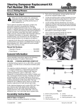
Serial Number Plate
RefertotheFigure1forthelocationof yourserialnumber.
Serial Number Location
Figure 1
Further Assistance
Your dealer wants you to be satisfied with your new
mower.Ifforanyreasonyoudonotunderstandanypartof
this manual or are not satisfied with the service received,
the following actions are suggested:
1. Discuss the matter with your dealership service
managermakingsurehe is awareofanyproblemsyou
mayhaveand that he has had the opportunity to assist
you.
2. If you are still not satisfied, seek out the owner or
general manager of the dealership, explain the
problem and request assistance.
3. For further assistance write or E-mail to:
Land Pride
Service Department
P.O. Box 5060
Salina, KS 674022-5060
E-mail address
lpser[email protected]
IMPORTANT:
For parts and service for your engine contact your
nearest dealer or Call Customer Service Hotline.
Honda Engine Information:
Service Manual: P/N 61ZJ410Z
Owner’s Manual: P/N 31ZJ4620
Service Hotline: 1-770-497-6400
Kawasaki Engine Information:
Service Manual: P/N 99924-2045-02
Owner’s Manual: P/N 99920-2145-02
Service Hotline: 1-800-433-5640
21041
Land Pride welcomes you to the growing family of new
product owners.
This mower has been designed with care and built by
skilled workers using quality materials. Proper assembly,
maintenance, and safe operating practices will help you
get years of satisfactory use from this mower.
Application
The Accu-Z Razor
®
Pro Mowers from Land Pride are
compact in size and ideal for homeowner and light duty
commercial grass maintenance . The Razor Pro is a true
zero-turn mower: When mowing alongside a building or
landscaping, the Razor Pro turns within its own width,
allowingyoutoturnawayandnothitanythingwiththerear
end.Also thesteering leverheights areadjustable making
the mower comfortable to handle.
Using This Manual
• This Operator’s Manual is designed to help familiarize
you with safety, assembly, operation, adjustments,
troubleshooting, and maintenance. Read this manual
entirely prior to operation and follow the recommenda-
tions to help ensure safe and efficient operation.
• The information contained within this manual was
current at the time of printing. Some parts may change
slightly to assure you of the best performance.
• To order anewOperator’sor Parts Manual contactyour
authorized dealer. Manuals can also be downloaded,
free-of-charge from our website at www.landpride.com
or printed by your dealer from the Land Pride Service &
Support Center CD-Rom.
Terminology
“Right” or “Left” as used in this manual is determined by
facing the direction the machine will operate while in use
unless otherwise stated.
Definitions
Owner Assistance
The Warranty Registration card should be filled out by the
dealer at the time of purchase. This information is
necessary to provide you with quality customer service.
If customer service or repair parts are required contact a
Land Pride dealer. A dealer has trained personnel, repair
parts and equipment needed to service the mower.
The parts on your Razor Pro Mower have been specially
designed and should only be replaced with genuine Land
Pride parts. Therefore, should your Razor Pro require
replacement parts go to your Land Pride Dealer.
NOTE: A special point of information that the
operator must be aware of before continuing.
IMPORTANT: A special point of information related to
its preceding topic. Land Pride’s intention is that this
information should be read and noted before
continuing.

7
Section 1 Assembly and Set-Up
7/14/08
ZRP44 & ZRP52 Zero Turning Radius Mowers 356-117M
Land Pride
Table of Contents
Section 1 Assembly and Set-Up
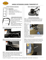
Control Lever & Seat Assembly
Refer to Figure 1-1:
The seat (#1) is shipped loose for ease in shipping. The
control lever’s upper bolts (#4) and nuts (#5) are removed
and the levers are rotated down.
1. Refer to Access to Engine & Hydraulic Pumps on
page 26. The seat platform is hinged at the front. To
raise it, release seat platform latch and tilt the seat
platform up and forward. The seat platform catch will
prevent it from going all the way over.
2. Mount seat (#1) in the operating position, to the seat
platform with four 5/16” nuts (#3) and four 5/16” flat
washers (#2).
3. Connecttheswitchwiresonthemowerwiththeswitch
wires on the seat.
4. Return seat platform to normal operating position.
5. Rotatethe control levers up until the holes line up and
replace the bolts and flat washers as shown.
Control Lever & Seat Assembly
Figure 1-1
21053

8
Section 2 Operating
ZRP44 & ZRP52 Zero Turning Radius Mowers 356-117M 7/14/08
Land Pride
Table of Contents
Section 2 Operating
!
WARNING!
Do not operate mower while smoking!
Controls
Refer to Figure 2-2
For general location of controls described in this section,
refer to Figure 2-1.
Ignition Switch
A three position switch: off, run, and start. With key
inserted, rotate it clockwise to START position; release
key when engine starts, and switch will automatically
return to the RUN position.
Throttle Control
A cable is linked to engine throttle for controlling engine
speed. Move lever forward to increase engine rpm, move
lever rearward to decrease engine rpm.
IMPORTANT: When access is required under the
seat platform, make certain to place the control arms
inthepark brakeposition(out)and pivotthearmrests
upward before placing the seat platform in the full
forward position to prevent arm rest damage.
Razor Pro Controls
Figure 2-1
1. Ignition Switch
2. Throttle Lever
3. Control Levers
4. Blade Engagement Switch
5. Deck Lift Pedal
6. Hour Meter
7. Oil Pressure Light
8. Fuel Tanks
9. Hydraulic reservoir
10. Battery
11. Deck Adjusting Rod
12. Anti-Scalp Wheels
13. Discharge Chute
14. Left Deck Cover
15. Right Deck Cover
16. Deck Height Control
17. Park Brake Switch
18. Choke Lever
21044
1
2
3
4
5
7
8
98
11
12
13
14
15
16
11
12
12
12
10
18
6
12
17
17
Choke Control
A cable is linked to manually operate the engine choke.
When the lever is in the down position, the choke is in the
off(run)position.Whenthelever is pulled up, thechokeis
in the on (start) position. DO NOT operate the machine
with the choke in the on (start) position.
Control Panel
Figure 2-2
Ignition Switch
BladeEngagement
Switch
Oil Pressure
Light
Throttle
Choke
20686

9
Section 2 Operating
7/14/08
ZRP44 & ZRP52 Zero Turning Radius Mowers 356-117M
Land Pride
Table of Contents
Left/Right Fuel Tank Valve
Refer to Figure 2-3:
The mower is equipped with a Left/Right Fuel Tank Valve
located on the right side behind the seat. It determines
which fuel tank the mower is operating from. It is not
important which fuel tank the mower is using.
Left/Right Fuel Tank Switch
Figure 2-3
Blade Engagement Switch
Refer to Figure 2-2:
The Blade engagement switch engages the blade clutch
which engages deck blades. Pull the switch up toengage
and push switch down to disengage the blades.
Control Levers
Refer to Figure 2-4:
Theseleverscontrolthemower’sspeed,direction, neutral
lock and park brake. Levers are used to steer, accelerate,
decelerate, and change direction. The mower will not
move when the engine is on, drive pumps are operating
and the control levers are in the park brake position (out)
(Figure 2-5).
Control Levers
Figure 2-4
The Parking Brakes are applied by moving the control
leversfromtheNeutralPosition(Figure2-4)toan outward
position (Figure 2-5). Each rear wheel brake operates
independently of the other.
!
WARNING!
In the event of a system failure while mowing, engage both
parking brakes to stop or slow mower.
!
WARNING!
The parking brake is not designed to hold the mower on steep
slopes.
Control Levers in Parking Brake Position
Figure 2-5
Deck Lift Pedal
Refer to Figure 2-6:
Thedeckliftpedal is usedtoraiseor lower thedeck.Push
on the pedal to raise the deck and then place the deck
height locking pin into the desired cutting height hole.
Push the deck lift pedal to raise the deck when going over
obstructions.
Deck Lift Pedal
Figure 2-6
IMPORTANT: Never engage blades with engine
running at high rpm or when the deck is under load.
Clutch, belts or deck could be damaged.
Control Levers
21041
20672
Control Levers
Deck Lift
Pedal
20670
Deck Height
Locking Pin

10
Section 2 Operating
ZRP44 & ZRP52 Zero Turning Radius Mowers 356-117M 7/14/08
Land Pride
Table of Contents
Instrumentation
Oil Pressure Light
Refer to Figure 2-2:
This light comes on when the ignition switch is placed in
the RUN position and stays lit until the engine is running
and a safe oil pressure is developed. If light comes on
during operation, shut engine off immediately, locate and
correct the problem.
Electronic Hour Meter
Refer to Figure 2-7
Thehourmeter islocatedon therightside behindtheseat
and registers in 1/10 hour increments up to 9,999.9 total
hours.Connectedtothe ignition switch,themeter records
the accumulative time while the ignition key is switched to
the RUN position and the operator is on the seat.
Electronic Hour Meter
Figure 2-7
Safety Start Interlock System
Themowerisequippedwithasafetystartinterlocksystem
consisting of park brake switches, seat switch and blade
engagement switch.
Check mower safety start interlocksystem each day prior
to operation. This system is an important mower safety
feature and should be repaired immediately if it is
malfunctioning. The mower incorporates a separate seat
switchwhichwill stoptheengine whenever theoperatoris
unseated while the mower is moving or the blades are
engaged. This safety feature is designed to prevent
runaway or accidental entanglement. Inspect the system
as follows:
1. The operator must be on the seat when testing the
seat switch.
2. Set both control levers in the park brake position.
3. Start the engine and allow it to warm up to operating
temperature.
4. A person should be able to slowly raise off the seat
without the engine stopping if the blade engagement
switch is down and the control levers are in the park
brake position.
5. Theengineshouldstopwithintwosecondsifaperson
raises slowly off the seat and either the blade
engagement switch is up or the control levers are in
neutral position.
6. CheckthefunctionoftheseatswitchIfthe enginefails
to stop when the blade engagement switch is up or if
one or both of the control levers are in and the
operator is off the seat. Replace the seat switch If the
seat switch is not operating properly (i.e. switch is not
opening and/or closing).
If the problem cannot be located, contactyour Land Pride
Dealer.
!
WARNING!
The safety interlock system should always function per steps 4
and 5. If it does not function properly, it should be corrected
immediately. Do not operate machine without a properly
functioning seat safety switch.
Engine Starting
The Razor Pro safety start interlock system is also
designed to protect the operator and others from
accidental injury due to unintentional engine starting. The
engine starting motor will not engage until the following
two criteria are meet:
• Control levers are in the brake position.
• Blade engagementswitch isinthedown(OFF)position.
!
WARNING!
The safety interlock system must not be disconnected or
bypassed.
Thefollowingstepsare the correctproceduresfor starting
the engine. If difficulty is encountered, contact the Land
Pride Dealer in your area.
1. Before starting mower each day, perform daily
pre-operationchecking.(See“Safety Start Interlock
System” on this page.)
2. Make sure the control levers are in the brake position
and blade engagement switch is disengaged.
3. Set throttle at approximately 1/2 open position.
4. Insert key in ignition switch and rotate clockwise to
engage starting motor. Release key when engine
starts.
NOTE: The operator’s seat is equipped with a
separatesafetyswitch.Ifforanyreason the operator
should become unseated when the neutral switches
are disengaged or the blade engagement switch is
engaged the engine will stop.
NOTE: Use choke position when engine is cold, or if
warm engine fails to start within 5 seconds of
cranking. Avoid flooding and operate engine without
choking as soon as possible.

11
Section 2 Operating
7/14/08
ZRP44 & ZRP52 Zero Turning Radius Mowers 356-117M
Land Pride
Table of Contents
5. Performtesttomakesuresafetystartinterlocksystem
isoperatingproperly.Referto“Safety Start Interlock
System” on page 10.
6. As soon as engine begins to run, check to make
certain the oil warning light is off. If not, stop engine
immediately and check for the cause. Refer to
“Section 7 Troubleshooting” on page 37.
7. Allow the engine to idle a few minutes before
advancing the throttle and/or engaging the blade
clutch.
8. Beforestopping the engine,place the control leversin
the brakeposition, disengage the blade engagement,
and throttle back to low idle for a couple of minutes;
then rotate ignition key counter-clockwise to the OFF
position. Remove the key from switch before leaving
the seat.
!
WARNING!
Never leave the machine unattended with key in ignition switch.
Moving Mower with Stalled Engine
Refer to Figure 2-7
Themowerhydro-drives are equippedwithbypass valves
for moving the mower when the engine is inoperable. The
valve stems to the bypass valves are located nearthe top
of the hydraulic pumps and are identified as a hex stud.
Before moving the unit, turn each bypass valve stem
counterclockwiseone-halftoonerevolutionandplacethe
control levers in neutral position.
Donottow the machine.Moveit by handoruse awinchto
load it on a trailer for transporting.
When transporting on another vehicle, the tractor should
be facing forward and it must be secured.
Bypass Valve
Figure 2-7
Driving the Mower
!
DANGER!
Never make sudden stops or sudden reversing of direction,
especially when going down a slope. The steering is designed
for sensitive response. Rapid movement of the control levers in
either direction could result in a reaction of the mower that can
cause serious injury.
Steering
Refer to Figure 2-8 on page 12
After starting engine, engage the control levers and steer
as follows:
• To Go Forward:
Push control levers forward an equal distance.
• To Go in Reverse:
Pull control levers rearward an equal distance.
• To Turn Left:
Move the right control lever farther forward from neutral
than the left control lever.
• To Turn Right:
Move the left control lever farther forward from neutral
than the right control lever.
• To Pivot Turn:
Move onecontrol lever forwardandthe other controllever
back of neutral, this will allow the drive wheels to counter-
rotate.
Controlling the Speed
!
WARNING!
In the event of a system failure while mowing, engage both
parking brakes to stop or slow mower. Refer to Figure 2-5.
!
DANGER!
When going in reverse push forward gently on control levers
and avoid sudden movement. Any sudden movement could
cause the front of the mower to come off of the ground resulting
in possible loss of control.
To Stop or decrease speed:
Move control levers to neutral. When going forward pull
backgentlyon controllevers. Whengoing in reversepush
forward gently on control levers.
To Increase Speed:
Increase control levers equal distance from neutral. The
farther forward control levers are from neutral, the faster
the mower will travel forward. The fartherback thecontrol
levers are from neutral, the faster the mower will go in
reverse.
IMPORTANT: The engine starter should not be
operatedforperiodslongerthen30secondsatatime.
An interval of at least two minutes should be allowed
between such cranking periods to protect the starter
from overheating and burn-out.
21054
Bypass valve
IMPORTANT: Following repairs, always make certain
the two bypass valve stems are returned to their
operating position before running the mower.

12
Section 2 Operating
ZRP44 & ZRP52 Zero Turning Radius Mowers 356-117M 7/14/08
Land Pride
Table of Contents
Operating Suggestions
!
DANGER!
Priortooperatingthemowerthe operatorshouldbe thoroughly
familiar with the proper use and operation of the equipment,
should read the manual completely and thoroughly, and should
haveattemptedslowmovingmaneuversto becomefamiliarwith
the operation of the equipment before attempting normal speed
operation.Aninexperiencedoperatorshould not mow on slopes
or on uneven terrain.
!
WARNING!
The mower’s control levers are very responsive: Easy does it!
For smooth operation, move lever slowly, avoid sudden
movement. Skill and ease of operation come with practice and
experience.
Inexperienced operators may have a tendency to
over-steer and lose control. Slow-moving practice
maneuvers are recommended to become familiar with
these characteristics before attempting normal speed
operation.
!
WARNING!
Sharpdepressionsorraisedobstacles(suchasguttersorcurbs)
should not be directly approached at high speed in an attempt
to jump them as the operator could be thrown from the mower.
Approach at a slow speed and angle one drive wheel at the
obstruction. Continue at an angle until the wheel clears and
then pivot the opposite wheel around.
When turning on soft wet turf, keep both wheels rolling
either forward or backward. Pivoting on one stopped
wheel can damage turf. Thisis especially important when
mowing.
Peakmowingperformanceismaintainedwhenthethrottle
is set at full rpm. This gives maximum power to the drive
wheels and deck when needed. Use the control levers to
control ground speed rather than engine rpm.
!
WARNING!
Do not operate the equipment while wearing sandals, tennis
shoes, sneakers, shorts or any type of loose fitting clothing.
Always wear long pants, safety glasses and safety shoes when
operating this machine.
Keepbladessharp. Manyproblemswithincorrectcutting
patterns are due todullbladesorbladeswhichhavebeen
sharpened incorrectly. Information on sharpening blades
is listed in this manual’s maintenance section. In addition,
most communities have individuals or companies which
specialize in sharpening mower blades. Blade sharpness
should be checked daily.
Often professional mowing companies have an additional
set of blades and change blades twice a day: once in the
morning and again at noon.
Use high blade speed. Your Razor Pro is designed to
operate at full throttle. The throttle setting directly controls
bladespeed.The highest blade speedgenerallygives the
best cut.
Directgrassdischargeawayfromunmownarea.Refer
to Figure 2-9 on page 13. Select a mowing pattern that
directsgrassdischargeawayfromuncutgrass.Generally,
this means using a pattern utilizing left turns because
grasssidedischargeistotheright. Grassdischargedonto
an unmowed area will be mowed twice. Mowing grass
twice puts an unnecessary load on the mower and
reduces mowing efficiency.
Steering
Figure 2-8
Front of Mower Faces This Direction
N
N
Forward Travel Pivot Right Turn Forward Travel
Right Turn
Reverse Travel
Right Turn
Reverse Travel
N= Neutral Position
Direction of arrows indicate direction of mower movement.

13
Section 2 Operating
7/14/08
ZRP44 & ZRP52 Zero Turning Radius Mowers 356-117M
Land Pride
Table of Contents
Discharge Chute
Figure 2-9
!
WARNING!
Never direct discharge of material from mower deck towards
bystanders.
!
WARNING!
Never operate the mower deck with discharge chute removed or
in raised position.
!
WARNING!
Always check area to be mowed for rocks and other debris
before mowing.
Mower Deck Operation
!
DANGER!
Neverattemptto make any adjustmentsto the mower deckwhile
the engine is running or when the blades are engaged. Mower
blades cannot be seen and are located very close to deck
housing. Fingers and toes can be cut off instantly.
With the engine running, engage the blades (Refer to
Figure 2-10) and advance engine throttle to full rpm.
Blade Engagement Switch
Figure 2-10
Operating Instructions
After thoroughly familiarizing yourself with the Operator’s
Manual and completing the Operator’s Checklist, you are
almost ready to begin mowing.
Approach the mower from the front. Spread the steering
levers fully apart if they aren’t already in the wide-open
parking brake position. Taking care not to step on either
sideofthemowerdeck, stepupontheoperators’ platform
and comfortably seat yourself. With both steering levers
stillwide apartnow reachfor thethrottle andchoke control
to your right side. Position the throttle control at half
throttle and pull the choke to the “up/on” position. Insert
yourignitionkeyand rotate the ignitionkeyclockwiseuntil
you hear the engine begin to start. Release the ignition
key and push the choke to “down/off” position. Allow the
engine to warm up momentarily. If your mower has just
been running and the engine is already warm, using the
choke is usually not necessary.
With the engine at half throttle reach forward and bring
both steering levers equally together in the neutral
position just in front of you. It’s now time to test your
steering skills. Gently push both steering levers equally
forward.Thefartherforwardyoupushtheleversthefaster
you will go. Pull back equally and you will slow down
comingtoastopwhenyoureachtheneutralposition.Now
slowly pull the levers back toward your body past neutral
position. The mower will reverse direction and increase in
speed as you pull further back. If you push one lever
forward and pull one lever back the mower will do a Zero
turn in the direction of the steering lever closest to your
body. Now take a few moments in a safe area to practice
steering your mower with the engine still at half throttle.
Graduallyincrease yourthrottle speeduntil youfeel totally
confident in your mower steering and handling ability.
It’s now time to cut the grass. Hopefully you have already
removedany obstaclesfrom thelawn thatyou donot want
run over. With your mower at half throttle, placeyour right
foot on the deck lift pedal and release and lower the deck
to your preset cutting height. With your right hand, pull up
on the cutting blade engagement knob and increase the
engine speed to full throttle. You may now begin mowing.
When you are done mowing or just want to take a break,
make sure you do all of the following. Park on level
ground, disengage the cutting blade, throttle back, leave
the steering levers in wide-open parking brake position,
turn the engine off, remove the key, and step carefully off
the front of the machine.
Discharge
Chute
21043
NOTE: Engaging the blades at high engine rpm or
when under heavy load (in tall grass for example)
can cause belts to slip, resulting in premature wear
or possible damage.
Blade Engagement
Switch
21043

14
Section 3 Adjustments
ZRP44 & ZRP52 Zero Turning Radius Mowers 356-117M 7/14/08
Land Pride
Table of Contents
Section 3 Adjustments
Introduction
!
WARNING!
Unless specifically required, DO NOT have engine running
when servicing or making adjustments to the mower. Place
control levers in the park brake position and remove ignition
switch key. Repairs or maintenance requiring engine power
should be performed by trained personnel only. To prevent
carbon monoxide poisoning, be sure proper ventilation is
available when engine must be operated in an enclosed area.
Read and observe safety warnings in front of manual.
Your Razor Prowas adjusted before it left the factory and
was checked during pre-delivery set-up. However, after
start-up and continued use, a certain amount of break-in
wear will cause some adjustments to change.
Remainalertforunusual noises, they couldbesignalinga
problem. Visually inspect the machine for any abnormal
wearordamage. Agoodtime todetectpotential problems
is while performing scheduled maintenance service.
Correcting the problem as quickly as possible is the best
insurance.
!
WARNING!
Keep your machine clean and remove heavy deposits of trash
and clippings. They can cause engine fires and hydraulic
overheating as well as excessive belt wear.
Clear away heavy build-up of grease, oil and dirt,
especially in the area of oil, fuel and engine combustion
air; minute dust particles are abrasive to close-tolerance
engine and hydraulic assemblies.
Some repairs require the assistance of a trained service
mechanic and should not be attempted by unskilled
personnel. Consult your Land Pride service center when
assistance is needed.
Torque Values
!
WARNING!
Particular attention must be given to tightening the drive wheel
lug nuts and blade spindle bolts. Failure to correctly torque
these items may result in the loss of a wheel or blade, which can
cause serious damage or personal injury.
It is recommended that the following be checked after the
first 2 hours of initial operation, and every 50 hours
following removal for repair or replacement:
• Wheel lug nuts
• Wheel motor nut
• Blade spindle bolts (top and bottom)
• For engine torque values, see engine owner’s manual.
• For all other torques refer to Torque Values Chart for
Common Bolt Sizes on page 39.
Steering Linkage
Refer to Figure 3-1
Theneutraladjustmentfor the control leversintheneutral
position is discussed in this section.
The steering has been factory adjusted to eliminate
creeping when the control levers are in neutral position.
However, should the mower begin to creep, adjustments
can be made as outlined on the following page.
Control Lever In Neutral Position
Figure 3-1
Torque Values
FT - lbs. N-m
Wheel lug nuts 65 - 75 88.14 - 101.7
Wheel motor nut 290-310 393.2 - 420.4
Blade spindle bolts (top
and bottom)
118 160.01
Control
Lever
Park Brake Slot
21043

15
Section 3 Adjustments
7/14/08
ZRP44 & ZRP52 Zero Turning Radius Mowers 356-117M
Land Pride
Table of Contents
Control Lever Neutral Adjustment
Refer to Figure 3-2
Before considering any adjustment, check the tire air
pressure and make certain hydraulic system oil is at
operating temperature. Unequal tire pressure will cause
the mower to drift to one side. Refer to “Tire Inflation
Chart” on page 19 and page 39.
Fine adjustment to the steering is made with the
adjustablepumplinkage rods locatedbetweenthe control
lever and pump arms.
Steering Control Linkage
Figure 3-2
Neutral is properly adjusted when the control levers are in
the neutral position and the drive wheels are not turning.
If the mower creeps in the neutral position the control
linkage may be adjusted as follows:
1. Raiseand blockthe mowerup sothedrivewheelsare
off of the floor.
!
WARNING!
Make certain mower is secure when it is raised and placed on
the jack stands. The jack stands should not allow the mower to
move when the engine is running and the drive wheels are
rotating. Use only certified jack stands.
2. Position the control levers in the neutral position.
Disengage the blades.
3. Start the engine and observe which way the wheels
are rotating.
4. Ifwheel(s)arerotatingforward,loosenthejamnutson
the pump linkage rods and rotate the rod to lengthen
the steering control linkage until the wheel(s) come to
a stop. Repeat for the opposite side if necessary.
5. If wheel(s) are rotating in reverse then loosen the jam
nuts on the pump linkage rods and rotate the rod to
shorten the steering control linkage until the wheel(s)
come to a stop. Repeat for the opposite side if
necessary.
6. When both wheels remain in neutral, tighten the jam
nuts to lock the turnbuckle in place.
7. Test again by moving the control levers forward and
backward before returning them to the neutral
position.Ifthetiresareinneutral,theunitisnowready
for operation.
8. After adjusting for neutral it may be necessary to
readjust the steering dampener and/or the control
lever stop. Fig. 5-3 or Fig. 5-4
Control lever stops
Refer to Figure 3-3
The control lever stops are designed to do two things:
First,andmostimportant, they must keepthepumpsfrom
bottoming out internally. Secondly, the stops may be
adjusted to help drive straight when the control levers are
pushed forward against the stops.
Figure 3-3
To keep the pumps from bottoming out internally use the
following procedure:
1. To make the first adjustment the tractor engine must
NOT be running.
2. Check to make sure the control levers are against the
stopsbeforethepumpsarebottomedoutinternally.To
do this, gently and slowly move the control levers
forward and feel if there is some resistance on the
pump lever before the control levers hit the stops.
Check one side at a time. If you sense that the pump
arms are stopping the forward motion of the control
arms, loosen the jam nuton the adjustablestopofthe
corresponding side and turn the stop (set screw)
inward to stop the control levers slightly before the
pumpbottoms out.Lockin placewhen theadjustment
is correct by re-tightening the jam nut.
Jam Nut
Pump Linkage Rod
20684
NOTE: The left linkage controls the right hydraulic
pump and the right linkage controls the left hydraulic
pump.
Jam Nut
Stop
Control Lever
21067

16
Section 3 Adjustments
ZRP44 & ZRP52 Zero Turning Radius Mowers 356-117M 7/14/08
Land Pride
Table of Contents
3. Do this for each side.
Refer to Figure 3-3 on page 15. To adjust the stops for
driving straight when control levers are against the stops
during operation:
4. Determine which drive tire is rotating too fast when
both control levers are against the stops. Then stop
thetractorandloosenthe locknut ontheside whichis
rotatingtoofastandturnthestop(setscrew)inwardto
stop the control lever sooner. Tighten the lock nut on
the stop and test again. Repeat this procedure until
unit drives straight.
Steering Dampener
Refer to Figure 3-4:
The steering dampeners, one for each control lever, are
spring loaded to return the control levers to neutral
position from reverse position. This gives the operator a
sense of neutral during operation. Set the steering
dampeners in the correct operating position as follows:
1. Place control lever in the neutral position.
2. Loosen steering dampener’s front ball stud.
3. Pull the dampener spring housing, to the front, past
the point that the internal spring is engaged.
4. Release the dampener spring housing and allow the
internalspringtobringthe housing backto theneutral
position.
5. Tighten the nut on the steering dampener’s front ball
stud.
6. To check, move the control lever to the reverse
position and release. The control lever should return
to the neutral position. If not, repeat steps 1 through 6.
Steering Dampener
Figure 3-4
Control Lever Adjustment
Refer to Figure 3-5
The control levers may be adjusted vertically and pivoted
forward or backward for operator comfort. Adjust the
control levers vertically by removing the capscrews, flat
washers,andlocknuts that attach theuppercontrol levers
to the lower control levers. Reposition the upper control
levers to a height that fits the operator’s personal
preference.Reassemblethecapscrews,flatwashers,and
locknuts in the same order they were removed without
tightening them. Pivot the upper control levers forward or
backward to again fit the operator’s personal preference.
Verify that the control levers align with each other when in
the neutral position and tighten the locknuts to correct
torque.
Control Lever Adjustment*
Figure 3-5
Park Brake Adjustment
Occasionallycheckthe park brakesandadjustment using
the following method:
1. Position the control levers in the neutral position.
Disengage the deck clutch.
!
WARNING!
Make certain machine is secure when it is raised and placed on
the jack stands. Thejackstands should not allow themachineto
move when the engine is running and the drive wheels are
rotating. Use only certified jack stands.
NOTE: Since this is a hydrostatic drive, variables
such as temperature of oil, efficiency of pumps and
motors, tire pressure etc.may effectthe consistency
of the ability to rely on the stops to drive straight
without the operator making minor steering
adjustments with the control arms.
21068
Dampener Spring Housing
Front Ball Stud
NOTE: Thedampenermustnot bottomout whenthe
pump lever is fully stroked in either direction.
21067
Capscrews with
Flat Washers
LowerControl
Lever
Upper
Control
Lever
*Actual body and frame colors may be different than what is represented in the picture.

17
Section 3 Adjustments
7/14/08
ZRP44 & ZRP52 Zero Turning Radius Mowers 356-117M
Land Pride
Table of Contents
Figure 3-6
2. Raiseand blockthetractorupsothedrivewheelsare
off of the floor.
3. RefertoFigure3-7.Openthehydraulicpumpsbypass
valve, on the side that is being adjusted, by turning
bypass valve counter clockwise one-half to one
revolution. The valve stems on each hydraulic pump
are located near the top and are identified as a hex
stud.
Figure 3-7
4. Rotate the tire. The tire should rotate. Remember
hydraulic oil resistance will prevent the tire from
rotating freely even with the bypass valves open.
There should be no resistancefrom the brakes at this
point.
5. Refer to Figure 3-8. Move the control lever to where it
is just inside (1/8”) the park brake slot.
Control Lever Position*
Figure 3-8
Control Lever Position*
Figure 3-9
6. Rotatethetire.Ifthebrakeisadjustedproperlythetire
will still rotate but friction will start to become
noticeable here. However, if no brake resistance is
noticed, the brake needs adjusted as follows:
NOTE:RefertoFigure3-6.The front brakelinkis not
adjustable.
Front brake link
(right side)
21058
21054
Bypass valve
1/8”
Park Brake
Slot
Control Lever
21070
NOTE: Refer to Figure 3-9. When the control lever is
against the outside edge of the slot, the brakes
should not be engaged.
Park Brake
Slot
Outside Edge
Control Lever
Travel Slot
21071
*Actual body and frame colors may be different than what is represented in the picture.

18
Section 3 Adjustments
ZRP44 & ZRP52 Zero Turning Radius Mowers 356-117M 7/14/08
Land Pride
Table of Contents
7. Refer to Figure 3-10. Loosen the brake linkage jam
nuts.
Figure 3-10
8. Rotate the tire and at the same time rotate the
turnbuckletoshortenthelengthofthebrakelinkageto
increase the brakepressure. When youfeelthebrake
begin to engage, stop adjusting the turnbuckle.
Retighten the jam nuts on the turnbuckle.
9. Refer to Figure 3-11. Place the control lever in the
park brake slot. The tire should not rotate when the
control lever is in the park brake position.
Control Lever Position*
Figure 3-11
10. Place the control lever in the neutral position. The tire
should rotate freely.
11. Close the hydraulic pumps bypass valve.
12. Repeat steps 3 thru 11 for the other side.
13. Remove the jack stands and lower the unit. It is now
ready to operate.
Hydro-Drive Belt Adjustment
Refer to Figure 3-12
The pump drive belt tension remains constant by means
of a tension idler and spring. There is no tension
adjustment of this belt.
Figure 3-12
Deck Drive Belt Adjustment
Refer to Figure 3-13:
The spindle belt tension remains constant by means of a
tension idler and spring. The spring tension should be
such that the belt does not slip under normal operating
loadconditions,assumingthe belt isnotexcessively worn
or damaged. As belt stretches and wears in, adjustment
may become necessary. To increase belt tension, move
the spring chain one (or more) link(s) at the anchor
bracket.Installed spring length should be 9.0" +/- .3"
(22.8 cm +/- .76 cm) originally with adjustments of .60"
(15.2 mm) per chain link.
Drive Belt Adjustment
Figure 3-13
21073
Turnbuckle
Jam Nut
Brake Linkage
Jam Nut
Control Lever in Park Brake Position
21089
Spring
Tension Idler
Pump Drive
Belt
21090
Chain
Anchor Bracket
Tension
Idler
Spring
19929
*Actual body and frame colors may be different than what is represented in the picture.
/