Page is loading ...

Installation, use and maintenance instructions
20160907 (2) - 11/2020
Dual fuel light oil/ gas burners
Two stage progressive or modulating operation
CODE MODEL TYPE
20163249 GI/EMME 1400 680T1
20163312 GI/EMME 2000 681T1
20163313 GI/EMME 2000 681T1
20163264 GI/EMME 2000 681T1
20160903 GI/EMME 3000 682T1
20162382 GI/EMME 3000 682T1
20162388 GI/EMME 3000 682T1
20162385 GI/EMME 3000 682T1
20162391 GI/EMME 3000 682T1
20160912 GI/EMME 4500 683T1
GB

Translation of the original instructions

1 20160907
GB
Contents
1 Declarations................................................................................................................................................................................ 3
2 Information and general warnings............................................................................................................................................ 4
2.1 Information about the instruction manual .................................................................................................................... 4
2.2 Guarantee and responsibility....................................................................................................................................... 5
3 Safety and prevention................................................................................................................................................................ 6
3.1 Introduction.................................................................................................................................................................. 6
3.2 Personnel training ....................................................................................................................................................... 6
4 Technical description of the burner ......................................................................................................................................... 7
4.1 Burner designation ...................................................................................................................................................... 7
4.2 Models available.......................................................................................................................................................... 7
4.3 Burner categories - Countries of destination ............................................................................................................... 8
4.4 Technical data............................................................................................................................................................. 8
4.5 Electrical data.............................................................................................................................................................. 9
4.6 Maximum dimensions.................................................................................................................................................. 9
4.7 Firing rates ................................................................................................................................................................ 10
4.8 Test boiler.................................................................................................................................................................. 10
4.9 Burner description ..................................................................................................................................................... 11
4.10 Electrical panel description........................................................................................................................................ 12
4.11 Burner equipment...................................................................................................................................................... 12
4.12 Control box RFGO-A22............................................................................................................................................. 13
4.13 Servomotor SQM40 .................................................................................................................................................. 14
5 Installation ................................................................................................................................................................................ 15
5.1 Notes on safety for the installation ............................................................................................................................ 15
5.2 Handling .................................................................................................................................................................... 15
5.3 Preliminary checks .................................................................................................................................................... 15
5.4 Operating position ..................................................................................................................................................... 16
5.5 Preparing the boiler................................................................................................................................................... 16
5.6 Lifting points .............................................................................................................................................................. 17
5.7 Positioning the electrode........................................................................................................................................... 17
5.8 Air damper setting ..................................................................................................................................................... 17
5.9 Nozzle installation ..................................................................................................................................................... 18
5.10 Combustion head adjustment.................................................................................................................................... 19
5.11 Light oil supply........................................................................................................................................................... 20
5.12 Hydraulic operation diagram ..................................................................................................................................... 21
5.13 Pressure variator....................................................................................................................................................... 21
5.14 Pump......................................................................................................................................................................... 22
5.15 Gas supply ................................................................................................................................................................ 23
5.16 Electrical connections................................................................................................................................................ 26
5.17 Calibration of the thermal relay ................................................................................................................................. 27
5.18 Motor rotation ............................................................................................................................................................ 27
6 Start-up, calibration and operation of the burner ................................................................................................................. 28
6.1 Notes on safety for the first start-up .......................................................................................................................... 28
6.2 Adjustments prior to ignition (light oil) ....................................................................................................................... 28
6.3 Burner ignition (light oil)............................................................................................................................................. 28
6.4 Adjustments prior to ignition (gas)............................................................................................................................. 29
6.5 Burner start-up (gas) ................................................................................................................................................. 29
6.6 Burner ignition ........................................................................................................................................................... 29
6.7 Servomotor adjustment ............................................................................................................................................. 30

20160907 2
GB
Contents
6.8 Combustion air adjustment ........................................................................................................................................31
6.9 Ignition output of the burner .......................................................................................................................................32
6.10 Air / fuel adjustment ...................................................................................................................................................32
6.11 Pressure switch adjustment .......................................................................................................................................34
6.12 Burner operation ........................................................................................................................................................36
6.13 Final checks (with burner operating)..........................................................................................................................37
7 Maintenance ..............................................................................................................................................................................38
7.1 Notes on safety for the maintenance .........................................................................................................................38
7.2 Maintenance programme ...........................................................................................................................................38
7.3 Opening the burner ....................................................................................................................................................41
7.4 Closing the burner......................................................................................................................................................41
8 LED indicator and special function.........................................................................................................................................42
8.1 Description of LED lamps ..........................................................................................................................................42
8.2 Check mode function .................................................................................................................................................42
8.3 Flame control lock-out or emergency stop condition .................................................................................................42
8.4 LED lamps: burner operating status ..........................................................................................................................43
9 Problems - Causes - Remedies signalled by LED indicators ...............................................................................................44
A Appendix - Accessories ...........................................................................................................................................................49
B Appendix - Electrical panel layout...........................................................................................................................................50

3 20160907
GB
Declarations
1 Declarations
Declaration of Conformity in accordance with ISO / IEC 17050-1
Manufacturer: RIELLO S.p.A.
Address: Via Pilade Riello, 7
37045 Legnago (VR)
Product: Dual fuel light oil/gas burners
Model and type: GI/EMME 1400
GI/EMME 2000
GI/EMME 3000
GI/EMME 4500
680T1
681T1
682T1
683T1
These products are in compliance with the following Technical Standards:
EN 676
EN 267
EN 12100
and according to the European Directives:
GAR 2016/426/EU Gas Devices Regulation
MD 2006/42/EC Machine Directive
LVD 2014/35/EU Low Voltage Directive
EMC 2014/30/EU Electromagnetic Compatibility
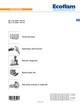
Such products are marked as indicated below:
The quality is guaranteed by a quality and management system certified in accordance with ISO 9001:2015.
Legnago, 21.04.2018 General Manager
RIELLO S.p.A. - Burners Department
Research and Development Director
RIELLO S.p.A. - Burners Department
Eng. U. Ferretti Eng. F. Comencini
CE-0085AQ0712 Class 1 (EN 267) - Class 1 (EN 676)

20160907 4
GB
Information and general warnings
2.1 Information about the instruction manual
2.1.1 Introduction
The instruction manual supplied with the burner:
is an integral and essential part of the product and must not
be separated from it; it must therefore be kept carefully for
any necessary consultation and must accompany the burner
even if it is transferred to another owner or user, or to
another system. If the manual is lost or damaged, another
copy must be requested from the Technical Assistance
Centre of the area;
is designed for use by qualified personnel;
offers important indications and instructions relating to the
installation safety, start-up, use and maintenance of the
burner.
Symbols used in the manual
In some parts of the manual you will see triangular DANGER
signs. Pay great attention to these, as they indicate a situation of
potential danger.
2.1.2 General dangers
The dangers can be of 3 levels, as indicated below.
2.1.3 Other symbols
Abbreviations used
Ch. Chapter
Fig. Figure
Page Page
Sec. Section
Tab. Table
2 Information and general warnings
DANGER
Maximum danger level!
This symbol indicates operations which, if not
carried out correctly, cause serious injury, death
or long-term health risks.
ATTENTION
This symbol indicates operations which, if not
carried out correctly, may cause serious injury,
death or long-term health risks.
CAUTION
This symbol indicates operations which, if not
carried out correctly, may cause damage to the
machine and/or injury to people.
DANGER
DANGER: LIVE COMPONENTS
This symbol indicates operations which, if not
carried out correctly, lead to electric shocks with
lethal consequences.
DANGER: FLAMMABLE MATERIAL
This symbol indicates the presence of flammable
materials.
DANGER: BURNING
This symbol indicates the risks of burns due to
high temperatures.
DANGER: CRUSHING OF LIMBS
This symbol indicates the presence of moving
parts: danger of crushing of limbs.
WARNING: MOVING PARTS
This symbol indicates that you must keep limbs
away from moving mechanical parts; danger of
crushing.
DANGER: EXPLOSION
This symbol signals places where an explosive
atmosphere may be present. An explosive
atmosphere is defined as a mixture - under
atmospheric conditions - of air and flammable
substances in the form of gases, vapours, mist or
dust in which, after ignition has occurred,
combustion spreads to the entire unburned
mixture.
PERSONAL PROTECTION EQUIPMENT
These symbols indicate the equipment that must
be worn and kept by the operator for protection
against threats against safety and/or health while
at work.
OBLIGATION TO ASSEMBLE THE COVER
AND ALL THE SAFETY AND PROTECTION
DEVICES
This symbol signals the obligation to reassemble
the cover and all the safety and protection devices
of the burner after any maintenance, cleaning or
checking operations.
ENVIRONMENTAL PROTECTION
This symbol gives indications for the use of the
machine with respect for the environment.
IMPORTANT INFORMATION
This symbol indicates important information that
you must bear in mind.
This symbol indicates a list.

5 20160907
GB
Information and general warnings
2.1.4 Delivery of the system and the instruction
manual
When the system is delivered, it is important that:
the instruction manual is delivered to the user by the system
manufacturer, with the recommendation to keep it in the
room where the heat generator is to be installed.
The instruction manual shows:
– the serial number of the burner;
– the address and telephone number of the nearest
Assistance Centre;
The system supplier must carefully inform the user about:
– the use of the system;
– any further tests that may be required before activating the
system;
– maintenance, and the need to have the system checked at
least once a year by a representative of the manufacturer
or another specialised technician.
To ensure a periodic check, the manufacturer
recommends the drawing up of a Maintenance Contract.
2.2 Guarantee and responsibility
The manufacturer guarantees its new products from the date of
installation, in accordance with the regulations in force and/or the
sales contract. At the moment of the first start-up, check that the
burner is integral and complete.
In particular, the rights to the guarantee and the responsibility will
no longer be valid, in the event of damage to things or injury to
people, if such damage/injury was due to any of the following
causes:
incorrect installation, start-up, use and maintenance of the
burner;
improper, incorrect or unreasonable use of the burner;
intervention of unqualified personnel;
carrying out of unauthorised modifications on the equipment;
use of the burner with safety devices that are faulty,
incorrectly applied and/or not working;
installation of untested supplementary components on the
burner;
powering of the burner with unsuitable fuels;
faults in the fuel supply system;
continuation of use of the burner when a fault has occurred;
repairs and/or overhauls incorrectly carried out;
modification of the combustion chamber with inserts that
prevent the regular development of the structurally
established flame;
insufficient and inappropriate surveillance and care of those
burner components most likely to be subject to wear and
tear;
use of non-original components, including spare parts, kits,
accessories and optional;
force majeure.
The manufacturer furthermore declines any and every
responsibility for the failure to observe the contents of this
manual.
.........................................................................................
.........................................................................................
.........................................................................................
.........................................................................................
ATTENTION
Failure to observe the information given in this
manual, operating negligence, incorrect
installation and carrying out of non authorised
modifications will result in the annulment by the
manufacturer of the guarantee that it supplies with
the burner.

20160907 6
GB
Safety and prevention
3.1 Introduction
The burners have been designed and built in compliance with
current regulations and directives, applying the known technical
safety rules and envisaging all the potential danger situations.
It is necessary, however, to bear in mind that the imprudent and
clumsy use of the equipment may lead to situations of death risk
for the user or third parties, as well as the damaging of the burner
or other items. Inattention, thoughtlessness and excessive
confidence often cause accidents; the same applies to tiredness
and sleepiness.
It is a good idea to remember the following:
The burner must only be used as expressly described. Any
other use should be considered improper and therefore
dangerous.
Specifically:
it can be applied to boilers operating with water, steam,
diathermic oil, and to other uses expressly named by the
manufacturer;
the type and pressure of the fuel, the voltage and frequency of the
electrical power supply, the minimum and maximum deliveries for
which the burner has been regulated, the pressurisation of the
combustion chamber, the dimensions of the combustion
chamber and the ambient temperature must all be within the
values indicated in the instruction manual.
Modification of the burner to alter its performance and
destinations is not allowed.
The burner must be used in exemplary technical safety
conditions. Any disturbances that could compromise safety
must be quickly eliminated.
Opening or tampering with the burner components is not
allowed, apart from the parts requiring maintenance.
Only those parts envisaged by the manufacturer can be
replaced.
3.2 Personnel training
The user is the person, body or company that has acquired the
machine and intends to use it for the specific purpose. He is
responsible for the machine and for the training of the people
working around it.
The user:
undertakes to entrust the machine exclusively to suitably
trained and qualified personnel;
undertakes to inform his personnel in a suitable way about
the application and observance of the safety instructions.
With that aim, he undertakes to ensure that everyone knows
the use and safety instructions for his own duties;
Personnel must observe all the danger and caution
indications shown on the machine.
Personnel must not carry out, on their own initiative,
operations or interventions that are not within their province.
Personnel must inform their superiors of every problem or
dangerous situation that may arise.
The assembly of parts of other makes, or any modifications,
can alter the characteristics of the machine and hence
compromise operating safety. The manufacturer therefore
declines any and every responsibility for any damage that
may be caused by the use of non-original parts.
In addition:
3 Safety and prevention
ATTENTION
The manufacturer guarantees safety and proper
operation only if all burner components are intact
and correctly positioned.
must take all the measures necessary to
prevent unauthorised people gaining access
to the machine;
the user must inform the manufacturer if
faults or malfunctioning of the accident
prevention systems are noticed, along with
any presumed danger situation;
personnel must always use the personal
protective equipment envisaged by legislation
and follow the indications given in this
manual.

7 20160907
GB
Technical description of the burner
4.1 Burner designation
4.2 Models available
Tab. A
4 Technical description of the burner
Designation Voltage Start-up Code
GI/EMME 1400 TC FS1 3 230/400/50 Direct 20163249
GI/EMME 2000 TC FS1 3 230/400/50 Direct 20163312
GI/EMME 2000 TC FS1 3 230/400/50 Direct 20163313
GI/EMME 2000 TC FS1 3N 400/50 Star/Triangle 20163264
GI/EMME 3000 TC FS1 3 400/50 Direct 20160903
GI/EMME 3000 TC FS1 3 400/50 Direct 20162382
GI/EMME 3000 TC FS1 3N 400/50 Star/Triangle 20162388
GI/EMME 3000 TC FS1 3 230/50 Direct 20162385
GI/EMME 3000 TC FS1 3 230/50 Direct 20162391
GI/EMME 4500 TC FS1 3N 400/50 Star/Triangle 20160912
Continuous operation only with the use of a flame detection
electrode (ionisation)
Class 2 EN267 - Class 3 EN676
Series: GI/EMME
Size
Fuel:
Natural gas
Light oil
Adjustment:
Electrical supply of the system:
3/400/50
3/230/50
Voltage of auxiliaries:
230/50
110/50/60
GI/EMME 2000 TC
Emission: C11 or... Class 1 EN267 - EN676
C22 or MZ Class 2 EN267 - EN676
C33 or BLU Class 3 EN267 - EN676
FS1 3/400/50 230/50/60
BASIC DESIGNATION
EXTENDED DESIGNATION
3N / 400V / 50Hz
3N / 230V / 50Hz
230V / 50Hz
110V / 50-60Hz
Heavy oil
E Electronic cam
EV Electronic cam and variable speed (with Inverter)
P Proportional air/gas valve
BP Two stage (light oil) / Proportional valve (gas)
M Mechanical cam
M
G
N
Head: TC Standard head
TL Extended head
C23 or MX
C13 Class 1 EN267 - Class 3 EN676
Flame control system:
Standard (1 stop every 24 h)
FS2
FS1
MC11

20160907 8
GB
Technical description of the burner
4.3 Burner categories - Countries of destination
Tab. B
4.4 Technical data
Tab. C
(1) Reference conditions: Ambient temperature 20°C - Gas temperature 15°C - Barometric pressure 1013 mbar - Altitude 0 m a.s.l.
(3) Sound pressure measured in manufacturer's combustion laboratory, with burner operating on test boiler and at maximum output. The sound power
is measured using the "Free Field" method, required by EN 15036 standard, and according to an “Accuracy: Category 3” measurement, as
described in EN ISO 3746.
Country of destination Gas category
SE - FI - AT - GR - DK - ES - GB - IT - IE - PT - IS - CH - NO I2H
DE I2ELL
NL I2L - I2E - I2 (43.46 ÷ 45.3 MJ/m3 (0°C))
FR I2Er
BE I2E(R)B
LU - PL I2E
Model GI/EMME 1400 GI/EMME 2000 GI/EMME 3000 GI/EMME 4500
Type 680 T1 681 T1 682 T1 683 T1
Minimum Modulation
Output
Kcal/h 350,000 500,000 750,000 1,000,000
kW 407 581 872 1,163
Minimum operating
output
Kcal/h 705,000 1,000,000 1,500,000 2,021,000
kW 820 1,163 1,744 2,350
Maximum operating
output
Kcal/h 1,325,000 2,000,000 3,000,000 4,000,000
kW 1,540 2,325 3,488 4,650
Fuel Methane gas: 8 - 10 kWh/Nm3
Light oil: max. viscosity at 20 °C 6 cSt (1.5°E)
Maximum gas pressure mbar 200 360 360 360
Minimum gas pressure (1) mbar 20 26 33 43
Operation – Intermittent (min. 1 stop in 24 hours)
– Progressive two-stage or modulating by kit (see accessories)
Pump: type TA2C TA3C TA4C TA5C
- Output at 400 bar kg/h 350 540 730 1000
- Pressure range bar 7 - 40 7 - 40 7 - 40 7 - 30
Standard applications Boilers: water, steam, diathermic oil
Ambient temperature °C 0 - 50
Combustion air temperature °C max 60
Noise levels (2) Sound pressure
Sound power
dB(A) 75
85
78
88
82
92
84
94
Weight Kg 190 235 280 285

9 20160907
GB
Technical description of the burner
4.5 Electrical data
Tab. D
4.6 Maximum dimensions
The dimensions of the burner are given in Fig. 1.
Bear in mind that inspection of the combustion head requires the
burner to be opened and the rear part drawn back (see "Lifting
points” on page 17).
L2 Short head blast tube length + spacer
L2* Short head blast tube length
L2** Long head blast tube length
Tab. E
Model GI/EMME
1400
GI/EMME
2000
GI/EMME
2000
GI/EMME
3000
GI/EMME
3000
GI/EMME
4500
Code
20163249 20163312
20163313 20163264
20160903
20162382
20162391
20162385
20162388 20160912
Electrical power supply 3/3N ~ 230/400V +/-10% 50 Hz
Fan motor IE3 rpm
kW
V
A
2900
3
230/400
9.7/5.6
2900
4
230/400
13.9/8
2900
4
400/690
8/4.6
2930
9.2
230/400
28.6/16.5
2930
9.2
400/690
16.5/9.6
2915
15
400/690
26.8/15.5
Pump motor rpm
kW
V
A
2840
1.1
220/380
4.5/2.6
2890
1.5
220-240/380-415
5.9/3.4
Ignition
transformer
V1 - V2
I1 - I2
230 V - 2 x 6 kV
2.3 A - 35 mA
Absorbed
electric power (Light oil) kW max 5.2 6.2 6.2 12.6 12.6 18.8
Absorbed
electric power (Gas) kW max 3.9 4.8 4.8 10.6 10.6 16.9
Protection level IP40
Fig. 1
D1373
MODEL A1 A2 L1 L2 L2* L2** H1 H2
GI/EMME 1400 482 376 1090 275 385 495 250 467
GI/EMME 2000 482 396 1090 275 385 495 260 467
GI/EMME 3000 538 447 1320 346 476 606 336 525
GI/EMME 4500 538 508 1320 346 476 606 336 525

20160907 10
GB
Technical description of the burner
4.7 Firing rates
The MAXIMUM OUTPUT is chosen from within the continuous
diagram area (Fig. 2).
The MINIMUM OUTPUT must not be lower than the minimum
limit of the diagram:
GI/EMME 1400 = 407 kW
GI/EMME 2000 = 581 kW
GI/EMME 3000 = 872 kW
GI/EMME 4500 = 1163 kW
4.8 Test boiler
The burner/boiler combination does not pose any problems if the
boiler is EC approved and its combustion chamber dimensions
are similar to those indicated in the diagram (Fig. 3).
If the burner must be combined with a boiler that has not been EC
approved and/or its combustion chamber dimensions are clearly
smaller than those indicated in the diagram, consult the
manufacturer.
The firing rates were obtained in special test boilers, according to
EN 676 standard.
In Fig. 3 you can see the diameter and length of the test
combustion chamber.
Example:
Output 7000 kW - diameter 120 cm - length 6 m
MODULATING RATIO
The modulating ratio, obtained in test boilers, according to
standard (EN 676 for gas, EN 267 for light oil), is of 4:1 for light
oil and 7:1 for gas.
ATTENTION
The firing rate value (Fig. 2) has been obtained
considering an ambient temperature of 20 °C, an
atmospheric pressure of 1013 mbar (approx. 0 m
a.s.l.), and with the combustion head adjusted as
shown on page 19.
400 600 800 1000 1200 1400 1600 1800 2000 2200 2400 2600 2800 3800 42003600 4000340032003000 46004200
0
2
4
6
8
10
14
26
18
24
22
20
16
12
GI/EMME 3000
GI/EMME 4500
GI/EMME 1400
GI/EMME 2000
40603900220 380 540 700 860 1020 1180 1340 1500 1660 1820 1980 2140 2300 2460 2620 2780 2940 3100 3260 3420 3580 3740
S9714
Pressure in the chamber
pressure - mbar
Thermal power Fig. 2
kW
Mcal/h
Fig. 3
Combustion chamber
m
D2448

11 20160907
GB
Technical description of the burner
4.9 Burner description
1 Output modulator (for modulating version only)
2 Air pressure switch
3 Gas butterfly valve control rod
4 Control box reset button with lockout signal
5 Head drive rod
6 Servomotor
7 Air adjustment cam
8 Maximum gas pressure switch
9 Pipe coupling gas pressure test point
10 Gas regulator
11 Pressure adjustment eccentric on return line
12 Maximum oil pressure switch
13 Return pressure gauge
14 Delivery pressure gauge
15 Pumping unit
16 Adjustment cam
17 Pressure adjuster
18 Intake line connection
19 Return line connection
20 Delivery line connection
21 Vacuometer connection
22 Pressure gauge connection
23 Minimum oil pressure switch
24 Fan motor
Fig. 4
20161915
ATTENTION
– The motor relay release for versions with
starter is inside the same.
– Pump motor relay release is inside the box
next to the pumping unit.
18 21 22 20
19
17
Fig. 5
20161981

20160907 12
GB
Technical description of the burner
4.10 Electrical panel description
1 Fan motor overload and contactor (GI/EMME 1400-2000-
3000)
2 Terminal board
3 Cable grommets for electrical wiring (to be carried out by the
installer)
4 Plug-socket on servomotor cable
5 Flame sensor
6 Control box base
7 Ignition transformer
8 Oil valve coils
9 Filter to protect against radio disturbance
10 Pump motor contactor and thermal relay
11 Selector switch OIL-0-GAS
4.11 Burner equipment
Flange (for GI/EMME 1400). . . . . . . . . . . . . . . . . . . . . . . . No. 1
Seal for gas train . . . . . . . . . . . . . . . . . . . . . . . . . . . . . . . . No. 1
Screws (for GI/EMME 1400) . . . . . . . . . . . . . . . . . . . . . . . No. 8
Screws . . . . . . . . . . . . . . . . . . . . . . . . . . . . . . . . . . . . . . . No. 12
Extensions . . . . . . . . . . . . . . . . . . . . . . . . . . . . . . . . . . . . . No. 2
Insulating flange gasket . . . . . . . . . . . . . . . . . . . . . . . . . . . . No.1
Flexible hoses . . . . . . . . . . . . . . . . . . . . . . . . . . . . . . . . . . No. 2
Nipples . . . . . . . . . . . . . . . . . . . . . . . . . . . . . . . . . . . . . . . . No. 2
Cable grommets. . . . . . . . . . . . . . . . . . . . . . . . . . . . . . . . . . No.4
Washers. . . . . . . . . . . . . . . . . . . . . . . . . . . . . . . . . . . . . . . No. 8
Instruction. . . . . . . . . . . . . . . . . . . . . . . . . . . . . . . . . . . . . . No. 1
Spare parts list . . . . . . . . . . . . . . . . . . . . . . . . . . . . . . . . . . No. 1
4
6
2
3
1
7
5
8
9
10
11
Fig. 6
20161912

13 20160907
GB
Technical description of the burner
4.12 Control box RFGO-A22
Important notes
All interventions (assembly and installation operations,
assistance, etc.) must be carried out by qualified personnel.
Before modifying the wiring in the control box connection
area, fully disconnect the system from the power supply
(omnipolar separation).
Protection against electrocution from the control box and all
connected electric components is obtained with the correct
assembly.
Before any intervention (assembly and installation
operations, assistance, etc.), ensure the wiring is in order
and that the parameters are correctly set, then make the
safety checks.
Falls and collisions can negatively affect the safety
functions. In this case, the control box must not be operated,
even if it displays no evident damage.
For safety and reliability, comply with the following
instructions:
– avoid conditions that can favour the development of
condensate and humidity. Otherwise, before switching on
again, make sure that the entire control box is perfectly dry!
– Static charges must be avoided since they can damage the
control box’s electronic components when touched.
Use
The control box is a control and supervision system of medium
and large capacity forced draught burners.
If used with the flame detection electrode the system can operate
continuously whereas, with the use of UV sensors it operates
intermittently with stop and restart request at least once every
24h.
Installation notes
• Make sure that the electrical wiring inside the boiler complies
with national and local safety regulations.
• Do not confuse the powered conductors with the neutral
ones.
• Ensure that spliced wires cannot get into contact with
neighbouring terminals. Use adequate ferrules.
• Arrange the H.V. ignition cables separately, as far as
possible from the control box and the other cables.
• When wiring the unit, make sure that AC 230 V mains voltage
cables are run strictly separate from extra low-voltage cables
to avoid risks of electrical shock hazard.
Technical data
Tab. F
Electrical wiring of the flame detector
It is important for signal transmission to be almost totally free of
any disturbances or loss:
• Always separate the detector cables from the other cables:
– The capacitive reactance of the line reduces the size of the
flame signal.
– Use a separate cable.
• Respect the allowed cable lengths.
• The ionisation probe is not protected against the risk of
electrocution. When connected to the electricity supply, the
ionisation probe must be protected against any accidental
contact.
• Position the ignition electrode and the ionisation probe so
that the ignition spark cannot form an arc on the probe (risk
of electric overcharge).
ATTENTION
To avoid accidents, material or environmental
damage, observe the following instructions!
The control box is a safety device! Avoid opening
or modifying it, or forcing its operation. The
Manufacturer cannot assume any responsibility
for damage resulting from unauthorised work!
Mains voltage AC 230 V -15 % / +10%
Mains frequency 50 / 60 Hz
Primary fuse (external) Refer to the electric
system
Weight approx. 1.1 kg
Power absorption approx. AC 7 VA
Protection level IP40
Safety class II
Environmental conditions
Operation
Climatic conditions
Mechanical conditions
Temperature range
Humidity
DIN EN 60721-3-1
Class 1K2
Class 1M2
-40...+60°C
< 90% RH (non-condensing)
Fig. 7
20152163

20160907 14
GB
Technical description of the burner
4.13 Servomotor SQM40 ...
Important notes
All interventions (assembly and installation operations,
assistance, etc.) must be carried out by qualified personnel.
Falls and collisions can negatively affect the safety
functions. In this case, the servomotor must not be operated,
even if it displays no evident damage.
Fully disconnect the burner from the mains when working
near terminals and servomotor connections.
Condensation and exposure to water are not allowed.
For safety reasons, the servomotor must be checked after
long periods of non-use.
•
Technical data
ATTENTION
To avoid accidents, material or environmental
damage, observe the following instructions!
Avoid opening, modifying or forcing the
servomotor.
Mains voltage 230 V -15% +10%
Mains frequency 50 / 60 Hz
Power absorption 10 VA
Motor Synchronous
Drive angle Varying between 0° and 135°
Protection level Max. IP 66, with appropriate cable
entry
Cable entry 2 x M20
Cable connection terminal board for 0.5mm2 (min.)
and 2.5mm2 (max.)
Rotation direction Anticlockwise
Rated torque (max.) 10 Nm
Holding torque 5 Nm
Operation time 30 s. at 90°
Weight approx. 2 kg
Environmental conditions:
Operation
Transport and storage
-20....+60° C
-20...+60°C
Fig. 8
S8907

15 20160907
GB
Installation
5.1 Notes on safety for the installation
After carefully cleaning all around the area where the burner is to
be installed, and arranging for the environment to be illuminated
correctly, proceed with the installation operations.
5.2 Handling
The burner packaging includes a wooden platform, it is therefore
possible to handle the burner (still packaged) with a pallet truck
or fork lift truck.
5.3 Preliminary checks
Checking the consignment
Checking the characteristics of the burner
Check the identification label of the burner, showing:
the model (A)(Fig. 9) and type of burner (B);
the year of manufacture, in cryptographic form (C);
the serial number (D);
the data for electrical supply and the protection level (E);
the absorbed electrical power (F);
the types of gas used and the relative supply pressures (G);
the data of the burner's minimum and maximum output
possibilities (H)(see Firing rate)
Warning. The burner output must be within the firing rate of
the boiler;
the category of the appliance/countries of destination (I).
light oil maximum viscosity (L).
5 Installation
DANGER
All the installation, maintenance and disassembly
operations must be carried out with the electricity
supply disconnected.
ATTENTION
The installation of the burner must be carried out
by qualified personnel, as indicated in this manual
and in compliance with the standards and
regulations of the laws in force.
DANGER
The combustion air inside the boiler must be free
from hazardous mixes (e.g.: chloride, fluoride,
halogen); if present, it is highly recommended to
carry out cleaning and maintenance more
frequently.
ATTENTION
Burner handling operations can be highly
dangerous if not carried out with the greatest
attention: distance unauthorised personnel, check
integrity and suitability of the means available.
Check also that the area in which you are working
is empty and that there is an adequate escape
area (i.e. a free, safe area to which you can
quickly move if the burner should fall).
During handling, keep the load at no more than
20-25 cm from the ground.
After positioning the burner near the installation
point, correctly dispose of all residual packaging,
separating the various types of material.
CAUTION
Before proceeding with the installation operations,
carefully clean all around the area where the
burner will be installed.
CAUTION
After removing all the packaging, check the
integrity of the contents. In the event of doubt, do
not use the burner; contact the supplier.
The packaging elements (wooden cage or
cardboard box, nails, clips, plastic bags, etc.)
must not be abandoned as they are potential
sources of danger and pollution; they should be
collected and disposed of in the appropriate
places.
ATTENTION
A burner label that has been tampered with,
removed or is missing, along with anything else
that prevents the definite identification of the
burner makes any installation or maintenance
work difficult.
R.B.L.
GAS- KAASU
GAZ- AEPIO
0085
RIELLOS.p.A.
I- 37045 Legnago (VR)
CE
HEIZÖLFUEL
Fig. 9
D9243
ABC
EDF
HG
GH
I
L

20160907 16
GB
Installation
5.4 Operating position
5.5 Preparing the boiler
5.5.1 Boring the boiler plate
Pierce the closing plate of the combustion chamber, as in Fig. 11.
The position of the threaded holes can be marked using the
thermal insulation screen supplied with the burner.
Tab. G
5.5.2 Blast tube length
The length of the blast tube must be selected according to the
indications provided by the manufacturer of the boiler, and in any
case it must be greater than the thickness of the boiler door
complete with its fettling.
Tab. H
ATTENTION
The burner is designed to operate only in
positions 1, 2, 3 and 4 (Fig. 10).
Installation 1 is preferable, as it is the only
one that allows the maintenance operations
as described in this manual.
Installations 2, 3 and 4 allow operation but
make maintenance and inspection of the
combustion head more difficult.
DANGER
Any other position could compromise the
correct operation of the appliance.
The installation 5 is prohibited for safety
reasons.
Fig. 10
2 3 4 51
20161988
mm A B C
GI/EMME 1400 255 260 M 16
GI/EMME 2000 265 260 M 16
GI/EMME 3000 340 310 M 20
GI/EMME 4500 340 310 M 20
Fig. 11
D1366
Model Code mm
GI/EMME 1400 20163249 385
GI/EMME 2000 20163312
20163313
20163264
385
495
385
GI/EMME 3000 20160903
20162382
20162388
20162385
20162391
476
606
476
606
476
GI/EMME 4500 20160912 476

17 20160907
GB
Installation
5.6 Lifting points
Fig. 12 shows how to apply the burner to a boiler with a
headpiece that is not cooled.
The refractory wall must not extend beyond the end of the
combustion head of the burner.
Tab. I
5.7 Positioning the electrode
5.8 Air damper setting
The setting of the air damper is carried out by acting on the
variable profile cam. This operation must be performed after
regulating the pressure variator and the combustion head.
With burner on, disconnect the servomotor from the power supply
by disconnecting the fast-on pin on the electric control shelf, and
release the movement by pressing the release button that allows
the manual rotation of the cam.
Calibrate in sequence the maximum output, the minimum output
and the intermediate outputs.
At the end of the operation, check all calibrations, restore the
electrical connections of the servomotor and lock the adjustment
screws by means of the transversal ones.
Provide an adequate lifting system (Fig. 12).
Lift the burner by means of the hooks to fix it to the
boiler without separating it from the combustion
head.
mm MIN MAX
GI/EMME 1400 200 300
GI/EMME 2000 200 300
GI/EMME 3000 300 400
GI/EMME 4500 300 400
ATTENTION
Before fitting the burner on the boiler it is advised
to fit the nozzle as specified later.
Be careful as some drops of fuel may leak out
during this phase.
ATTENTION
The seal between burner and boiler must be
airtight.
Fig. 12
20167876
MAX-MIN
ATTENTION
Position the electrode according to the
dimensions shown in Fig. 13.
Fig. 13
D1390

20160907 18
GB
Installation
5.8.1 Variation of the air damper tie-rod length
Lengthening the tie-rod is recommended when the air damper
moves within a reduced angle (air damper approx. halfway its
stoke at the maximum output); it is used to avoid a too curved
cam profile.
With the burner off, proceed as follows:
disengage the articulated coupling 2)(A) of the lever 1);
loosen the extension 3) from the tie-rod 4) by a few turns;
reconnect the articulated coupling to the lever and lift the
profile of the cam until setting the index of the air damper to
0 with servomotor at 0°.
Key
1Lever
2 Articulated coupling
3 Extension
4Tie-rod
5.9 Nozzle installation
The burner complies with the emission requirements of the EN
267 standard. In order to guarantee that emissions do not vary,
recommended and/or alternative nozzles specified by Riello in
the Instruction and warning booklet should be used.
5.9.1 Recommended nozzle
Select the nozzle, with nominal output slightly higher than the one
actually required, among the following types:
It is possible to fit also nozzles without interception rod: in this
case there will be no anti-dripping feature on the spray holder.
Available nozzles (delivery kg/h):
•Fluidics: 70 - 80 - 90 - 100 - 115 - 130 - 145 - 160 - 180 - 200
- 225 - 250 - 275 - 300 - 330 - 360 - 400 - 450
•Bergonzo: 70 - 80 - 90 - 100 - 125 - 150 - 175 - 200 - 225 -
250 - 275 - 300 - 325 - 350 - 375 - 400 - 425 - 450
Angles of 45-50° are usually recommended; for narrow
combustion chambers use nozzles with 30-35° angles.
To calibrate the delivery range of the nozzle, adjust the fuel
maximum and minimum pressure on the nozzle return line, as
shown in (Fig. 15).
Approximate ration between: Nozzle type and delivery in (%)
- Pressure on the return line
Fig. 14
D1389
ATTENTION
It is advisable to replace the nozzle once a year
during periodical maintenance.
CAUTION
The use of nozzles other than those specified by
Riello S.p.A. and inadequate regular maintenance
may result into emission limits non-conforming to
the values set forth by the regulations in force, and
in extremely serious cases, into potential hazards
to people and objects.
The manufacturing Company shall not be liable
for any such damage arising from non-
observance of the requirements contained in this
manual.
ATTENTION
Do not use any sealing products such as:
gaskets, tape or sealants.
Be careful to avoid damaging the nozzle
sealing seat.
The nozzle must be screwed into place tightly
but not to the maximum torque value
provided by the wrench.
Model Nozzle
Fluidics type N1 (without interception rod)
Fluidics type W2 (with interception rod)
Bergonzo type B3 or B5
(with interception rod)
Fig. 15
2
1
4
3
D3437
Delivery (%)
Return line pressure bar
1- Fluidics N1
2- Fluidics W2
3- Bergonzo B3
4- Bergonzo B5
Pressure on delivery: 25 bar
/