Page is loading ...

Installation, use and maintenance instructions
20081760 (7) - 02/2023
Forced draught gas burners
Modulating operation
CODE MODEL TYPE
20074274 - 20074275 RS 310/EV MZ 1142T2
20074276 - 20074277 RS 410/EV MZ 1143T2
20074278 RS 510/EV MZ 1144T2
20074279 RS 610/EV MZ 1145T2
GB

Translation of the original instructions

1 20081760
GB
Contents
1 Declarations................................................................................................................................................................................ 3
2 Information and general warnings............................................................................................................................................ 4
2.1 Information about the instruction manual .................................................................................................................... 4
2.1.1 Introduction.................................................................................................................................................................. 4
2.1.2 General dangers.......................................................................................................................................................... 4
2.1.3 Other symbols ............................................................................................................................................................. 4
2.1.4 Delivery of the system and the instruction manual...................................................................................................... 5
2.2 Guarantee and responsibility....................................................................................................................................... 5
3 Safety and prevention................................................................................................................................................................ 6
3.1 Introduction.................................................................................................................................................................. 6
3.2 Personnel training ....................................................................................................................................................... 6
4 Technical description of the burner ......................................................................................................................................... 7
4.1 Burner designation ...................................................................................................................................................... 7
4.2 Models available.......................................................................................................................................................... 8
4.3 Burner categories - Countries of destination ............................................................................................................... 8
4.4 Technical data............................................................................................................................................................. 8
4.5 Electrical data.............................................................................................................................................................. 9
4.6 Maximum dimensions................................................................................................................................................ 10
4.7 Firing rates ................................................................................................................................................................ 11
4.8 Test boiler.................................................................................................................................................................. 12
4.9 Burner equipment...................................................................................................................................................... 12
4.10 Burner description ..................................................................................................................................................... 13
4.11 Electrical panel description........................................................................................................................................ 14
4.12 Control box for the air/fuel ratio (REC37...) ............................................................................................................... 15
4.13 Operation sequence of the burner............................................................................................................................. 17
4.13.1 List of phases ............................................................................................................................................................ 18
4.14 Operator panel operation .......................................................................................................................................... 18
4.14.1 Description of the symbols on the display................................................................................................................. 18
4.14.2 Description of the buttons.......................................................................................................................................... 19
4.15 Servomotor (SQM33....) ............................................................................................................................................ 20
5 Installation ................................................................................................................................................................................ 21
5.1 Notes on safety for the installation ............................................................................................................................ 21
5.2 Handling .................................................................................................................................................................... 21
5.3 Preliminary checks .................................................................................................................................................... 21
5.4 Operating position ..................................................................................................................................................... 22
5.5 Preparing the boiler................................................................................................................................................... 22
5.5.1 Boring the boiler plate ............................................................................................................................................... 22
5.5.2 Blast tube length........................................................................................................................................................ 22
5.6 Securing the burner to the boiler............................................................................................................................... 22
5.7 Access to head internal part...................................................................................................................................... 23
5.8 Probe-electrode position ........................................................................................................................................... 23
5.9 Gas butterfly valve..................................................................................................................................................... 24
5.10 Combustion head adjustment.................................................................................................................................... 24
5.11 Gas pressures........................................................................................................................................................... 26
5.11.1 Gas feeding line ........................................................................................................................................................ 26
5.11.2 Gas train.................................................................................................................................................................... 27
5.11.3 Gas train installation.................................................................................................................................................. 27
5.11.4 Gas pressure............................................................................................................................................................. 28
5.12 Electrical wiring ......................................................................................................................................................... 29
5.12.1 Supply cables and external connections passage .................................................................................................... 30
6 Start-up, calibration and operation of the burner ................................................................................................................. 31

20081760 2
GB
Contents
6.1 Notes on safety for the first start-up...........................................................................................................................31
6.2 Adjustments prior to ignition.......................................................................................................................................31
6.3 Start-up procedure .....................................................................................................................................................31
6.4 Air / fuel adjustment ...................................................................................................................................................32
6.4.1 Air adjustment for maximum output ...........................................................................................................................32
6.4.2 Air/fuel adjustment and output modulation system ....................................................................................................32
6.4.3 Burner adjustment......................................................................................................................................................32
6.4.4 Output upon ignition...................................................................................................................................................32
6.4.5 Maximum output ........................................................................................................................................................32
6.4.6 Minimum output .........................................................................................................................................................32
6.5 Final adjustment of the pressure switches.................................................................................................................33
6.5.1 Air pressure switch.....................................................................................................................................................33
6.6 Pressure switch adjustment .......................................................................................................................................34
6.6.1 Maximum gas pressure switch...................................................................................................................................34
6.6.2 Minimum gas pressure switch....................................................................................................................................34
6.6.3 PVP pressure switch kit .............................................................................................................................................34
6.7 Visualisation and programming mode........................................................................................................................35
6.7.1 Normal mode .............................................................................................................................................................35
6.7.2 Info mode ...................................................................................................................................................................36
6.7.3 Service mode .............................................................................................................................................................37
6.7.4 Parameters Mode ......................................................................................................................................................37
6.8 Parameter modification procedure.............................................................................................................................38
6.8.1 Modify "acceleration- deceleration train" parameter ..................................................................................................40
6.8.2 Modify the parameter for continuous/intermittent operation (FS2/FS1) .....................................................................40
6.9 Start-up procedure .....................................................................................................................................................41
6.10 Backup / Restore procedure ......................................................................................................................................43
6.10.1 Backup .......................................................................................................................................................................43
6.10.2 Restore ......................................................................................................................................................................44
6.10.3 List of parameters ......................................................................................................................................................46
6.11 Operation ...................................................................................................................................................................50
6.12 Ignition failure.............................................................................................................................................................50
6.13 Burner flame goes out during operation.....................................................................................................................51
6.14 Stopping of the burner ...............................................................................................................................................51
6.15 Final checks (with burner operating)..........................................................................................................................51
7 Maintenance ..............................................................................................................................................................................52
7.1 Notes on safety for the maintenance .........................................................................................................................52
7.2 Maintenance programme ...........................................................................................................................................52
7.2.1 Maintenance frequency..............................................................................................................................................52
7.2.2 Safety test - with gas ball valve closed ......................................................................................................................52
7.2.3 Checking and cleaning...............................................................................................................................................52
7.2.4 Safety components ....................................................................................................................................................53
7.2.5 Measuring the ionisation current................................................................................................................................54
7.2.6 Checking the air and gas pressure on the combustion head.....................................................................................54
7.3 Checking the position of the rpm sensor....................................................................................................................54
7.4 Opening the burner ....................................................................................................................................................55
7.5 Closing the burner......................................................................................................................................................55
8 Faults - Possible causes - Solutions.......................................................................................................................................56
8.1 List of error codes ......................................................................................................................................................56
A Appendix - Accessories ...........................................................................................................................................................65
B Appendix - Electrical panel layout...........................................................................................................................................67

3 20081760
GB
Declarations
1 Declarations
Manufacturer's Declaration
RIELLO S.p.A. declares that the following products comply with the NOx emission limits specified by German standard
“1. BImSchV revision 26.01.2010”.
Product Model Type Output
Forced draught gas burners RS 310/EV MZ 1142T2 600 - 3900 kW
RS 410/EV MZ 1143T2 800 - 4900 kW
RS 510/EV MZ 1144T2 802 - 5520 kW
RS 610/EV MZ 1145T2 820 - 6300 kW

20081760 4
GB
Information and general warnings
2.1 Information about the instruction manual
2.1.1 Introduction
The instruction manual supplied with the burner:
is an integral and essential part of the product and must not
be separated from it; it must therefore be kept carefully for
any necessary consultation and must accompany the burner
even if it is transferred to another owner or user, or to
another system. If the manual is lost or damaged, another
copy must be requested from the Technical Assistance Ser-
vice of the area;
is designed for use by qualified personnel;
offers important indications and instructions relating to the
installation safety, start-up, use and maintenance of the
burner.
Symbols used in the manual
In some parts of the manual you will see triangular DANGER
signs. Pay great attention to these, as they indicate a situation of
potential danger.
2.1.2 General dangers
The dangers can be of 3 levels, as indicated below.
2.1.3 Other symbols
Abbreviations used
Ch. Chapter
Fig. Figure
Page Page
Sec. Section
Tab. Table
2 Information and general warnings
DANGER
Maximum danger level!
This symbol indicates operations which, if not car-
ried out correctly, cause serious injury, death or
long-term health risks.
WARNING
This symbol indicates operations which, if not car-
ried out correctly, may cause serious injury, death
or long-term health risks.
CAUTION
This symbol indicates operations which, if not car-
ried out correctly, may cause damage to the ma-
chine and/or injury to people.
DANGER
DANGER: LIVE COMPONENTS
This symbol indicates operations which, if not car-
ried out correctly, lead to electric shocks with le-
thal consequences.
DANGER: FLAMMABLE MATERIAL
This symbol indicates the presence of flammable
materials.
DANGER: BURNING
This symbol indicates the risks of burns due to
high temperatures.
DANGER: CRUSHING OF LIMBS
This symbol indicates the presence of moving
parts: danger of crushing of limbs.
WARNING: MOVING PARTS
This symbol indicates that you must keep limbs
away from moving mechanical parts; danger of
crushing.
DANGER: EXPLOSION
This symbol signals places where an explosive at-
mosphere may be present. An explosive atmos-
phere is defined as a mixture - under atmospheric
conditions - of air and flammable substances in
the form of gases, vapours, mist or dust in which,
after ignition has occurred, combustion spreads to
the entire unburned mixture.
PERSONAL PROTECTION EQUIPMENT
These symbols indicate the equipment that must
be worn and kept by the operator for protection
against threats against safety and/or health while
at work.
OBLIGATION TO ASSEMBLE THE COVER
AND ALL THE SAFETY AND PROTECTION DE-
VICES
This symbol signals the obligation to reassemble
the cover and all the safety and protection devices
of the burner after any maintenance, cleaning or
checking operations.
ENVIRONMENTAL PROTECTION
This symbol gives indications for the use of the
machine with respect for the environment.
IMPORTANT INFORMATION
This symbol indicates important information that
you must bear in mind.
IMPORTANT
This symbol indicates important information that
you must bear in mind.
This symbol indicates a list.

5 20081760
GB
Information and general warnings
2.1.4 Delivery of the system and the instruction
manual
When the system is delivered, it is important that:
the instruction manual is delivered to the user by the system
manufacturer, with the recommendation to keep it in the
room where the heat generator is to be installed.
The instruction manual shows:
– the serial number of the burner;
– the address and telephone number of the nearest Assis-
tance Centre
The system supplier must carefully inform the user about:
– the use of the system;
– any further tests that may be required before activating the
system;
– maintenance, and the need to have the system checked at
least once a year by a representative of the manufacturer
or another specialised technician.
To ensure a periodic check, the manufacturer recom-
mends the drawing up of a Maintenance Contract.
2.2 Guarantee and responsibility
The manufacturer guarantees its new products from the date of
installation, in accordance with the regulations in force and/or the
sales contract. At the moment of the first start-up, check that the
burner is integral and complete.
In particular, the rights to the guarantee and the responsibility will
no longer be valid, in the event of damage to things or injury to
people, if such damage/injury was due to any of the following
causes:
incorrect installation, start-up, use and maintenance of the
burner;
improper, incorrect or unreasonable use of the burner;
intervention of unqualified personnel;
carrying out of unauthorised modifications on the equipment;
use of the burner with safety devices that are faulty, incor-
rectly applied and/or not working;
installation of untested supplementary components on the
burner;
powering of the burner with unsuitable fuels;
faults in the fuel supply system;
continuation of use of the burner when a fault has occurred;
repairs and/or overhauls incorrectly carried out;
modification of the combustion chamber with inserts that
prevent the regular development of the structurally estab-
lished flame;
insufficient and inappropriate surveillance and care of those
burner components most likely to be subject to wear and
tear;
use of non-original components, including spare parts, kits,
accessories and optional;
force majeure.
The manufacturer furthermore declines any and every re-
sponsibility for the failure to observe the contents of this
manual.
.........................................................................................
.........................................................................................
.........................................................................................
.........................................................................................
WARNING
Failure to observe the information given in this
manual, operating negligence, incorrect installa-
tion and carrying out of non authorised modifica-
tions will result in the annulment by the
manufacturer of the guarantee that it supplies with
the burner.

20081760 6
GB
Safety and prevention
3.1 Introduction
The burners have been designed and built in compliance with
current regulations and directives, applying the known technical
rules of safety and envisaging all the potential danger situations.
It is necessary, however, to bear in mind that the imprudent and
clumsy use of the equipment may lead to situations of death risk
for the user or third parties, as well as the damaging of the burner
or other items. Inattention, thoughtlessness and excessive confi-
dence often cause accidents; the same applies to tiredness and
sleepiness.
It is a good idea to remember the following:
The burner must only be used as expressly described. Any
other use should be considered improper and therefore dan-
gerous.
In particular:
it can be applied to boilers operating with water, steam, diather-
mic oil, and to other uses expressly foreseen by the manufactur-
er;
the type and pressure of the fuel, the voltage and frequency of the
electrical power supply, the minimum and maximum deliveries for
which the burner has been regulated, the pressurisation of the
combustion chamber, the dimensions of the combustion cham-
ber and the room temperature must all be within the values indi-
cated in the instruction manual.
Modification of the burner to alter its performance and desti-
nations is not allowed.
The burner must be used in exemplary technical safety con-
ditions. Any disturbances that could compromise safety must
be quickly eliminated.
Opening or tampering with the burner components is not
allowed, apart from the parts requiring maintenance.
Only those parts envisaged by the manufacturer can be
replaced.
3.2 Personnel training
The user is the person, body or company that has acquired the
machine and intends to use it for the specific purpose. He is re-
sponsible for the machine and for the training of the people work-
ing around it.
The user:
undertakes to entrust the machine exclusively to suitably
trained and qualified personnel;
undertakes to inform his personnel in a suitable way about
the application and observance of the safety instructions.
With that aim, the user undertakes to ensure that everyone
knows the use and safety instructions for his own duties;
Personnel must follow all the danger and caution indications
shown on the machine.
Personnel must not carry out, on their own initiative, opera-
tions or interventions that are not within their province.
Personnel are obliged to inform their superiors of every
problem or dangerous situation that may arise.
The assembly of parts of other makes, or any modifications,
can alter the characteristics of the machine and hence com-
promise operating safety. The manufacturing company
therefore accepts no responsibility whatsoever for any which
may result from the use of non-original parts.
In addition:
3 Safety and prevention
WARNING
The manufacturer guarantees safety and proper
functioning only if all burner components are intact
and positioned correctly.
must take all the measures necessary to pre-
vent unauthorised people gaining access to
the machine;
the user must inform the manufacturer if
faults or malfunctioning of the accident pre-
vention systems are noticed, along with any
presumed danger situation;
personnel must always use the personal pro-
tective equipment envisaged by legislation
and follow the indications given in this man-
ual.

7 20081760
GB
Technical description of the burner
4.1 Burner designation
4 Technical description of the burner
Range: R
Size
Fuel: Natural gas
Gas oil
Gas oil / Methane
Adjustment :
Flame control system :
FS1
FS2
Standard (1 stop every 24 h)
Continuous working (1 stop every 72 h)
Electrical supply of the system :
3/400/50
3/230/50
Voltage of auxiliaries :
230/50/60
110/50/60
R S 310 EV TC 3/400/50 230/50/60
BASIC DESIGNATION
EXTENDED DESIGNATION
MZ
3N / 400V / 50Hz
3 / 230V / 50Hz
230V / 50-60Hz
110V / 50-60Hz
Heavy oil
E Electronic cam
EV Electronic cam with variable speed (with Inverter)
P Proportional air/gas valve
BP Two stage (light oil) / Proportional valve (gas)
M Mechanical cam
S
L
LS
N
Head : TC Standard head
TL Long head
Emission: C01 - ...
C02 - MZ
C03 - BLU
C03 - MX
Class 1 EN676
Class 2 EN676
Class 3 EN676
Class 3 EN676
FS1/FS2*
WARNING
*The burner leaves the factory set up for FS1 op-
eration. If FS2 operation is required, see section
“Modify the parameter for continuous/intermittent
operation (FS2/FS1)” on page 40.

20081760 8
GB
Technical description of the burner
4.2 Models available
Tab. A
4.3 Burner categories - Countries of destination
Tab. B
4.4 Technical data
Tab. C
(1) Reference conditions: Ambient temperature 20°C - Gas temperature 15°C - Barometric pressure 1013 mbar - Altitude 0 m a.s.l.
(2) Pressure at the test point of the pressure switch 5)(Fig. 4 on page 13) with zero pressure in the combustion chamber and at maximum burner
output.
(3) Sound pressure measured in manufacturer's combustion laboratory, with burner operating on test boiler and at maximum rated output. The sound
power is evaluated, in line with the regulations, on a spherical surface centred on the burner and with a radius of 1 metre.
Designation Voltage Start-up Code
RS 310/EV MZ FS1/FS2 3/230/50 Inverter 20074274
3/400/50 Inverter 20074275
RS 410/EV MZ FS1/FS2 3/230/50 Inverter 20074276
3/400/50 Inverter 20074277
RS 510/EV MZ FS1/FS2 3/400/50 Inverter 20074278
RS 610/EV MZ FS1/FS2 3/400/50 Inverter 20074279
Gas category Destination country
I2H SE - FI - AT - GR - DK - ES - GB - IT - IE - PT - IS - CH - NO
I2ELL DE
I2E - I2 (43,46 ÷ 45,3 MJ/m3 (0°C)) NL
I2Er FR
I2E(R)B BE
I2E LU - PL
Model RS 310/EV MZ RS 410/EV MZ RS 510/EV MZ RS 610/EV MZ
Type (FS1/FS2*) 1142T2 1143T2 1144T2 1145T2
Power(1)
Delivery (1) min - max kW 600/1300 - 3900 800/2000 - 4900 802/2200 - 5520 820/2400 - 6300
Fuels Natural gas: G20 (methane gas) - G21 - G22 - G23 - G25
Gas pressure at max. output (2)
Gas: G20/G25 mbar 33,2/49,5 41,6/62 48,9/73 64,6/96,4
Operation FS1: Intermittent (min. 1 stop in 24 hours)
FS2: Continuous (min. 1 stop in 72 hours)
Standard applications Boilers: water, steam, diathermic oil
Ambient temperature °C 0 - 50
Combustion air temperature °C max 60
Noise levels (3) Sound pressure
Sound power dB(A) 78
89
80
91
82.5
93,5
85
96
Weight Kg. 250 280
CE N. CE-0085CP0166

9 20081760
GB
Technical description of the burner
4.5 Electrical data
Tab. D
Model RS 310/EV MZ RS 410/EV MZ RS 310/EV MZ RS 410/EV MZ
Type (FS1/FS2*) 1142T2 1143T2 1142T2 1143T2
Main electrical supply 3 ~ 230V +/-10% 50 Hz 3N ~ 400V +/-10% 50 Hz
Fan motor IE3
rpm
V
kW
A
2920
220-240 / 380-415
7.5
25.2 - 14.5
2930
230/400
9.2
28.6 - 16.5
2920
220-240 / 380-415
7.5
25.2 - 14.5
2900
230/400
9.2
28.6 - 16.5
Ignition transformer V1 - V2
I1 - I2
230V - 1 x 8 kV
1A - 20mA
Absorbed electrical power kW max 9.1 10.8 9.1 10.8
Protection level IP 54
Model RS 510/EV MZ RS 610/EV MZ
Type (FS1/FS2*) 1144T2 1145T2
Main electrical supply 3N ~ 400V +/-10% 50 Hz
Fan motor IE3
rpm
V
kW
A
2920
400/690
12
21 - 12.2
2915
400/690
15
26.8 - 15.5
Ignition transformer V1 - V2
I1 - I2
230V - 1 x 8 kV
1A - 20mA
Absorbed electrical power kW max 14 17
Protection level IP 54
WARNING
*The burner leaves the factory set up for FS1 op-
eration. If FS2 operation is required, see sec-
tion“Modify the parameter for continuous/
intermittent operation (FS2/FS1)” on page 40.

20081760 10
GB
Technical description of the burner
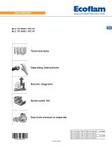
4.6 Maximum dimensions
The maximum dimensions of the burner are given in Fig. 1.
Bear in mind that inspection of the combustion head requires the
burner to be opened and the rear part turned on the hinge.
The maximum dimensions of the open burner are indicated by
the L and R positions.
The P position is reference for the refractory thickness of the boil-
er door.
Tab. E
** Maximum position for the extraction of the servomotor cover.
WARNING
* The gas adaptor is set also for DN 80 bore.
Fig. 1
20072082
mm A B C D E F* G H L M N O P** R
RS 310/EV MZ 1178 519 178 306 520 DN65 900 790 1015 400 528 290 177 890
RS 410/EV MZ 1178 519 178 306 520 DN65 940 790 1015 400 528 290 177 890
RS 510/EV MZ 1178 519 178 306 520 DN65 940 790 1015 400 528 290 177 890
RS 610/EV MZ 1178 500 178 330 520 DN65 980 790 1015 400 528 290 177 890

11 20081760
GB
Technical description of the burner
4.7 Firing rates
The MAXIMUM OUTPUT is chosen from within the diagram area
(Fig. 2).
The MINIMUM OUTPUT must not be lower than the minimum
limit of the diagram:
Tab. F
Model kW
RS 310/EV MZ 600
RS 410/EV MZ 800
RS 510/EV MZ 800
RS 610/EV MZ 820
WARNING
The firing rate value (Fig. 2) has been obtained
considering an ambient temperature of 20 °C, an
atmospheric pressure of 1013 mbar (approx. 0 m
a.s.l.), and with the combustion head adjusted as
shown on page 24.
Fig. 2
Thermal power – kW
Pressure in
combustion head - mbar
20072010
RS 310/EV
RS 410/EV
RS 510/EV
RS 610/EV

20081760 12
GB
Technical description of the burner
4.8 Test boiler
The burner/boiler combination does not pose any problems if the
boiler is EC approved and its combustion chamber dimensions
are similar to those indicated in the diagram (Fig. 3).
If the burner must be combined with a boiler that has not been EC
approved and/or its combustion chamber dimensions are clearly
smaller than those indicated in the diagram, consult the manufac-
turer.
The firing rates were set in relation to special test boilers, accord-
ing to EN 676 regulations.
In Fig. 3 you can see the diameter and length of the test combus-
tion chamber.
Example: RS 510/EV MZ
Output 7000 kW - diameter 120 cm - length 6m
4.9 Burner equipment
Gasket for gas train adaptor. . . . . . . . . . . . . . . . . . . . . . . . No. 1
Adaptor for gas train. . . . . . . . . . . . . . . . . . . . . . . . . . . . . . No. 1
Screws for fixing the gas train adaptor: M 16 x 70 . . . . . . No. 4
Thermal insulation screen . . . . . . . . . . . . . . . . . . . . . . . . . No. 1
M 18 x 60 screws to secure the burner flange to the
boiler . . . . . . . . . . . . . . . . . . . . . . . . . . . . . . . . . . . . . . . . . No. 4
Cable grommets kit for optional electrical wiring input . . . . No. 1
M16 nuts to fix the gas elbow to the pipe coupling . . . . . . No. 8
Stud bolts M16X60 to fix the gas elbow to the pipe
coupling . . . . . . . . . . . . . . . . . . . . . . . . . . . . . . . . . . . . . . . No. 1
Instructions . . . . . . . . . . . . . . . . . . . . . . . . . . . . . . . . . . . . No. 1
Spare parts list . . . . . . . . . . . . . . . . . . . . . . . . . . . . . . . . . No. 1
20057548 Fig. 3
Combustion chamber
m

13 20081760
GB
Technical description of the burner
4.10 Burner description
1 Lifting rings
2Fan
3Fan motor
4 Air damper servomotor
5 Combustion head gas pressure test point
6 Combustion head
7 Ignition electrode
8 Flame stability disk
9 Electrical panel casing
10 Gas butterfly valve servomotor
11 Fan air inlet
12 Pipe coupling
13 Gasket for boiler fixing
14 Gas butterfly valve
15 Shutter
16 Combustion head movement screw
17 Lever for controlling the dampers with graduated scale
18 Air pressure switch
19 Combustion head air pressure test point
20 Maximum gas pressure switch with pressure test point
21 Flame sensor probe
22 Hinge for opening the burner
23 Pressure test point for air pressure switch “+”
24 Combustion head air pressure test points
25 Gas train adapter
26 Indication for checking the rotation direction of the purging
motor
27 Flame inspection window
28 Provision for flame sensor kit
29 Reset button
30 Transparent protection
31 Rpm sensor
15
6
19
116
27
1
18
9
17 11 4
20
14
8
29
30
21
7
25
22 28
24
12
5
13
10
26
3
2
23
31
20082864
Fig. 4
ASSEMBLY VIEW
The burner can be opened to the right or to the left
without links to the fuel supply side.
WARNING
To open the burner see section “Access to head
internal part” on page 23.

20081760 14
GB
Technical description of the burner
4.11 Electrical panel description
1 Electrical control box
2 ON/OFF selector
3 Output regulator
4 Earth terminal
5 Supply cables and external connections passage. See sec-
tion “Electrical wiring” on page 29.
6 Bracket for applying the kits
7 Main terminal supply board
8 Relay with clean contacts for signalling the burner is in lock-
out
9 Relay with clean contacts for signalling the burner is operat-
ing
10 Auxiliary circuits fuse (includes a spare fuse)
11 Air pressure switch
12 Ignition transformer
13 Ionisation probe cable
14 Operator panel with LCD display
15 Light signalling burner lockout
16 Reset button
17 Relay with clean contacts for VSD signal
18 Relay with clean contacts
19 Control terminal board 4-20 mA
12
14
6
2
5
4
4
13
4
4
5
7
4
3
16
15
1
11
9
19
18
17
8
10
Fig. 5
20081976

15 20081760
GB
Technical description of the burner
4.12 Control box for the air/fuel ratio (REC37...)
Warnings
The control box is a system to check the burners, based on a mi-
croprocessor and equipped with components to adjust and su-
pervise medium and large capacity forced draught burners.
The control box contains the following components:
– burner management system with valve leak detection control
device;
– electronic device to check the fuel/air ratio with a maximum
of 2 actuators;
– Modbus interface.
All interventions (assembly and installation operations,
assistance, etc.) must be carried out by qualified personnel.
Before carrying out any checks on the wiring, fully isolate the
system from the electric mains (omnipolar separation).
Check the system is not powered and cannot be accidentally
reconnected. Failure to do this will lead to the risk of electro-
cution.
Protection against electrocution from the control box and all
connected electric components is obtained with the correct
assembly.
After every intervention (assembly and installation opera-
tions, assistance, etc.), ensure the wiring is in order and that
the parameters are correctly set, then perform the safety
checks.
Falls and collisions can negatively affect the safety func-
tions. In this case, the control box must not be operated,
even if it displays no evident damage.
During the programming of the air-fuel ratio control curves,
the technician should constantly observe the quality of the
combustion process (for example using a gas analyser) and,
in the event of inadequate combustion values or dangerous
conditions, should take appropriate action, for example shut-
ting down the system manually.
The plugs of the connection cables or other accessories can
be disconnected when the system has been switched off.
The connections to the actuators do not provide a secure
separation from the mains voltage. Before connecting or
changing the actuators the system should be off to avoid any
conditions that could cause the formation of condensation or
humidity. Otherwise, before switching on again, make sure
that the entire control box is perfectly dry!
Static charges must be avoided since they can damage the
control box’s electronic components when touched.
Static charges must be avoided since they can damage the
control box’s electronic components when touched.
WARNING
To avoid accidents, material and/or environmental
damage, observe the following instructions!
The control box is a safety device! Avoid opening
or modifying it, or forcing its operation. Riello
S.p.A. cannot assume any responsibility for dam-
age resulting from unauthorised interventions!
Risk of explosion!
An incorrect configuration can provoke fuel over-
charging, with the consequential risk of explosion!
The operators must be aware that the incorrect
setting of the visualisation and operation control
box, and of the positions of the fuel and/or air ac-
tuators, can cause dangerous conditions during
burner operation.
WARNING
For the safety and reliability of the control box,
comply with the following instructions:
Fig. 6
D8266

20081760 16
GB
Technical description of the burner
Technical data
Tab. G
Control box Mains voltage AC 230 V -15% / +10%
Mains frequency 50 / 60 Hz ±6%
Power absorption < 30 W
Safety class I, with components in compliance with II and III, ac-
cording to DIN EN 60730-1
Load on
‘input’ terminals
Fuse on the control box (can be inspected) 6.3 AT
Undervoltage
– Safety switch-off from operating position to mains
voltage
– Restart when mains voltage picks up
< AC 186V
> AC 195V
Cable length – Main line AC 230 V
– Control load (TL1-TL2)
– External reset button (RS)
– Load exit (DC 0/2...10V)
– Fuel valve
– Other lines
Max. 100 m (100 pF / m)
Max. 20 m (100 pF/m)
Max 20 m (100 pF/m)
Max. 10 m (100 pF/m)
Max. 3 m (100 pF/m)
Max. 3 m (100 pF/m)
Environmental
conditions
Storage
– Climatic conditions
– Mechanical conditions
– Temperature range
– Humidity
DIN EN 60721-3-1
Class 1K3
Class 1M2
-20 ... +60 °C
< 95% RH
Transport
– Climatic conditions
– Mechanical conditions
– Temperature range
– Humidity
DIN EN 60721-3-2
Class 2K2
Class 2M2
-30 ... +60 °C
< 95% RH
Operation
– Climatic conditions
– Mechanical conditions
– Temperature range
– Humidity
DIN EN 60721-3-3
Class 3K3
Class 3M3
-20 ... +60 °C
< 95% RH
WARNING
Condensation, the formation of ice and the entry
of water are prohibited!

17 20081760
GB
Technical description of the burner
4.13 Operation sequence of the burner
t1
p
P
P
5 s 30 s
P
P
00 02 10 12 22 24 30 36 38 39 40 42
8)
44 6260 70 72 74 78 80 81 82 83 90
246245244243242248234233
212
230
0,6 s
227
229
244226230
6) 13)5)
27 s
214213
217 211
4)
9) 9)
2)
12)
7) 7) 7)
3)
Phase number
Thermostat/pressure switch
OUTPUT SIGNALS
Thermostat/pressure switch
Ionisation probe ION
Air pressure switch PA
Min. gas pressure switch
Min. gas pressure switch
Gas pressure switch for
PGVP leak detection control
Alternative to the control
safety TS
Fan motor MV
Transformer of
Safety valve VS
Fuel valve V1
Fuel valve V2
Pilot valve VP
Lock-out signal
indicator TL
SERVOMOTORS
Air Fuel
90°
Nominal load
Pos. of post-purging
Ignition load
Low flame
Pos. without load
0°
S9024
Fig. 7
Checking of
seal
Switching offStart-up
Timer 1 (parameters)
Timer 2 (parameters)
Timer 3 = max. phase time
Input signals
PGmin
PGMin
Max gas pressure switch
PGMax
CPI seal
TA ignition
90°
Nominal load
Pos. of post-purging
Ignition load
Low flame
Pos. without load
0°
RAST plug
X3-04 Pin 1/2
PIN number
X5-03 Pin 1/4
X10-05
X3-02 Pin 1/2
X5-01 Pin 2/3
X5-01 Pin 2/3
X5-02 Pin 2/3
X9-04 Pin 2/3
X5-02 Pin 2/3
X3-05 Pin 1
X4-02 Pin 2/3
X6-03 Pin 2/3
X8-02 Pin 1/3
X7-01 Pin 2/3
X7-02 Pin 2/3
X3-05 Pin 2
RAST plug
PIN number
X54
X53
Signal ON
Signal OFF
Both states are allowed
X74
VSD
Operation
Timer - Resolution - Ratio
INPUT SIGNALS
Pin 2 Pin 3/4
X10-06 Pin 1/2
90°
Nominal load
Pos. of post-purging
Ignition load
Low flame
Pos. without load
0°

20081760 18
GB
Technical description of the burner
4.13.1 List of phases
4.14 Operator panel operation
The REC37 ... control box is directly connected to the operator
panel (Fig. 8).
The buttons allow you to programme the operation and diagnos-
tics menus.
The burner management system is shown on the LCD display
(Fig. 9). To simplify the diagnostics, the display shows the oper-
ating status, type of problem, and when the problem arose.
4.14.1 Description of the symbols on the display
The brightness of the display can be adjusted from 0 ... 100%
with the parameter 126.
Phase Description
Ph00 Lockout phase
Ph02 Safety phase
Ph10 Closing paused
Ph12 Standby
Ph22 Fan motor (MV) = ON
Safety valve (VS) = ON
Ph24 The burner moves to the pre-purging position
Ph30 Pre-purging time
Ph36 The burner moves to the ignition position
Ph38 Ignition phase (TA) = ON
Ph39 Minimum gas pressure switch test (PGmin.)
Ph40 Fuel valve (V) = ON
Ph42 Ignition (TA) = OFF
Ph44 t44 = interval time 1
Ph60 Operation
Ph62 The burner moves to the switching off position
Ph70 t13 = post-combustion time
Ph72 The burner moves to the post-purging position
Ph74 t8 = post-purging time
Ph78 t3 = post-purging time
Ph80 emptying time (valve leak detection)
Ph81 Atmospheric time test (valve leak control)
Ph82 filling time (valve leak detection)
Ph83 pressure test time (valve leak detection)
Ph90 Standby time due to lack of gas
Phase Description
WARNING
Observe the procedures and adjustments
shown below.
All interventions (assembly and installation
operations, assistance, etc.) must be carried
out by qualified personnel.
If the display and operator panel are dirty,
clean them with a dry cloth.
Protect the panel from excessive tempera-
tures and liquids.
D9001 Fig. 8
Lock-out lamp
Flame presence
Valve powered
Ignition transformer
Fan motor powered
Pre-heater active
Heat request
Info mode active
Service mode active
Closure of servomotors
Opening of servomotors
Unit of measurement
Lockout
Parameter mode active
only for light oil burners
Vhmin s
D9000
powered
Fig. 9
/