Page is loading ...

1/16, 1/8 & 1/4 DIN Valve Motor Drive Controller
Quick Start Manual PK503 (0037-75486)
CAUTION: Installation should be only performed by
technically competent personnel. Local Regulations
regarding electrical installation & safety must be observed.
1. INSTALLATION
The models covered by this manual have three different DIN case sizes (refer to
section 10). Some installation details vary between models. These differences have
been clearly shown.
Note: The functions described in sections 2 thru 9 are common to all models.
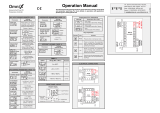
Installing Option Modules
1
/
16
Din Size Instruments
CPU PCB
Output Module 1
Output Module 2
Mounting Struts
Option Module A
Output Module 3
PSU PCB
1
/
8
&
1
/
4
Din Size Instruments
CPU PCB
Option Module B
Output Module 2
Output Module 1
Mounting Struts
Option Module A
Output Module 3
PSU PCB
To access modules 1, A or B, first detach the PSU and CPU boards from the front
by lifting first the upper, and then lower mounting struts. Gently separate the boards.
a. Plug the required option modules into the correct connectors, as shown below.
b. Locate the module tongues in the corresponding slot on the opposite board.
c. Hold the main boards together while relocating back on the mounting struts.
d. Replace the instrument by aligning the CPU and PSU boards with their guides
in the housing, then slowly push the instrument back into position.
Note: Option modules are automatically detected at power up.
Option Module Connectors
1
/
16
Din Size Instruments
Output Slot 1
Connectors
PL7 & PL8
Output Slot 2
Connector
PL4A
Option Slot A
Connectors
PL5 & PL6
Output Slot 3
Connector
PL4B
1
/
8
&
1
/
4
Din Size Instruments
Option Slot B
Connectors
PL2A, PL2B &
PL2C
Output Slot 2
Connector
PL4A
Output Slot 1
Connectors
PL7 & PL8
Option Slot A
Connectors
PL5 & PL6
Output Slot 3
Connector
PL4B
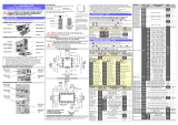
Panel-Mounting
The mounting panel must be rigid, and may be up to
6.0mm (0.25inch) thick. Cut-out sizes are:
Cut-Out Dim A Cut-Out Dim B
1
/
16
&
1
/
8
Din = 45mm
1
/
16
Din = 45mm
1
/
4
Din = 92mm
1
/
8
&
1
/
4
Din = 92mm
For n multiple instruments mounted side-by-side, cut-out
A is 48n-4mm (
1
/
16
&
1
/
8
Din) or 96n-4mm (
1
/
4
Din)
Tolerance +0.5, -0.0mm
Mounting Panel
Instrument
Housing
Ratchets
Gasket
Slide mounting clamp
over the instrument
housing towards rear face
of mounting panel until
the tongues engage in
ratchets and instrument is
clamped in position.
Hold instrument firmly in
position (apply pressure
to bezel only)
CAUTION: Do not remove the panel gasket; it is a seal against dust and
moisture.
Rear Terminal Wiring
USE COPPER CONDUCTORS (EXCEPT FOR T/C INPUT)
Single Strand wire gauge: Max 1.2mm (18SWG)
1
/
16
Din Size Instruments
1
/
8
&
1
/
4
Din Size Instruments
These diagrams show all possible option combinations. The actual
connections required depend on the exact model and options fitted.
*Note: This controller uses Three-Point Stepping Control. This requires two
identical outputs (2 Relays, 2 Triacs, 2 SSR Drivers or 1 Dual Relay) for the
valve Open & Close functions. See Output Usage 1-5 in Configuration Mode.
CAUTION: Check information label on housing for correct operating
voltage before connecting supply to Power Input
Fuse: 100 – 240V ac – 1amp anti-surge
24/48V ac/dc – 315mA anti-surge
Note: At first power-up the message Goto ConF
is displayed, as described in
section 7 of this manual. Access to other menus is denied until Configuration
Mode is completed.
2. SELECT MODE
Select mode is used to access the configuration and operation menu functions.
It can be accessed at any time by holding down and pressing .
In select mode, press or to choose the required mode, press to enter.
An unlock code is required to prevent unauthorised entry to Configuration, & Setup
modes. Press or to enter the unlock code, then press to proceed.
Mode
Upper
Display
Lower
Display
Description
Default
Unlock
Codes
Operator
Optr
SLCt
Normal operation
None
Set Up
Setp
SLCt
Tailor settings to the application
10
Configuration
ConF
SLCt
Configure the instrument for use
20
Product Info
inFo
SLCt
Check manufacturing information
None
Auto-Tuning
Atun
SLCt
Invoke Pre-Tune or Self-Tune
0
Note: The instrument will always return automatically to Operator mode if
there is no key activity for 2 minutes.
3. CONFIGURATION MODE
First select Configuration mode from Select mode (refer to section 2).
Press to scroll through the parameters, then press or to set the
required value. Press to accept the change, otherwise parameter will revert to
previous value. To exit from Configuration mode, hold down and press , to
return to Select mode.
Note: Parameters displayed depends on how instrument has been configured.
Refer to user guide (available from your supplier) for further details.
Parameters marked ** are repeated in Setup Mode.
Parameter
Lower
Display
Upper
Display
Adjustment range & Description
Default
Value
Input
Range/Type
inPt
See following table for possible codes
jC
Code
Input Type &
Range
Code
Input Type &
Range
Code
Input Type &
Range
bC
B: 100 - 1824 ºC
K.C
K: –128.8 - 537.7 ºC
P24F
PtRh20% vs 40%:
32 - 3362 ºF
bF
B: 211 - 3315 ºF
K.F
K: –199.9 - 999.9 ºF
CC
C: 0 - 2320 ºC
NC
N: 0 - 1399 ºC
PTC
Pt100: –199 - 800 ºC
CF
C: 32 - 4208 ºF
NF
N: 32 - 2551 ºF
PtF
Pt100: –328 - 1472 ºF
EC
E: –100 - 1000 ºC
rC
R: 0 - 1759 ºC
Pt.C
Pt100: –128.8 - 537.7 ºC
Ef
E: –148 - 1832 ºF
rF
R: 32 - 3198 ºF
Pt.F
Pt100: –199.9 - 999.9 ºF
E
.
C
E: –100.0 - 999.9 ºC
SC
S: 0 - 1762 ºC
0_20
0 - 20 mA DC
E
.
f
E: –148.0 - 999.9 ºF
SF
S: 32 - 3204 ºF
4_20
4 - 20 mA DC
JC
J: –200 - 1200 ºC
TC
T: –240 - 400 ºC
0_50
0 - 50 mV DC
JF
J: –328 - 2192 ºF
TF
T: –400 - 752 ºF
10.50
10 - 50 mV DC
J.C
J: –128.8 - 537.7 ºC
T.C
T: –128.8 - 400.0 ºC
0_5
0 - 5 V DC
J.F
J: –199.9 - 999.9 ºF
T.F
T: –199.9 - 752.0 ºF
1_5
1 - 5 V DC
KC
K: –240 - 1373 ºC
P24C
PtRh20% vs. 40%:
0 - 1850 ºC
0_10
0 - 10 V DC
KF
K: –400 - 2503 ºF
2_10
2 - 10 V DC
Note: Decimal point shown in table indicates temperature resolution of 0.1°
Parameter
Lower
Display
Upper
Display
Adjustment range & Description
Default
Value
Scale Range
Upper Limit
ruL
Scale Range Lower Limit +100
to Range Maximum
Range max
(Lin=1000)
Scale Range
Lower Limit
rLL
Range Minimum to
Scale Range Upper Limit -100
Range min
(Linear=0)
Decimal point
position
dPoS
0=XXXX, 1=XXX.X, 2=XX.XX, 3=X.XXX
(non-temperature ranges only)
1
Primary Output
Control Action
CTRL
reu
Reverse Acting
reu
dir
Direct Acting
Motor Travel
Time
TR
0..05 to 5 .00 (5 secs to 5 mins 0 secs)
Time Valve takes to move between its
physical end stops (full Open to full Closed).
1.00
Alarm 1Type
ALA1
P_Hi
Process High Alarm
P_Hi
P_Lo
Process Low Alarm
dE
Deviation Alarm
bAnd
Band Alarm
nonE
No alarm
High Alarm 1
value**
PhA1
Range Minimum to Range Maximum in
display units
Range Max
Low Alarm 1
value**
PLA1
Range Min
Band Alarm 1
value**
bAL1
1 LSD to span from setpoint in display units
5
Dev. Alarm 1
value**
dAL1
+/- Span from setpoint in display units
5
Alarm 1
Hysteresis**
AHY1
1 LSD to full span in display units
1
Alarm 2 Type**
ALA2
Options as for alarm 1
P_Lo
High Alarm 2
value**
PhA2
Range Max
Low Alarm 2
value**
PLA2
Range Min
Band Alarm 2
value**
AL
5
Parameter
Lower
Display
Upper
Display
Adjustment range & Description
Default
Value
Dev. Alarm 2
Value**
dAL2
Options as for alarm 1
5
Alarm 2
Hysteresis**
AHY2
1
Loop Alarm
LAEn
(disabled) or (enabled)
disA
Alarm Inhibit
Inhi
none
No alarms Inhibited
none
ALA1
Alarm 1 inhibited
ALA2
Alarm 2 inhibited
both
Alarm 1 and alarm 2 inhibited
Output 1 Usage*
USE1
OpN
Valve Open
OPN
CLs
Valve Close
Al_d
Alarm 1, Direct
A1_r
Alarm 1, Reverse
A2_d
Alarm 2, Direct
A2_r
Alarm 2, Reverse
LP_d
Loop Alarm, Direct
LP_r
Loop Alarm, Reverse
Or_d
Logical Alarm 1 OR 2, Direct
Or_r
Logical Alarm 1 OR 2, Reverse
Ad_d
Logical Alarm 1 AND 2, Direct
Ad_r
Logical Alarm 1 AND 2, Reverse
retS
Retransmit SP Output
retP
Retransmit PV Output
Linear Output 1
Range
tYP1
0_5
0 to 5 V DC output
0_10
0_10
0 to 10 V DC output
2_10
2 to 10 V DC output
0_20
0 to 20 mA DC output
4_20
4 to 20 mA DC output
Retransmit
Output 1 Scale
maximum
ro1H
-1999 to 9999
(display value at which output
will be maximum)
Range max
Retransmit
Output 1 Scale
minimum
ro1L
-1999 to 9999
(display value at which output
will be minimum)
Range min
Output 2 Usage*
USE2
As for output 1
Sec or Al2
Linear Output 2
Range
tYP2
As for output 1
0_10
Retransmit
Output 2 Scale
maximum
ro2H
-1999 to 9999
(display value at which output
will be maximum)
Range max
Retransmit
Output 2 Scale
minimum
ro2L
-1999 to 9999
(display value at which output
will be minimum)
Range min
Output 3 Usage*
USE3
As for output 1
Al_d
Linear Output 3
Range
tYP3
As for output 1
0_10
Retransmit
Output 3 Scale
maximum
ro3H
-1999 to 9999
(display value at which output
will be maximum)
Range max
Retransmit
Output 3 Scale
minimum
ro3L
-1999 to 9999
(display value at which output
will be minimum)
Range min
Output 4 Usage*
USE4
As for output 1 except Retransmit of PV or
SP is not possible.
OPN
Output 5 Usage*
USE5
AL_d
Display Strategy
disp
1, 2, 3, 4, 5 or 6 (refer to section 8)
1
Serial
Communications
Protocol
Prot
Mm
Modbus with no parity
Mmbn
Mm
Modbus with Even Parity
Mm
Modbus with Odd Parity
Serial
Communications
Bit Rate
bAud
1.2
1.2 kbps
4.8
2.4
2.4 kbps
4.8
4.8 kbps
9.6
9.6 kbps
19.2
19.2 kbps
Comms Address
Addr
1
1 to 255
1
Comms Write
CoEn
r_Ww
Read/Write
r_Ww
r_0
Read only
Auxiliary Input A
Usage
AiPA
rSP
Remote Setpoint (basic)
Pin
Pin
Valve Position Indication (basic)
Auxiliary Input B
Usage
AiPB
rSP
Remote Setpoint (Full)
Pin
Pin
Valve Position Indication (Full)
Digital Input 1
Usage
diGi
diS1
Setpoint 1 / Setpoint 2 select**
diS1
diAs
Automatic / Manual select
Digital Input 2
Usage
diG2
diS1
Setpoint 1 / Setpoint 2 select**
dirS
diAs
Automatic / Manual select
Remote / Local setpoint select
Note: diG2 has priority over diGi if both are configured for the same usage.
If
diGi or diG2 = diS1 the remote setpoint (RSP) input is disabled.
Continued on next page…
A
B
OUTPUT
OUTPUT
OUTPUT 1
OUTPUT 1
OUTPUT
OUTPUT

Parameter
Lower
Display
Upper
Display
Adjustment range & Description
Default
Value
Remote Auxiliary
Input Range
rinP
0_20
0 to 20 mA DC input
0_10
4_20
4 to 20 mA DC input
0_10
0 to 10 V DC input
2_10
2 to 10 V DC input
0_5
0 to 5 V DC input
1_5
1 to 5 V DC input
100
0 to 100mV DC input
Available on
full Aux.
(Slot B) only
Pot
Potentiometer
(2KΩ minimum)
RSP Upper Limit
rSPu
-1999 to 9999. Remote SP for max. input
Range max
RSP Lower Limit
rSPL
-1999 to 9999. Remote SP for min. input
Range min
RSP Offset
rSPo
Constrained within Scale Range Upper &
Scale Range Lower limits
0
Configuration
Lock Code
CLoc
0 to 9999. Unlock Code for this mode
20
4. SETUP MODE
Note: Configuration must be completed before adjusting Setup parameters.
First select Setup mode from Select mode (refer to section 2). The MAN LED
will light while in Setup mode. Press to scroll through the parameters,
then press or to set the required value.
To exit from Setup mode, hold down and press to return to Select mode.
Note: Parameters displayed depends on how instrument has been configured.
Parameter
Lower
Display
Upper Display Adjustment
Range & Description
Default
Value
Input Filter Time Constant
FiLt
0 0 (Off) or 0.5 to100.0 secs.
2.0
Process Variable Offset
OFFS
±Span of controller
0
Primary Proportional
Band
Pb_P
0 5 to 999.9 % of input span
10.0
Automatic Reset
(Integral Time)
Arst
0.01 to 99.59
1 sec to 99 mins 59 secs
5.00
Rate (Derivative Time)
rATE
0.00 to 99.59
0 sec to 99 mins 59 secs
0.00
Setpoint Upper Limit
SPuL
Current Setpoint to Range max
R/max
Setpoint Lower limit
SPLL
Range min to Current Setpoint
R/min
Minimum Motor On Time
ton
.. secs to (Motor Travel Time /
10) secs. The minimum drive
effort to begin moving valve.
0.0
Set Valve Open Position
PcuL
See instructions below to set the
valve’s fully open and closed
positions.
Max. Aux.
Set Valve Closed Position
PcLL
Min. Aux.
Valve Open Limit
PiuL
PiLL +1 to100. The maximum
position valve will be driven to
100
Valve Closed Limit
PiLL
0 to PiuL -1. The minimum
position valve will be driven to
0
High Alarm 1 value
PhA1
Range Minimum to Range
Maximum
R/max
Low Alarm 1 value
PLA1
R/min
Deviation Alarm 1 Value
dAL1
±Span from SP in display units
5
Band Alarm 1 value
bAL1
1 LSD to span from setpoint
5
Alarm 1 Hysteresis
AHY1
1 LSD to full span in display units
1
High Alarm 2 value
PhA2
Range Minimum to Range
Maximum
R/max
Low Alarm 2 value
PLA2
R/min
Deviation Alarm 2 Value
dAL2
±Span from SP in display units
5
Band Alarm 2 value
bAL2
1 LSD to span from setpoint
5
Alarm 2 Hysteresis
AHY2
1 LSD to full span in display units
1
Auto Pre-tune
APT
diSA (disabled) or
EnAb (enabled)
diSA
Auto/manual Control
selection
PoEn
Setpoint Select shown in
Operator Mode
SSEn
Setpoint ramp adjustment
shown in Operator Mode
Spr
SP Ramp Rate Value
rP
1 to 9999 units/hour or Off (blank)
Off
Setpoint Value
SP
Scale range upper to lower limits.
(when dual or remote setpoint
options are used,
SP is replaced by
P1 & SP2 or LS
or * before the legend
indicates the currently active SP)
Scale
Range
Minimum
Local Setpoint Value
_LSP
Setpoint 1 Value
_SP1
Setpoint 2 Value
_SP2
Setup Lock Code
SLoc
0 to 9999
10
Setting the Valve Opened & Valve Closed Positions
With PcuL in the lower display press . The top display shows oPnG.
Press to drive open the valve until it reaches the “fully open” end stop.
Press . The top display will go Blank and the Auxiliary Input value will be
measured and stored as the value equal to the fully open valve position.
Press . The lower display shows PcLL. Press . The top display shows cLSg.
Press to drive closed the valve until it reaches the “fully closed” end stop.
Press . The top display will go Blank and the Auxiliary Input value will be
measured and stored as the value equal to the fully closed valve position.
5. AUTOMATIC TUNING MODE
First select Automatic tuning mode from Select mode (refer to section 2).
Press to scroll through the modes, then press or to set the required
value.
To exit from Automatic tuning mode, hold down and press , to return to
Select mode.
Pre-tune is a single-shot routine and is thus self-disengaging when complete.
If APT in Setup mode = EnAb, Pre-tune will attempt to run at every power up*.
Refer to the full user guide (available from your supplier) for details on controller
tuning.
Parameter
Lower
Display
Upper Display
Default
Value
Pre-Tune
Ptun
On or OFF. *Pre-tune will not engage if setpoint
is ramping, or the PV is less than 5% of input
span from the setpoint . Indication remains
Off
Self-Tune
Stun
Tune Lock
tLoc
0 to 9999
6. PRODUCT INFORMATION MODE
First select Product information mode from Select mode (refer to section 2).
Press to view each parameter. To exit from Product Information mode,
hold down and press to return to Select mode.
Note: These parameters are all read only.
Parameter
Lower
Display
Upper
Display
Description
Input type
In_1
Uni
Universal input
Option 1 module type
fitted
OPn1
nonE
No option fitted
rLy
Relay output
SSr
SSR drive output
tri
Triac output
Lin
Linear DC voltage / current output
Option 2 module type
fitted
OPn2
nonE
No option fitted
drLy
Dual Relay output
rLy
Relay output
SSr
SSR drive output
tri
Triac output
Lin
Linear DC voltage / current output
dc24
Transmitter power supply
Option 3 module type
fitted
OPn3
As Option 2
Auxiliary Option A
module type fitted
OPnA
none
No option fitted
r485
RS485 communications
diGi
Digital Input*
rSPi
Auxiliary Input (basic)*
Auxiliary Option B
module type fitted
OPnb
none
No option fitted
rSPi
Auxiliary Input (full)
and Digital Input 2*
Firmware type
F(J
Value displayed is firmware type number
Firmware issue
Iss
Value displayed is firmware issue number
Product Revision Level
PRL
Value displayed is Product Revision level
Date of manufacture
dOMm
Manufacturing date code (mmyy)
Serial number 1
Sn1
First four digits of serial number
Serial number 2
Sn2
Middle four digits of serial number
Serial number 3
Sn3
Last four digits of serial number
7. MESSAGES & ERROR INDICATIONS
These messages indicate that an error has occurred, or there is a problem with the
process variable input connection or signal.
Caution: Do not continue with the process until the issue is resolved.
Parameter
Upper
Display
Lower
Display
Description
Instrument
parameters are in
default conditions
Goto
ConF
Configuration & Setup required. This screen
is seen at first turn on, or if hardware
configuration has been changed. Press .
to enter the Configuration Mode, next press
or to enter the unlock code number,
then press to proceed
Input Over Range
[HH]
Normal
Process variable input > 5% over-range
Input Under Range
[LL]
Normal
Process variable input > 5% under-range
Input Sensor Break
OPEN
Normal
Break detected in process variable input
sensor or wiring.
Aux. Over Range
Normal
[HH] **
Auxiliary input over-range
** also seen
wherever Aux
value would be
displayed
Aux. Under Range
Normal
[LL] **
Auxiliary input under-range
Auxiliary Input
Break
Normal
OPEN
**
Break detected in Auxiliary
input signal
Option 1 Error
ERR
Opn1
Option 1 module fault
Option 2 Error
pn2
Option 2 module fault
Option 3 Error
Opn3
Option 3 module fault
Option A Error
OpnA
Option A fault or Aux fitted in both A & B
Option B Error
Opnb
Option B module fault
8. OPERATOR MODE
This mode is entered at power on, or accessed from Select mode (see section 2).
Note: All Configuration mode and Setup mode parameters must be set as
required before starting normal operations.
Press to scroll through the parameters, then press or to set the
required value.
Note: All Operator Mode parameters in Display strategy 6 are read only (see
in configuration mode), they can only be adjusted via Setup mode.
Upper
Display
Lower
Display
Display Strategy and
When Visible
Description
PV Value
Active
SP
Value
1 & 2 (initial screen)
PV and target value of selected SP
Local Setpoints are adjustable in
Strategy 2
PV Value
Actual
SP
Value
3 & 6 (initial screen)
PV and actual value of selected SP
(e.g. ramping SP value). Read only
PV Value
(Blank)
4 (initial screen)
Process variable only
Read only
Active SP
Value
(Blank)
5 (initial screen)
Target value of selected setpoint
only. Read only
PV Value
Auxiliary
Input
Value
7 (initial screen)
PV and Valve Position or Flow
Read only
SP Value
SP
1, 3, 4, 5 & 6 if digital
input is not diS1 and
RSP not fitted
Target value of SP
Adjustable except in Strategy 6
SP1 Value
_SP1
Digital input = diS1.
__ lit if active SP = SP1
Target value of SP1
Adjustable except in Strategy 6
SP2 Value
_SP2
Digital input = diS1.
_ lit if active SP = SP2
Target value of SP2
Adjustable except in Strategy 6
Local SP
Value
_LSP
RSP fitted.
_ or lit if the
active SP = LSP
Target value of local setpoint
Adjustable except in Strategy 6
Remote SP
Value
_rSP
RSP fitted.
_ or * lit if the
active SP = rSP
Target value of remote setpoint
Read only
diGi,
LSP or rSP
SPs
RSP is fitted, digital
input is not diS1 and
SSEn is enabled in
Setup mode
Selects local/remote active setpoint
LSP = local SP, rSP = remote SP
diGi = selection via digital input (if
configured). Note: selecting LSP or
rSP will override digital input,
active SP indication changes to
Adjustable except in Strategy 6
Actual SP
Value
SPrP
is not blank
Actual (ramping) value of
selected SP. Read only
Ramp Rate
rP
enabled in
Setup mode
SP ramping rate, in units per hour
Adjustable except in Strategy 6
Active Alarm
Status
ALSt
When one or more
alarms are active.
ALM indicator
will also flash
L Alarm 2 active
L2 Alarm 1 active
L Loop Alarm active
Manual Valve Control
If PoEn is set to EnAb in Setup mode, manual control can be selected/de-selected
by pressing the key in Operator mode, via serial communications, or by
changing the status of a digital input if diGi or diG2 has been configured for diAs
in Configuration mode.
While in Manual Control mode, the indicator will flash and the lower display will
show Mman. If Valve Position Indication is configured, the lower display will show
pxxx instead of Mman , where xxx is the valve position as read by the Auxiliary
Input. p0 means the valve is fully closed, p100 means the valve is fully opened.
Press to move the valve mother in the “open” direction or to move the
valve mother in the “close” direction. Keep pressing the key until the desired valve
position is achieved
9. SERIAL COMMUNICATIONS
Refer to the full user guide (available from your supplier) for details.
10. SPECIFICATIONS
UNIVERSAL INPUT
Thermocouple
Calibration:
±0.1% of full range, ±1LSD (±1°C for Thermocouple CJC).
BS4937, NBS125 & IEC584.
PT100 Calibration:
±0.1% of full range, ±1LSD.
BS1904 & DIN43760 (0.00385
Ω
/
Ω
/°C).
DC Calibration:
±0.1% of full range, ±1LSD.
Sampling Rate:
4 per second.
Impedance:
>10MΩ resistive, except DC mA (5Ω) and V (47kΩ).
Sensor Break
Detection:
Thermocouple, RTD, 4 to 20 mA, 2 to 10V and 1 to 5V ranges
only. “Close Valve” outputs turn ON.
Isolation:
Isolated from all outputs (except SSR driver).
Universal input must not be connected to operator accessible
circuits if relay outputs are connected to a hazardous voltage
source. Supplementary insulation or input grounding would
then be required.
AUXILIARY INPUT
Calibration:
±0.25% of input range ±1 LSD.
Sampling Rate:
4 per second.
Sensor Break
Detection:
4 to 20 mA, 2 to 10V and 1 to 5V ranges only. Valve control
outputs turn off if RSP is the active SP.
Isolation:
Slot A - Basic isolation, Slot B - Reinforced safety isolation
from other inputs and outputs.
DIGITAL INPUTS
Volt-free(or TTL):
Open(2 to 24VDC) = SP1, Local SP or Auto Mode,
Closed(<0.8VDC) = SP2, Remote SP or Manual Mode.
Isolation:
Reinforced safety isolation from inputs and other outputs.
OUTPUTS
Relay
Contact Type &
Rating:
Single pole double throw (SPDT); 2A resistive.
120VAC max. (240V for alarm or indirect switching of valves).
Lifetime:
>500,000 operations at rated voltage/current.
Isolation:
Basic Isolation from universal input and SSR outputs.
Dual Relay
Contact Type &
Rating:
2 x single pole single throw, with shared common; 2A resistive.
120VAC max. (240V for alarm or indirect switching of valves).
Lifetime:
>200,000 operations at rated voltage/current.
Isolation:
Reinforced safety isolation from inputs and other outputs.
SSR Driver
Drive Capability:
SSR drive voltage >10V into 500Ω min.
Isolation:
Not isolated from universal input or other SSR driver outputs.
Triac
Operating Voltage:
20 to 140Vrms (280V max. for alarm or indirect switching of
valves) @ 47 to 63Hz.
Current Rating:
0.01 to 1A (full cycle rms on-state @ 25°C);
derates linearly above 40°C to 0.5A @ 80°C.
Isolation:
Reinforced safety isolation from inputs and other outputs.
DC Linear
Resolution:
8 bits in 250mS (10 bits in 1s typical, >10 bits in >1s typical).
Isolation:
Reinforced safety isolation from inputs and other outputs.
Transmitter PSU
Power Rating:
19 to 28V DC (24V nominal) into 910Ω minimum resistance.
Isolation:
Reinforced safety isolation from inputs and other outputs.
SERIAL COMMUNICATIONS
Physical:
RS485, at 1200, 2400, 4800, 9600 or 19200 bps.
Protocol:
Modbus RTU.
Isolation:
Reinforced safety isolation from all inputs and outputs.
OPERATING CONDITIONS (FOR INDOOR USE)
Ambient
Temperature:
0°C to 55°C (Operating), –20°C to 80°C (Storage).
Relative Humidity:
20% to 95% non-condensing.
Supply Voltage and
Power:
100 to 240VAC ±10%, 50/60Hz, 7.5VA
(for mains powered versions), or
20 to 48VAC 50/60Hz 7.5VA or 22 to 65VDC 5W
(for low voltage versions).
ENVIRONMENTAL
Standards:
CE, UL, ULC.
EMI:
Complies with EN61326 (Susceptibility & Emissions).
Safety
Considerations:
Complies with EN61010-1 & UL3121.
Pollution Degree 2, Installation Category II.
Front Panel Sealing:
To IP66 (IP20 behind the panel).
PHYSICAL
Front Bezel Size:
1
/
16
Din = 48 x 48mm,
1
/
8
Din = 96 x 48mm,
1
/
4
Din = 96 x 96mm.
Depth Behind Panel:
1
/
16
Din = 110mm, ,
1
/
8
&
1
/
4
Din = 100mm.
Weight:
0.21kg maximum.
PK503
0037-75486
November, 2014
/