Page is loading ...

Digital indicator model DI30 GB
14037419 • V2.3 • 02/2012
Digital indicator model DI30
for panel mounting or wall mounting
Operating instructions

2 WIKA operating instructions digital indicator DI30
GB Operating instructions model DI30 page
1 - 40
© 2010 WIKA Alexander Wiegand SE & Co. KG
All rights reserved.
WIKA® is a registered trademark in various countries.
Prior to starting any work, read the operating instructions!
Keep for later use!

WIKA operating instructions digital indicator model DI30 3
Contents
1 General information ................................................................................ 4
2 Safety ....................................................................................................... 5
2.1 Intended use ........................................................................................ 5
2.2 Personnel qualification......................................................................... 7
2.3 Special hazards ................................................................................... 7
2.4 Labelling / Safety marks ...................................................................... 8
3 Specifications .......................................................................................... 9
4 Design and function .............................................................................. 11
4.1 Short description ................................................................................ 11
4.2 Scope of delivery ............................................................................... 12
5 Transport, packaging and storage ....................................................... 12
5.1 Transport ........................................................................................... 12
5.2 Packaging .......................................................................................... 12
5.3 Storage .............................................................................................. 12
6 Commissoning, operation .................................................................... 13
6.1 Mounting ............................................................................................ 13
6.2 Electrical connection .......................................................................... 16
6.3 Function and operation description .................................................... 19
6.4 Programming ..................................................................................... 22
6.5 Description of the measuring input .................................................... 24
6.6 Description of device parameters ...................................................... 26
6.7 Program number table ....................................................................... 30
6.8 Default values .................................................................................... 32
7 Maintenance and cleaning .................................................................... 32
7.1 Maintenance ...................................................................................... 32
7.2 Cleaning ............................................................................................ 32
8 Faults ..................................................................................................... 33
9 Dismounting, return and disposal ....................................................... 34
9.1 Dismounting ...................................................................................... 34
9.2 Return ............................................................................................... 34
9.3 Disposal ............................................................................................. 35
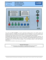
10 Application example: DI30 and gas cylinder scale GCS-1 ................. 36
11 Appendix: Declaration of conformity ................................................... 38
Declarations of conformity can be found online at www.wika.com.

1 General information
4 WIKA operating instructions digital indicator DI30
1 General information
The instrument described in the operating instructions has been
designed and manufactured using state-of-the-art technology.
All components are subject to stringent quality and environmental
criteria during production. Our management systems are certified to
ISO 9001.
These operating instructions contain important information on handling
the instrument. Working safely requires that all safety instructions and
work instructions are observed.
Observe the relevant local accident prevention regulations and general
safety regulations for the instrument's range of use.
The operating instructions are part of the instrument and must be kept
in the immediate vicinity of the instrument and readily accessible to
skilled personnel at any time.
Skilled personnel must have carefully read and understood the
operating instructions, prior to beginning any work.
The manufacturer's liability is void in the case of any damage caused by
using the product contrary to its intended use, non-compliance with
these operating instructions, assignment of insufficiently qualified skilled
personnel or unauthorised modifications to the instrument.
The general terms and conditions, contained in the sales
documentation, shall apply.
Subject to technical modifications.
Further information:
- Internet address: www.wika.de / www.wika.com
- Relevant data sheet: AC 80.05
- Application consultant: Tel.: (+49) 9372/132-0
Fax: (+49) 9372/132-406
E-Mail: [email protected]

2 Safety
WIKA operating instructions digital indicator model DI30 5
Explanation of symbols
WARNING!
... indicates a potentially dangerous situation that can result
in serious injury or death, if not avoided.
Information
... points out useful tips, recommendations and information
for efficient and trouble-free operation.
DANGER!
...identifies hazards caused by electric power. Should the
safety instructions not be observed, there is a risk of serious
or fatal injury.
2 Safety
WARNING!
Before installation, commissioning and operation, ensure that
the appropriate instrument has been selected in terms of
measuring range, design and specific measuring conditions.
Non-observance can result in serious injury and/or damage
to equipment.
Further important safety instructions can be found in the
individual chapters of these operating instructions.
2.1 Intended use
The DI30 is designed for the evaluation and display measuring transmitter
signals. With the alarm outputs, it is possible to perform simple control tasks.
The instrument has been designed and built solely for the intended use
described here, and may only be used accordingly.

2 Safety
6 WIKA operating instructions digital indicator DI30
Please read the following safety advice and the assembly before installation
and keep it for future reference.
If the instrument is transported from a cold into a warm environment, the
formation of condensation may result in the instrument malfunctioning. Before
putting it back into operation, wait for the instrument temperature and the
room temperature to equalise.
Notes on installation
There must be no magnetic or electric fields in the vicinity of the device,
e.g. due to transformers, mobile phones or electrostatic discharge.
Do not install inductive consumers (relays, solenoid valves etc.) near
the device and suppress any interference with the aid of RC spark
extinguishing combinations or free-wheeling diodes.
Keep input, output and supply lines separate from one another and do
not lay them parallel with each other. Position “go” and “return lines”
next to one another. Where possible use twisted pair. So, you receive
best measuring results.
Screen off and twist sensor lines. Do not lay current-carrying lines in the
vicinity. Connect the screening on one side on a suitable potential
equaliser (normally signal ground).
The device is not suitable for installation in areas where there is a risk
of explosion.
Any electrical connection deviating from the connection diagram can
endanger human life and/or can destroy the equipment.
The terminal area of the devices is part of the service. Here electrostatic
discharge needs to be avoided. Attention! High voltages can cause
dangerous body currents.
Galvanic insulated potentials within one complex need to be placed on
a appropriate point (normally earth or machines ground). So, a lower
disturbance sensibility against impacted energy can be reached and
dangerous potentials, that can occur on long lines or due to faulty
wiring, can be avoided.
The fuse rating of the supply voltage should not exceed a value of 1A
N.B. fuse.
The manufacturer shall not be liable for claims of any type based on
operation contrary to the intended use.

2 Safety
WIKA operating instructions digital indicator model DI30 7
2.2 Personnel qualification
WARNING!
Risk of injury should qualification be insufficient!
Improper handling can result in considerable injury and
damage to equipment.
The activities described in these operating instructions
may only be carried out by skilled personnel who have
the qualifications described below.
Keep unqualified personnel away from hazardous areas.
Skilled electrical personnel
Skilled electrical personnel are understood to be personnel who, based on
their technical training, knowledge of measurement and control technology
and on their experience and knowledge of country-specific regulations,
current standards and directives, are capable of carrying out work on
electrical systems and independently recognising and avoiding potential
hazards.
The skilled electrical personnel have been specifically trained for the work
environment they are working in and know the relevant standards and
regulations.
The skilled electrical personnel must comply with current legal accident
prevention regulations.
2.3 Special hazards
DANGER!
Danger of death caused by electric current.
Upon contact with live parts, there is a direct danger of
death.
Electrical instruments may only be installed and mounted
by skilled electrical personnel.
Operation using a defective power supply unit (e.g. short
circuit from the mains voltage to the output voltage) can
result in life-threatening voltages at the instrument!
WARNING!
Do NOT use this product as safety or emergency stopping
device, or in any other application where failure of the
product could result in personal injury or material damage.
Failure to comply with these instructions could result in
death or serious injury and material damage.

2 Safety
8 WIKA operating instructions digital indicator DI30
2.4 Labelling / Safety marks
Product label
1: power supply
2: order code
3: serial no.
4: CE mark
5: product name
6: connection diagram
Explanation of symbols
Before mounting and commissioning the instrument, ensure
you read the operating instructions!
CE, Communauté Européenne
Instruments bearing this mark comply with the relevant
European directives.

3 Specifications
WIKA operating instructions digital indicator model DI30 9
3 Specifications
Specifications
Display
Principle
7-Segment-LED, red, 4 digit
Character size
20 mm
Indication range
-999 … +9999
Indication time
0.1….10 sec
Memory
EEPROM (Parameter memory, Data storage >
20 years)
Input
Number and type
1 input for standard signals
Input signal
4...20 mA, input resistance ≤ 100 Ω or
0...20 mA, input resistance ≤ 100 Ω or
DC 0...5 V, input resistance ≥ 150 kΩ or
DC 0...10 V, input resistance ≥ 150 kΩ
Input configuration
selectable via terminal configuration and
programming
Accuracy
± 0.1 % of the measuring span ± 1 Digit
Temperature drift
All measuring inputs 50 ppm/K
Measuring principle
Voltage/Frequency converter
Resolution
approx. 20 bit, (at measuring time 1second)
Measuring time
0.1….10 sec
Transmitter supply
DC 24 V, max. 50 mA, galvanically isolated
Power supply
AC 230 V, 50/60 Hz, ± 10 %
{AC 115 V, 50/60 Hz, ± 10 %}
Power consumption
Max. 8 VA
Electrical connection
removable screw terminals
Line cross section up to 2.5 mm
2
Alarm output
Number and type
2 independent switching contacts (relays),
freely adjustable
Contact
load:
AC 230 V, 5 A (resistive load)
DC 30 V, 5 A (resistive load)
Switching cycles
0,5 * 10
5
at max. contact rating
5 * 10
6
mechanically
Separation as per DIN EN 50178
Characteristics as per DIN EN 60255

3 Specifications
10 WIKA operating instructions digital indicator DI30
Case
Material
Aluminium, black
Ingress protection
Front: IP 54, Rear: IP 00
Dimensions
96 x 96 x76 mm (w x h x d) including terminals
Mounting clearance
horizontal 120 mm / vertical 120 mm
(recommended)
Weight
Approx. 530 g
Mounting
sliding fasteners, fixed via screws, for panel
thicknesses from 1 mm to 10 mm
{Wall mounting
enclosure}
Material
ABS, black, cable gland
Ingress protection
IP 65
Dimensions
160 x 130 x 60 mm (w x h x d)
Cable gland
Cable thickness: 4.0...8.0 mm
Mounting
Fixing holes for screws
Permissible ambient conditions
Operating temperature
0…60 °C
Storage temperature
-20…80 °C
Humidity
0…75 % relative humidity, non-condensing
CE conformity
EMC directive
2004/108/EC, EN 61326-1 Emission (Group 1,
Class B) and Immunity (industrial locations)
Low voltage directive
2006/95/EC, EN 61010-1
{ } Items in curved brackets are optional extras for additional price.
For further specifications see WIKA data sheet AC 80.05 and the order
documentation.

4 Design and function
WIKA operating instructions digital indicator model DI30 11
Operating elements
1: Program key
2: DOWN key
3: UP key
4: Zero key
5: 7 segment display
6 +7: LEDs for displaying the alarm
contacts
4 Design and function
4.1 Short description
With the digital indicator DI30 standard signals DC 0/4…20 mA or DC
0…5/10 V can be measured. The 4 digit display shows the measurements or
the scaled value of the measurement. During programming the display is
used to indicate the set values and the user prompts.
Two relays (alarm outputs 1 and 2) are available to monitor threshold values,
the status of which is displayed via two separate LED on the front. The
integrated DC 24 V transmitter supply is used to supply connected sensors.

5 Transport, packaging and storage
12 WIKA operating instructions digital indicator DI30
4.2 Scope of delivery
The scope of delivery is:
Indicator for panel mounting:
Indicator
2 fixing elements
Seal
Operating instructions
Indicator for wall mounting:
Indicator
Operating instructions
Cross-check scope of delivery with delivery note.
5 Transport, packaging and storage
5.1 Transport
Check instrument for any damage that may have been caused by transport.
Obvious damage must be reported immediately.
5.2 Packaging
Do not remove packaging until just before mounting. Keep the packaging as it
will provide optimum protection during transport (e.g. change in installation
site, sending for repair).
5.3 Storage
Permissible conditions at the place of storage:
Storage temperature: -20 ... +80 °C
Humidity: 0 ... 75 % relative humidity (no condensation)
Avoid exposure to the following factors:
Direct sunlight or proximity to hot objects
Mechanical vibration, mechanical shock (putting it down hard)
Soot, vapour, dust and corrosive gases
Potentially explosive environments, flammable atmospheres

6 Commissoning, operation
WIKA operating instructions digital indicator model DI30 13
Store the instrument in its original packaging in a location that fulfils the
conditions listed above. If the original packaging is not available, pack and
store the instrument as described below:
1. Wrap the instrument in an antistatic plastic film.
2. Place the instrument, along with shock-absorbent material, in the
packaging.
3. If stored for a prolonged period of time (more than 30 days), place a
bag, containing a desiccant, inside the packaging.
WARNING!
Before storing the instrument (following operation), remove
any residual media. This is of particular importance if the
medium is hazardous to health, e.g. caustic, toxic,
carcinogenic, radioactive, etc.
6 Commissoning, operation
Please read the safety instructions and installation instructions in chapter 2
before installation and keep this user manual for future reference.
6.1 Mounting
Indicator for panel mounting:
Before assembly a cut-out must be made to accommodate the device. The
sizes and tolerances are given in the technical data.
On front of the DI30 are the operating and display elements. On the sides are
the fixing elements to mount the device in the panel. On the back are the
terminals for all the electrical connections. A gasket is inserted between the
contact surface of the front collar and the control panel.

6 Commissoning, operation
14 WIKA operating instructions digital indicator DI30
1. After removing the fixing elements, insert the device.
2. Check the seal to make sure it fits securely.
3. Click the fixing elements back into place and tighten the clamping
screws by hand. Then use a screwdriver to tighten them another half a
turn.
CAUTION! The torque should not exceed 0.1 Nm!
Indicator for wall mounting:
The wall-type housing consists of an upper part and a lower part. A suitable
seal has been inserted in the lower part to achieve protection IP 66. In the
upper part is the DI30 with its operating and display elements. On the back
are the terminals for all the electrical connections.

6 Commissoning, operation
WIKA operating instructions digital indicator model DI30 15
1. The cover flaps have to be opened on the right and left side. Loose the
four fixing screws, which connect the upper and lower part of the
enclosure, with a screw driver. Remove the upper part.
2. Fasten the enclosure to the wall.
3. Connecting cables have to be fed into the enclosure via the PG screws.
4. After connection the upper part of DI30 will be placed on the lower part.
Using the four fixing screws, screw the upper part to the lower part. Be
sure that the screws are completely tightened in order to attain ingress
protection IP66. Finally close the cover flaps again..
Screws for wall mounting are not part of scope of delivery.
Please use screws according to the material of the wall,
where you want to install the enclosure.

6 Commissoning, operation
16 WIKA operating instructions digital indicator DI30
6.2 Electrical connection
All the necessary signals for operation are connected to the rear terminals.
The connecting terminals are designed as removable screw-type terminals
with a grid pitch of 5.08 mm. This makes it possible to connect wires of up to
2.5 mm².
6.2.1 Terminal configuration
9-pole connector strip
On the 9-pole connector strip with terminals 1 to 9, the power supply (supply
voltage) of the digital indicator and the two relay outlets of the alarm outputs
are connected.
Power supply
4
5
6
N
PE
L
Relay 2 (A2)
Relay 1 (A1)
1
2
3
7
8
9
Com
Normally
open
Normally
closed
Com
Normally
open
Normally
closed
5-pole connector strip
On the 5-pole connector strip with terminals 10 to 14 the input signal and the
transmitter supply are connected.
Measuring input for standard signals
The input signal is connected to terminals 10 to 12. The DI30 has a voltage
input and a current input, to which most conventional sensors with a standard
signal output can be connected. The measuring input is galvanically isolated
from the power supply (supply voltage) and the transmitter supply.
Input for standard signals
Sensor signal
Measuring range
10
11
12
U (+) U (-)
0…5 V
0…10 V
-12…+12 V
I (+) I (-)
0…20 mA
4…20 mA
-24…+24 mA

6 Commissoning, operation
WIKA operating instructions digital indicator model DI30 17
Transmitter supply
The DC 24 V transmitter supply is available at terminals 13 and 14. The
transmitter supply is galvanic insulated from the measuring input. Current
loop sensors (2-wire) and 3-wire and 4-wire sensors can be operated via the
transmitter supply as long as their current consumption is not higher than 50
mA (Power consumption < 1.2 VA).
Transmitter supply
13
14
Transmitter supply (-)
Transmitter supply (+)
6.2.2 Connection Examples
This section gives a few examples of practical connections.
a) 4…20 mA signal, 2-wire-transmitter
b) 0…20 mA signal, 3-wire-transmitter
The voltage drop on the transmitter supply wire is irrelevant, which is
why this can also be bridged directly on the indicator.

6 Commissoning, operation
18 WIKA operating instructions digital indicator DI30
c) 0…5 V/0…10 V signal, 3-wire-transmitter
The ground is bridged via the sensor, which eliminates the measuring
error through the drop in voltage on the transmitter supply wires.

6 Commissoning, operation
WIKA operating instructions digital indicator model DI30 19
6.3 Function and operation description
6.3.1 Operation
The DI30 has 4 keys ([P], [
], [
], [O]), with which you can parameterise
and call up various functions during operation.
Additionally it has a 4-digit 7-segment display and two LEDs for displaying the
alarm contacts.
Name
Description
1
Program key [P]
With the program key, you can call up the
programming mode or perform various functions
in the programming mode.
2
DOWN key [▼]
With the DOWN (decrease) key, you can call up
the MIN memory or alter parameters in the
programming mode.
3
UP key [▲]
With the UP (increase) key, you can call up the
MAX memory or alter parameters in the
programming mode.
4
Zero key [O]
Zero key for TARA and HOLD function
5
7-segment display
In the 7-segment display measuring values are
displayed, respectively, during programming, the
program numbers or parameters are displayed.
6+7
Alarm displays
The alarm display indicates the state of the relays
of the alarm outputs. If a relay is switched, the
LED lights up..

6 Commissoning, operation
20 WIKA operating instructions digital indicator DI30
6.3.2 Switching on
Before switching on you have to check all the electrical connections to make
sure they are correct. On completion of the installation, the device can be
switched on by applying the power supply.
During the switching-on process a segment test is performed for approx. 1
second, whereby all LEDs on the front (including alarm LEDs) are triggered.
After this, the type of software is indicated for approx. 1 second and then,
also for 1 second, the software version. After the starting procedure, the unit
changes to operation/display mode.
6.3.3 General functions
MIN/MAX Memory
The measured minimum and maximum values are saved in a volatile memory
in the unit and get lost when the unit is switched off.
You can call up the contents of the memory by pushing (less than 1 second)
the [▲] or [▼] key. The relevant value is indicated for approx. 7 seconds. By
briefly pressing the same key again, you will return immediately to the display
mode.
[▲] Display of the MAX value
[▼] Display of the MIN value
You can erase the value shown in the display by simultaneously operating the
[▲] & [▼] keys. The erasure is acknowledged by horizontal bars.
The content of the memory is lost when the unit is switched off.
Overflow and Underflow
An overflow of the display is indicated by horizontal bars at the top of the 7-
segment display „ ¯ ¯ ¯ ¯ “.
An underflow of the display is indicated by horizontal bars at the bottom of the
7 segment display „ _ _ _ _ “
/