STECA Solarix MPPT 5020 Installation And Operating Instructions Manual
- Type
- Installation And Operating Instructions Manual
This manual is also suitable for
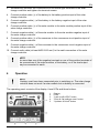
STECA Solarix MPPT 5020 is a powerful and efficient solar charge controller designed to optimize the performance of your solar system. With its advanced MPPT algorithm, it can extract the maximum available power from your solar panels, even in challenging conditions. It also features a three-stage charging process to extend the life of your batteries and protect them from damage. The backlit LCD display provides clear and concise information about your system's status, including battery voltage, charging current, and load status.
STECA Solarix MPPT 5020 is a powerful and efficient solar charge controller designed to optimize the performance of your solar system. With its advanced MPPT algorithm, it can extract the maximum available power from your solar panels, even in challenging conditions. It also features a three-stage charging process to extend the life of your batteries and protect them from damage. The backlit LCD display provides clear and concise information about your system's status, including battery voltage, charging current, and load status.


-
 1
1
-
 2
2
-
 3
3
-
 4
4
-
 5
5
-
 6
6
-
 7
7
-
 8
8
-
 9
9
-
 10
10
-
 11
11
-
 12
12
-
 13
13
-
 14
14
-
 15
15
-
 16
16
-
 17
17
-
 18
18
-
 19
19
-
 20
20
-
 21
21
-
 22
22
-
 23
23
-
 24
24
-
 25
25
-
 26
26
-
 27
27
-
 28
28
-
 29
29
-
 30
30
-
 31
31
-
 32
32


STECA Solarix MPPT 5020 Installation And Operating Instructions Manual
- Type
- Installation And Operating Instructions Manual
- This manual is also suitable for
STECA Solarix MPPT 5020 is a powerful and efficient solar charge controller designed to optimize the performance of your solar system. With its advanced MPPT algorithm, it can extract the maximum available power from your solar panels, even in challenging conditions. It also features a three-stage charging process to extend the life of your batteries and protect them from damage. The backlit LCD display provides clear and concise information about your system's status, including battery voltage, charging current, and load status.
Ask a question and I''ll find the answer in the document
Finding information in a document is now easier with AI
Related papers
Other documents
-
OutBack Power Alino TL Quick start guide
-
Samlexpower VT 65 Owner's manual
-
Mastervolt Mass Combi Ultra 24/3500-100 (230 V) User manual
-
Victron energy SmartSolar MPPT RS 450/100-Tr Owner's manual
-
-
Voltronic Power PIP-HS User manual
-
 MPP Solar PIP-HS User manual
-
 MPP Solar PIP-HS User manual
-
Bogart Engineering SC-2030 Technical Manual
-

