SmartCool™ Downow
60 to 140kW
Technical Manual
Direct Expansion
EMS52086FM00542
2X20
2X2C
2W20
2W2F

Customer Services
Warranty, Commissioning & Maintenance
As standard, Airedale guarantees all non consumable parts only for a period of 12 months, variations tailored to suit
product and application are also available; please contact Airedale for full terms and details.
To further protect your investment in Airedale products, Airedale can provide full commissioning services,
comprehensive maintenance packages and service cover 24 hours a day, 365 days a year (UK mainland).
For a free quotation contact Airedale or your local Sales Engineer.
All Airedale products are designed in accordance with EU Directives regarding prevention of build up of water,
associated with the risk of contaminants such as legionella.
For eff ective prevention of such risk it is necessary that the equipment is maintained in accordance with Airedale
recommendations. In addition to commissioning, a 24 hour, 7 days a week on-call service is available throughout the
year to UK mainland sites. This service will enable customers to contact a duty engineer outside normal working hours
and receive assistance over the telephone. The duty engineer can, if necessary, attend site, usually within 24 hours or
less.
Full details will be forwarded on acceptance of the maintenance agreement.
Warranty cover is not a substitute for maintenance. Warranty cover is conditional to maintenance
being carried out in accordance with the recommendations provided during the warranty period.
Failure to have the maintenance procedures carried out will invalidate the warranty and any
liabilities by Airedale International Air Conditioning Ltd.
Spares
A spares list for 1, 3 and 5 years will be supplied with every unit and is also available from our Spares department on
request.
Training
As well as our comprehensive range of products, Airedale off ers a modular range of Refrigeration and Air Conditioning
Training courses, for further information please contact Airedale.
Customer Services
For further assistance, please e-mail: [email protected] or telephone:
For information, visit us at our web site: www.airedale.com
Airedale Ltd endeavours to ensure that the information in this document is correct and fairly stated, but none of the
statements are to be relied upon as a statement or representation of fact. Airedale Ltd does not accept liability for any
error or omission, or for any reliance placed on the information contained in this document. The development of Airedale
products and services is continuous and the information in this document may not be up to date. It is important to check
the current position with Airedale Ltd at the address stated. This document is not part of a contract or licence unless
expressly agreed. No part of this document may be reproduced or transmitted in any form or by any means, electronic
or mechanical, including photocopying, recording, or information storage and retrieval systems, for any purpose other
than the purchaser’s personal use, without the express written permission of Airedale Ltd.
©2019 Airedale International Air Conditioning Limited. All rights reserved. Printed in the UK.
CAUTION
SmartCool™ 60 - 140kW DX Precision Air Conditioning
2
Introduction
SmartCool 60 - 140kW Direct Expansion Technical Manual 7968969 V1.13_10_2020

Health and Safety
IMPORTANT
The information contained in this manual is critical to the correct operation and maintenance of the unit and should be
read by all persons responsible for the installation, commissioning and maintenance of this Airedale unit.
Safety
The equipment has been designed and manufactured to meet international safety standards but, like any mechanical/
electrical equipment, care must be taken if you are to obtain the best results.
When working with any air conditioning units ensure that the electrical isolator is switched off prior to servicing or repair
work and that there is no power to any part of the equipment. Also ensure that there are no other power feeds to the unit
such as fi re alarm circuits, BMS circuits etc.
Personal Protective Equipment
Airedale recommends that personal protective equipment is used whilst installing, maintaining and commissioning
equipment.
Refrigerant Warning
The Airedale unit uses R410A refrigerant which requires careful attention to proper storage and handling procedures.
Use only manifold gauge sets designed for use with R410A refrigerant. Use only refrigerant recovery units and cylinders
designed for high pressure refrigerants. R410A must only be charged in the liquid state to ensure correct blend makeup.
The refrigerant must be stored in a clean, dry area away from sunlight. The refrigerant must never be stored above
50°C.
Maximum and Minimum Operation Temperature (TS) and Pressure (PS)
Refrigeration
Allowable Temperature Range (TS) = Min -5°C* to Max 120°C **
Maximum Allowable Pressure (PS) = High Side 40.5 Barg
*Based on the refrigerant temperature in the unit off state in the lowest permitted ambient temperature.
**Based on the refrigerant temperature in the unit off state
Waterside
Allowable Temperature Range (TS) = Min -5°C* to Max 55°C **
Maximum Allowable Pressure (PS) = High Side 10 Barg
*Based on the waterside temperature in the unit off state in the lowest permitted ambient temperature.
**Based on the waterside temperature in the unit off state in the highest permitted ambient temperature.
Pressure System Safety Regulations 2000
Refrigeration assemblies/systems may constitute a Pressure System as defi ned in the Pressure System Safety
Regulations 2000.
Global Warming Potential
The R410A refrigerant has a GWP of 2088 (based on EN378-1:2016, 100 year life)
Manual Handling
Some operations when servicing or maintaining the unit may require additional assistance with regard to manual
handling. This requirement is down to the discretion of the engineer. Remember do not perform a lift that exceeds your
ability.
Electrical installation commissioning and maintenance work on this equipment should be
undertaken by competent and trained personnel in accordance with local relevant standards and
codes of practice.
A full hazard data sheet in accordance with COSHH regulations is available should this be
required.
CAUTION
Precision Air Conditioning
SmartCool™ 60 - 140kW DX
3
SmartCool 60 - 140kW Direct Expansion Technical Manual 7968969 V1.13_10_2020
Introduction

Environmental Considerations
Units with supply water temperatures below +5°C
● Glycol is recommended when a supply water temperature of +5°C or below is required or when static water can
be exposed to freezing temperatures.
Units subject to ambient temperatures lower than 0°C
● Glycol of an appropriate concentration (1) must be used within the system to ensure adequate freeze protection.
Please ensure that the concentration is capable of protection to at least 3°C lower than ambient.
●Water / glycol solution should be constantly circulated through all waterside pipework and coils to avoid static
water from freezing.
●Ensure that pumps are started and running even during shut down periods, when the ambient is within 3°C of the
solution freeze point (1) (i.e. if the solution freezes at 0°C, the pump must be operating at 3°C ambient).
●Additional trace heating is provided for interconnecting pipework.
(1) Refer to your glycol supplier for details.
Environmental Policy
It is our policy to:
●Take a proactive approach to resolve environmental issues and ensure compliance with regulatory requirements.
●Train personnel in sound environmental practices.
●Pursue opportunities to conserve resources, prevent pollution and eliminate waste.
● Manufacture products in a responsible manner with minimum impact on the environment.
● Reduce our use of chemicals and minimise their release to the environment.
● Measure, control and verify environmental performance through internal and external audits.
●Continually improve our environmental performance.
CE Directive
Airedale certify that the equipment detailed in this manual conforms with the following EC Directives:
Electromagnetic Compatibility Directive (EMC) 2014/30/EU
Machinery Directive (MD) 89/392/EEC version 2006/42/EC
Pressure Equipment Directive (PED) 2014/68/EU
To comply with these directives appropriate national & harmonised standards have been applied. These are listed on the
Declaration of Conformity, supplied with each product.
SmartCool™ 60 - 140kW DX Precision Air Conditioning
4
Introduction
SmartCool 60 - 140kW Direct Expansion Technical Manual 7968969 V1.13_10_2020

System Congurations 7
Nomenclature 10
Introduction 10
Unit Overview 11
2X20 11
2X2C 11
2W20 12
2W2F 12
Chilled Water 14
Hydronics Kits 17
Refrigeration 18
Airow Components 22
Electrical Components 24
Humidication 28
Controls 31
General Features 36
Installation Data 39
Dimensions 39
Lifting 43
Positioning & Levelling 43
Unpacking 43
Minimum Unit Clearance 44
Pipework Schematics 45
Pipesizing 56
Refrigerant Charges 57
Incoming Services 59
Glycol 64
Oil Charging Guide 65
Humidier Bottle Information 67
Water Detection Tape Installation 70
Interconnecting Wiring 71
Technical Data 2X20 Units 76
Performance Data 2X20 76
SC22D050-2X20, SC22D059-2X20 78
SC22D064-2X20, SC22D074-2X20 80
SC25D062-2X20, SC25D068-2X20, SC25D075-2X20 82
SC25D085-2X20, SC25D092-2X20 84
SC31D069-2X20, SC31D079-2X20, SC31D089-2X20 86
SC31D094-2X20, SC31D108-2X20, SC31D124-2X20 88
SC35D079-2X20, SC35D091-2X20, SC35D098-2X20 90
SC35D111-2X20, SC35D127-2X20, SC35D140-2X20 92
Sound Data 94
Technical Data 2X2C Units 96
Performance Data 2X2C DX 96
Performance Data 2X2C Chilled Water 99
SC22D050-2X2C, SC22D059-2X2C 102
SC22D064-2X2C, SC22D074-2X2C 104
SC25D062-2X2C, SC25D068-2X2C, SC25D075-2X2C 106
SC25D085-2X2C, SC25D092-2X2C 108
SC31D069-2X2C, SC31D079-2X2C, SC31D089-2X2C 110
Contents
Precision Air Conditioning
SmartCool™ 60 - 140kW DX
5
SmartCool 60 - 140kW Direct Expansion Technical Manual 7968969 V1.13_10_2020
Introduction

SC31D094-2X2C, SC31D108-2X2C, SC31D124-2X2C 112
SC35D079-2X2C, SC35D091-2X2C, SC35D098-2X2C 114
SC35D111-2X2C, SC35D127-2X2C 116
Waterside Pressure Drop Data 118
Sound Data 119
Technical Data 2W20 Units 122
Performance Data 2W20 122
SC22D050-2W20, SC22D059-2W20 124
SC22D064-2W20, SC25D074-2W20 126
SC25D062-2W20, SC25D068-2W20, SC25D075-2W20 128
SC25D085-2W20, SC25D092-2W20 130
SC31D069-2W20, SC31D079-2W20, SC31D089-2W20 132
SC31D094-2W20, SC31D108-2W20, SC31D124-2W20 134
SC35D079-2W20, SC35D091-2W20, SC35D098-2W20 136
SC35D111-2W20, SC35D127-2W20 138
Waterside Pressure Drop Data 140
Sound Data 141
Technical Data 2W2F Units 143
Performance Data 2W2F 143
Performance Data 2W2F Free Cooling Mode 145
SC22D050-2W2F, SC22D059-2W2F 148
SC22D064-2W2F, SC22D074-2W20 150
SC25D062-2W2F, SC25D068-2W2F, SC25D075-2W2F 152
SC25D085-2W2F, SC25D092-2W2F 154
SC31D069-2W2F, SC31D079-2W2F, SC31D089-2W2F 156
SC31D094-2W2F, SC31D108-2W2F, SC31D124-2W2F 158
SC35D079-2W2F, SC35D091-2W2F, SC35D098-2W2F 160
SC35D0111-2W2F, SC35D127-2W2F 162
Waterside Pressure Drop Data 164
Sound Data 165
Commissioning Data 168
Humidier (Optional Extra) 168
Water Conductivity & Cylinder Type 170
Electronic Expansion Valves (EEV) 171
Head Pressure Control 171
Electronically Commutated (EC) Fan Motor 172
Fan Section 174
Chiller/Glycol units 175
Humidication 176
Refrigeration Circuit 177
Indoor unit optional extras 179
Maintenance 180
General Inspections 181
Electrical Inspection 182
Refrigeration 183
Waterside 184
Controls 185
System 186
Evaporator Fan Removal 187
Troubleshooting 188
After Sales 190
Warranty 190
Contents
SmartCool™ 60 - 140kW DX Precision Air Conditioning
6
Introduction
SmartCool 60 - 140kW Direct Expansion Technical Manual 7968969 V1.13_10_2020

System Congurations
DX Air Cooled – Dual Circuit (2X20)
Dual circuit DX air cooled with compressors located in the indoor unit. R410A xed capacity compressors will be
integrated into the design. Tandem compressor sets will be used to offer multiple cooling stages with xed speed
compressors.
Liquid Line
Discharge Line
Precision Air Conditioning
SmartCool™ 60 - 140kW DX
7
SmartCool 60 - 140kW Direct Expansion Technical Manual 7968969 V1.13_10_2020
Introduction

System Congurations
Dual Cool – DX Air Cooled and Chilled Water (2X2C)
Triple circuit, multi-cooling format – dual circuit DX air cooled and single circuit chilled water to support redundancy
specications in data centres. The cooling circuits will be congured for run/standby or ‘high temperature assist’ as
opposed to continuous concurrent cooling.
Liquid Line
Chilled Water Flow
Discharge Line
Chilled Water Return
SmartCool™ 60 - 140kW DX Precision Air Conditioning
8
Introduction
SmartCool 60 - 140kW Direct Expansion Technical Manual 7968969 V1.13_10_2020

Additional Dry Cooler
for Systems with THR >100kW
System Congurations
DX Water Cooled – Dual Circuit (2W20)
Dual circuit DX water cooled with compressors located in the indoor unit. R410A xed capacity compressors will be
integrated into the design. Tandem compressor sets will be used to offer multiple cooling stages with xed speed
compressors.
Free Cool – DX Water Cooled with Free Cooling (2W2F)
Dual circuit DX water cooled with free cooling chilled water coil.
The unit will have the ability to run in full free cooling mode (free cooling coil active), hybrid mode (DX circuit and free
cooling coil active) or mechanical cooling only (DX circuit active).
Additional pumps and valves may be
required (Not supplied by Airedale).
Dry Cooler Flow
Dry Cooler Return
Precision Air Conditioning
SmartCool™ 60 - 140kW DX
9
SmartCool 60 - 140kW Direct Expansion Technical Manual 7968969 V1.13_10_2020
Introduction

Nomenclature
Example: SC 22 D 064 -2 X 2 C -0
SC SmartCool Dedicated Direct Expansion
22 Case width in decimetres (2200mm)
25 Case width in decimetres (2500mm)
31 Case width in decimetres (3100mm)
35 Case width in decimetres (3500mm)
DFlow Configuration Downflow unit
050-140 Nominal Cooling Capacity (kW)
-Separator
2Dual DX Circuit
XAir Cooled - Compressor Indoors
WWater Cooled
2Number of compressor/circuit
0No Chilled Water Coil
CChilled Water
FFree Cool
-Separator
0Power Supply 400V/3~ & 230V/1~ 50Hz
Secondary Cooling Media
Coil Type
Introduction
Designed to provide environmental precision air conditioning for applications such as telecommunication facilities, data
centres, computer rooms, clean rooms and laboratories. Full function units provide full control of temperature, humidity
and ltration. The modular design of the SmartCool allows grouping of differing model types and capacities to be
installed side by side. The exibility of this type of installation provides for multi-circuit functionality.
Precision Air Conditioning System
The computer room air conditioning equipment shall be designed specically for precision temperature and humidity
control applications. It shall automatically monitor and control cooling, heating, humidication, de-humidication
and ltering functions for the conditioned space. The system shall be built to the highest quality engineering and
manufacturing standards and shall be subject to a functional test prior to leaving the factory.
Construction
The cabinet shall be manufactured using a steel frame. Panels shall be removable so that access can be gained to the
side and rear of the unit by removing panels during installation. The galvanised sheet steel panels and welded steel
frame shall be coated with an epoxy baked powder paint to provide a durable nish. Standard unit colour shall be Black
Grey to RAL 7021. Cabinets shall be lined internally with various thickness re resistant foam (BS 476) for thermal and
acoustic insulation. The insulation density shall not be less than 75 kg/m³. The cabinet doors shall be full height, hinged
and key lock secured. The hinge arrangement shall allow exible door opening/removal for improved access. A propriety
rubberised door seal shall reduce sound breakout and eradicate air leakage. In-seal type foam based door seals shall
not be acceptable. The unit design shall incorporate a series of M6 xings to the top and bottom face to ease customer
ductwork connection and reduce installation time.
SmartCool™ 60 - 140kW DX Precision Air Conditioning
10
Introduction
SmartCool 60 - 140kW Direct Expansion Technical Manual 7968969 V1.13_10_2020

Unit Overview
2X20
Humidifier
2 Way Chilled
Water Valve
Fans
Cooling Coil
Expansion Valve
Removable Door
Supports
Humidifier
Fans
Cooling Coil
Expansion
Valve
Removable Door
Supports
2X2C
Precision Air Conditioning
SmartCool™ 60 - 140kW DX
11
SmartCool 60 - 140kW Direct Expansion Technical Manual 7968969 V1.13_10_2020
Introduction

Brazed Plate Heat
Exchanger
Humidifier
2 port modulating
valve for HPC
2 Way Free Cooling
Water Valve
Fans
Cooling Coil
Expansion Valve
Removable Door
Supports
Brazed Plate Heat
Exchanger
Humidifier
2 Port Modulating
Valve for HPC
Cooling Coil
Expansion
Valve
Removable Door
Supports
Fans
Water Inlet (Left
Hand Side)
Water Outlet
(Right hand
side)
Auto Bypass Valve
Unit Overview
2W20
2W2F
SmartCool™ 60 - 140kW DX Precision Air Conditioning
12
Introduction
SmartCool 60 - 140kW Direct Expansion Technical Manual 7968969 V1.13_10_2020

DX Liquid Line Assembly
Differential Pressure
Switch
DX Pipework
Terminations.
(Circuit 1 left hand
side and Circuit 2 right
hand side of unit)
Fans Offset when Humidification Selected
High Efficient Backward
Curved Plug Fans
Drip Tray
Temp / Hum sensor
Unit Overview
Precision Air Conditioning
SmartCool™ 60 - 140kW DX
13
SmartCool 60 - 140kW Direct Expansion Technical Manual 7968969 V1.13_10_2020
Introduction

System Conguration
2X20 2X2C 2W20 2W2F
Chilled Water
Hydrophilic Epoxy Coated RTPF Chilled Water Coil – ● – ●
0-10 Volts Chilled Water Regulating Valve (2 Way) – ● – ●
Spool Piece (interconnection pipe work) – ● ● ●
Brazed Connections ● ● ● ●
Threaded Connections – ○ ○ ○
Grooved Connections – ○ ○ ○
Hydronics Kits – – ○ ○
● Standard Features ○ Optional Features – Feature Not Available
Chilled Water
2 Port modulating Valve for
Head Pressure Control
2 Port modulating
Valve for Free Cooling
Water Inlet Left
hand Side
Water Outlet Right hand
Side
Brazed Plate Condenser
2 port modulating valve for
pressure drop regulation
SmartCool™ 60 - 140kW DX Precision Air Conditioning
14
Introduction
SmartCool 60 - 140kW Direct Expansion Technical Manual 7968969 V1.13_10_2020

Chilled Water Coil
Chilled water coils shall be ideally positioned to optimise airow and heat transfer, they shall be manufactured from plain
copper tubes with mechanically bonded aluminium ns. Fins shall be coated with a non-stick acrylic lm (hydrophilic)
to provide additional corrosion protection and allow efcient surface water removal for improved performance. Plain
aluminium shall not be acceptable. The cooling coil shall be mounted over a full width stainless steel condensate tray.
For control of water ow, various valve options shall be tted.
The factory test pressure shall not be less than 20 Barg and the maximum operating pressure shall be less than 10
Barg.
Sweat copper pipe for brazed connection shall be standard. Optional threaded and Grooved connections shall be
available.
Threaded Water Pipe Connection
As an alternative to brazed water pipe connection, BSP brass male taper threaded connections shall be factory
available.
Grooved Water Connections
Grooved water connections shall be available enabling easy pipe work termination.
Precision Air Conditioning
SmartCool™ 60 - 140kW DX
15
SmartCool 60 - 140kW Direct Expansion Technical Manual 7968969 V1.13_10_2020
Introduction

Water Spool Pieces
The spool piece piping needs to be tted through the hole in the oor stand. A collar is factory tted to the pipework. The
clamp is tted with the rubber seal on-site once the unit is mounted on the oorstand.
Factory tted pipe
Removable pipe
The customer side of the spool piece has one of the following connections:
● Brazed
● Threaded (optional)
● Grooved (optional)
Please conrm customer side water connection at time of ordering.
SmartCool™ 60 - 140kW DX Precision Air Conditioning
16
Introduction
SmartCool 60 - 140kW Direct Expansion Technical Manual 7968969 V1.13_10_2020

The purpose of the hydronics kit shall be to facilitate the ow of water around the system. The Hydronics kit shall be
installed in series with a dry cooler (two where necessary) and the indoor unit, supplying chilled water to the free-cooling
coil or water for head pressure control in DX mode. The hydronics kit is not avaliable for chilled water only units. The unit
shall be unobtrusive with a minimal footprint and able to be installed inside a building, such as in a plant room or outside
a building, for example on a rooftop or at ground level hence necessitating water and freeze protection.
Four versions shall be available:
● Standalone Fixed Speed (HY11-1F)
● Standalone Variable Speed (HY11-1V)
● Run/Standby Fixed Speed (HY15-2F)
● Run/Standby Variable Speed (HY15-2V)
A microprocessor shall be used to control the pump(s) and the pressurisation unit (option) on all of the models in the
range as standard. The control panel enclosure shall also contain a heater as standard to ensure that the electronics
and the pressurisation unit will not drop below 0°C (based on a minimum ambient of -20°C. The control panel shall also
be ventilated to avoid the electronics getting too hot up to ambient temperatures of 40°C.
Hydronics Kits
Pumps
Run / Standby Pump MCB
Expansion Vessel
Inverters
Lifting Eyes
Dosing Pot
Flanges
Control Panel
Panel Heater
Weatherproof Enclosure
Precision Air Conditioning
SmartCool™ 60 - 140kW DX
17
SmartCool 60 - 140kW Direct Expansion Technical Manual 7968969 V1.13_10_2020
Introduction

Refrigeration
System Conguration
2X20 2X2C 2W20 2W2F
Refrigeration
Hydrophilic Evaporator Coil ● ● ● ●
Scroll Compressor ● ● ● ●
Electronic Expansion Valve ● ● ● ●
Brazed Plate Heat Exchanger – – ● ●
Sight Glass with Moisture Indicator ● ● ● ●
Liquid Line solenoid valves ● ● ● ●
Discharge non-return valve ● ● ● ●
Filter Drier ● ● ● ●
Head pressure Control to -20°C ● ● ● ●
Low Ambient Kit -32°C (LAK) ○ ○ – –
Extra Low Ambient Kit -40°C (ELAK) ○ ○ – –
R410A Refrigerant Charge ● ● ● ●
● Standard Features ○ Optional Features – Feature Not Available
Expansion Valve Brazed Plate Heat Exchanger Compressor
SmartCool™ 60 - 140kW DX Precision Air Conditioning
18
Introduction
SmartCool 60 - 140kW Direct Expansion Technical Manual 7968969 V1.13_10_2020

Evaporator
A large surface area coil(s) shall be ideally positioned to optimise airow and heat transfer; it shall be manufactured from
refrigeration quality copper tube with mechanically bonded aluminium ns. The copper tube shall be internally ried for
improved heat transfer.
Fins shall be coated with a non-stick acrylic (hydrophilic) lm to provide additional corrosion protection and efcient
surface water removal for improved performance. Plain aluminium shall not be acceptable. The cooling coil shall be
mounted over a full width stainless steel condensate tray. The factory pressure test shall be not less than 45 Barg.
Sweated copper pipe for brazed connection shall be standard.
Compressor
Compressor(s) shall be mounted on the unit base via the use of vibration isolators. Each compressor shall be designed
for use with R410A refrigerant.
Tandem Compressors
Comprising of 2 scroll type compressors linked together by refrigerant pipework to one common circuit.
Tandem compressors provide variable control of the system performance by activating individual compressors as
required. Multiple steps of unloading allow external load demands to be met with greater precision, eliminating
unnecessary temperature and humidity variations. Consequently, system efciency and reliability are much improved by
extending major component working hours.
Liquid Line Solenoid Valve
A liquid line solenoid valve is tted to enable partial / full refrigerant pump down.
Compressor Discharge Line Non Return Valve
Non return valves are tted to ensure liquid refrigerant cannot enter the compressors through the discharge line in the
compressor off state.
Precision Air Conditioning
SmartCool™ 60 - 140kW DX
19
SmartCool 60 - 140kW Direct Expansion Technical Manual 7968969 V1.13_10_2020
Introduction

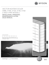
Electronic Expansion Valves (EEV)
Electronic expansion valves differ to the normal thermostatic expansion valves in their ability to
maintain control of the suction superheat at reduced head pressures. This can lead to signicant
energy savings particularly at reduced loading and low ambient temperatures.
EEV step position, superheat setpoint, head pressure set point and other features can be viewed and
adjusted via the microprocessor display.
Whilst offering versatile control at the full design duty of the unit, Thermostatic Expansion
Valve’s (TEV) do not automatically optimise themselves to all operating conditions.
Therefore, if the refrigeration system is operating at 40% or 50% of full load, especially
at a lower ambient temperature than that for which the valve was sized, the conventional TEV must
have the design head pressure available to ensure good refrigerant control. Maintaining an
articially high condensing pressure is normal in conventional systems.
Using an EEV allows for good refrigeration control whilst operating at part load and lower ambient
conditions with a reduced condensing pressure. By tting an EEV and adjusting the head pressure
control setting an increase in the system EER (Energy Efciency Ratio) of up to 30% can typically
be seen. The Mollier diagram shown below helps to illustrate how this increase in efciency is
achieved.
EEVs differ from thermostatic expansion valves in their ability to maintain control of refrigerant ow and suction
superheat at reduced head pressures. The turn-down rate of a typical EEV is superior to that of it’s thermostatic
equivalent, such that a reduced optimum condensing pressure can be maintained at low compressor load. However
low the load is on the compressor, from 0 to 100%, there will not be a problem with turndown, even down to 10% of the
valve's rated capacity.
Heat of Rejection
Reduction in
Compressor Input
Power
Enthalpy kJ/kgIncrease in
Cooling Duty
Evaporating
Pressure
Reduced
Condensing
Pressure
Pressure
Bara
Thermostatic Expansion Valve (1)
Electronic Expansion Valve (2)
1
2
3
4
Key:
(1) Cooling Cycle @ 22°C ambient with a conventional TEV tted.
(2) Cooling Cycle @ 22°C ambient, showing a typical EEV condensing temperature taking full advantage of lower
ambient air temperatures (below 35°C).
SmartCool™ 60 - 140kW DX Precision Air Conditioning
20
Introduction
SmartCool 60 - 140kW Direct Expansion Technical Manual 7968969 V1.13_10_2020
Page is loading ...
Page is loading ...
Page is loading ...
Page is loading ...
Page is loading ...
Page is loading ...
Page is loading ...
Page is loading ...
Page is loading ...
Page is loading ...
Page is loading ...
Page is loading ...
Page is loading ...
Page is loading ...
Page is loading ...
Page is loading ...
Page is loading ...
Page is loading ...
Page is loading ...
Page is loading ...
Page is loading ...
Page is loading ...
Page is loading ...
Page is loading ...
Page is loading ...
Page is loading ...
Page is loading ...
Page is loading ...
Page is loading ...
Page is loading ...
Page is loading ...
Page is loading ...
Page is loading ...
Page is loading ...
Page is loading ...
Page is loading ...
Page is loading ...
Page is loading ...
Page is loading ...
Page is loading ...
Page is loading ...
Page is loading ...
Page is loading ...
Page is loading ...
Page is loading ...
Page is loading ...
Page is loading ...
Page is loading ...
Page is loading ...
Page is loading ...
Page is loading ...
Page is loading ...
Page is loading ...
Page is loading ...
Page is loading ...
Page is loading ...
Page is loading ...
Page is loading ...
Page is loading ...
Page is loading ...
Page is loading ...
Page is loading ...
Page is loading ...
Page is loading ...
Page is loading ...
Page is loading ...
Page is loading ...
Page is loading ...
Page is loading ...
Page is loading ...
Page is loading ...
Page is loading ...
Page is loading ...
Page is loading ...
Page is loading ...
Page is loading ...
Page is loading ...
Page is loading ...
Page is loading ...
Page is loading ...
Page is loading ...
Page is loading ...
Page is loading ...
Page is loading ...
Page is loading ...
Page is loading ...
Page is loading ...
Page is loading ...
Page is loading ...
Page is loading ...
Page is loading ...
Page is loading ...
Page is loading ...
Page is loading ...
Page is loading ...
Page is loading ...
Page is loading ...
Page is loading ...
Page is loading ...
Page is loading ...
Page is loading ...
Page is loading ...
Page is loading ...
Page is loading ...
Page is loading ...
Page is loading ...
Page is loading ...
Page is loading ...
Page is loading ...
Page is loading ...
Page is loading ...
Page is loading ...
Page is loading ...
Page is loading ...
Page is loading ...
Page is loading ...
Page is loading ...
Page is loading ...
Page is loading ...
Page is loading ...
Page is loading ...
Page is loading ...
Page is loading ...
Page is loading ...
Page is loading ...
Page is loading ...
Page is loading ...
Page is loading ...
Page is loading ...
Page is loading ...
Page is loading ...
Page is loading ...
Page is loading ...
Page is loading ...
Page is loading ...
Page is loading ...
Page is loading ...
Page is loading ...
Page is loading ...
Page is loading ...
Page is loading ...
Page is loading ...
Page is loading ...
Page is loading ...
Page is loading ...
Page is loading ...
Page is loading ...
Page is loading ...
Page is loading ...
Page is loading ...
Page is loading ...
Page is loading ...
Page is loading ...
Page is loading ...
Page is loading ...
Page is loading ...
Page is loading ...
Page is loading ...
Page is loading ...
Page is loading ...
Page is loading ...
Page is loading ...
Page is loading ...
Page is loading ...
Page is loading ...
Page is loading ...
Page is loading ...
Page is loading ...
Page is loading ...
Page is loading ...
Page is loading ...
Page is loading ...
/