Hamworthy Purewell Variheat mk2 Owner's manual
- Type
- Owner's manual

Purewell Variheat mk2 c Boilers
Cast Iron, Pre-mix, Condensing, Modular Boilers with
Automatic Ignition for Heating and Domestic Hot Water
Installations
Installation, Commissioning
and Servicing Instructions
MODELS - 70c, 95c, 110c, 140c & 180c
NATURAL GAS
I
2H
IMPORTANT NOTE
THESE INSTRUCTIONS MUST BE READ
AND UNDERSTOOD BEFORE INSTALLING,
COMMISSIONING, OPERATING OR
SERVICING EQUIPMENT

Customer After Sales Services
Telephone: 01202 662555 Email: service@hamworthy-heating.com Fax: 01202 662522
Technical Enquiries
To supplement the detailed technical brochures, technical advice on the application and use in the Hamworthy Heating range
is available from our technical team in Poole and our accredited agents.
Site Assembly
Hamworthy offer a service if site assembly for many of our products where plant room access is restricted. Using our trained
staff we offer a high quality of build and assurance of a boiler built and tested by the manufacturer.
Commissioning
Commissioning of equipment by our own engineers, accredited agents or specialist sub-contractors will ensure the equipment
is operating safely and efficiently.
Service Contracts
Regular routine servicing of equipment by Hamworthy service engineers inspects the safety and integrity of the plant, reducing
the risk of failure and improving performance and efficiency. Service contracts enable you to plan and budget more efficiently.
Breakdown service, repair, replacement
Hamworthy provide a rapid response breakdown, repair or replacement service through head office at Poole and accredited
agents throughout the UK.
Spare Parts
We offer a comprehensive range if spare parts, providing replacement parts for both current and discontinued products.
Delivery options are available to suit you. Please refer to our website fir more details.

HAMWORTHY HEATING LTD
Page
PUREWELL Variheat mk2
218612 A03
1
i
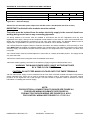
NOTE: THESE INSTRUCTIONS MUST BE READ AND UNDERSTOOD BEFORE
INSTALLING, COMMISSIONING, OPERATING OR SERVICING EQUIPMENT.
THE PUREWELL BOILER IS INTENDED FOR USE AS A COMMERCIAL APPLIANCE AND IS
NOT CERTIFIED FOR USE IN DOMESTIC APPLICATIONS.
THIS BOILER IS FOR USE ON GROUP H NATURAL GAS (2ND FAMILY) I2H PLEASE
ENSURE RELEVANT INFORMATION REQUIRED WITHIN DOCUMENT IS FOUND
BEFORE FIRING BOILER.
COUNTRY OF DESTINATION : UNITED KINGDOM & REPUBLIC OF IRELAND
THIS BOILER COMPLIES WITH ALL RELEVANT EUROPEAN DIRECTIVES.
PRODUCT IDENTIFICATION No. 86CN70
PUBLICATION NO. 218612
ISSUE ‘A03’
12/2018
Purewell Variheat mk2 c Boilers
Cast Iron, Pre-mix, Condensing, Modular Boilers with
Automatic Ignition for Heating and Domestic Hot Water
Installations
Installation, Commissioning
and Servicing Instructions
MODELS - 70c, 95c, 110c, 140c & 180c
NATURAL GAS
I
2H

HAMWORTHY HEATING LTD
Page
PUREWELL Variheat mk2
218612 A03
2
ii
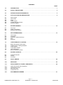
CONTENTS
PAGE
1.0 INTRODUCTION ................................................................................................................................ 1
2.0 SUPPLY AND DELIVERY ................................................................................................................. 2
3.0 SIZE AND SPACE REQUIREMENTS ............................................................................................... 4
4.0 SITE LOCATION AND PREPARATION ............................................................................................ 6
4.1 Site Location
4.2 Gas Supply
4.3 Flues
4.4 Water Supply
4.5 Condensate Connections
4.6 Electrical Supply
5.0 BOILER ASSEMBLY ....................................................................................................................... 12
5.1 Flue Pipe
5.2 Water Connections
5.3 Electrical Connections
6.0 PRE-COMMISSIONING ................................................................................................................... 13
6.1 Gas Supply
6.2 Ventilation
6.3 Pipework, Valves and Pump
6.4 Flue
6.5 Electrical
7.0 CHECKS PRIOR TO LIGHTING ...................................................................................................... 14
7.1 Boiler Gas System Leak Check
7.2 Checks Prior to Lighting the Boiler
7.3 Initial Lighting
7.4 Combustion Checks
7.6 User Instructions
7.7 Burner Resistance Check
8.0 BOILER CONTROLS ....................................................................................................................... 22
8.1 Controls Overview
8.2 Display
8.3 Functions
9.0 FAULT FINDING .............................................................................................................................. 26
10.0 SERVICING ...................................................................................................................................... 26
11.0 REPLACEMENT OF FAILED COMPONENTS ............................................................................... 28
11.1 Igniter and Flame Probe Assembly
11.2 Temperature Limiter
11.3 Main Gas Valve
11.4 Combustion Fan
12.0 RECOMMENDED SPARES ............................................................................................................. 37

HAMWORTHY HEATING LTD
Page
PUREWELL Variheat mk2
218612 A03
3
iii
PAGE
APPENDICES
APPENDIX A GAS DATA ............................................................................................................................. 38
APPENDIX B ELECTRICAL CONNECTIONS AND CONTROLS ............................................................... 39
APPENDIX C FLUE DATA ........................................................................................................................... 41
APPENDIX D VENTILATION........................................................................................................................ 44
APPENDIX E WATER DATA ....................................................................................................................... 45
APPENDIX F ADDITIONAL KITS ................................................................................................................ 50

HAMWORTHY HEATING LTD
1
PUREWELL Variheat mk2
218612 A03
1.0 INTRODUCTION
1.1 A competent person holding ‘GAS SAFE’
registration or equivalent must install this boiler. All
installations MUST conform to the relevant Gas
Safety and Building Regulations. Health & Safety
requirements must also be taken into account when
installing any equipment. Failure to comply with the
above may lead to prosecution.
This appliance is not intended for use by persons
(including children) with reduced physical, sensory or
mental capabilities, or lack of experience and
knowledge, unless they have been given supervision
or instructions concerning cleaning, maintenance and
use of the appliance by a person responsible for their
safety. Children should be supervised to ensure that
they do not play with the appliance.
1.2 These instructions are for Group H Natural Gas
(2nd Family) only. The information relating to Natural
Gas firing is to be found in Appendix ‘A’. Boilers MUST
NOT use gas other than that for which they were
designed and made.
1.3 The Purewell Variheat mk2 is a fully modulating,
pre-mix condensing, gas fired boiler manufactured
from horizontal cast iron heat exchanger sections,
connected to an economiser located in the base of
the boiler. The boiler is floor mounted and is intended
for the heating of Commercial and Industrial
premises. It may also be used to supply hot water for
these premises via an indirect cylinder.
1.3.1 Operation is initiated and controlled by a Navistem
boiler management system with a user interface LCD
display for accessing and changing boiler parameters.
1.3.2 The Purewell Variheat mk2 boiler is delivered to
site fully assembled fitted with it’s casing and
controls. Care should be taken when manoeuvring
the boiler into position to avoid damage.
1.3.3 Each of the boiler models is designed for direct
connection to a flue system. The flue system must be
suitable for pressurised wet operation. The flue
outlets from more than one unit may be connected to
a single chimney. No draught diverter is fitted to the
boiler nor is a fixed diverter required in the flue
system. However a draught stabiliser is
recommended for some installations —see Appendix
‘C’ (Page 41).
1.3.4 The Purewell Variheat mk2 has a low water
content and minimum flow rates MUST be maintained
above the recommended levels shown in Appendix
‘E’ (Page 45).
1.4 If the boiler is to be connected to an un-vented
(pressurised) heating system, care must be taken to
ensure all extra safety requirements are met and that
the relevant interlocks will shut down the boiler(s)
should a high or low pressure fault occur.
The pressurisation unit must also incorporate a low
level water switch, which protects the water pumps,
and will directly or indirectly shut down the boiler
plant should a low water condition occur.
Consideration should also be given to the maximum
working pressure of the boiler as per Appendix ‘E’.
Consult Hamworthy Heating Technical Department
for help or assistance if in doubt.
1.5 The Purewell Variheat mk2 boiler is not suitable
for direct connection to domestic hot water supplies
or gravity fed heating systems.
1.6 The Purewell Variheat mk2 boiler can be installed
with either reverse return water flow layout or with
single pipe header layout (non HHL supply). See
Appendix E for typical schematic layout.
1.7 It is good practice in all heating installations to
use some form of water treatment to reduce
formation of lime scale and black iron oxide sludge.
The high efficiencies produced by the Purewell
Variheat mk2 Boiler can easily be reduced by lime
scale formation. If a pressurisation unit is used, it is
prudent to include an hours run meter to give an
indication of pump running time and hence raw water
make-up. Any leaks should be attended to as soon as
possible to avoid scale build up within the boiler's
waterways.
1.8 Each Purewell Variheat mk2 module is supplied
with volt free contact outputs for Normal Run, Boiler
lock-out from a General Fault, 0~10v analogue
control input. Also provided are connections for BMS,
Shunt Pump & Remote On/Off control as well as
connections to a boiler lock circuit (causing the boiler
to go to standby).
1.9 Options
1.9.1 Optional reverse return header kits are
available in 2, 3 & 4 boiler configuration covering
models 70c, 95c, 110c, 140c & 180c. These kits
incorporate all necessary valves and interconnecting
pipework. Refer to individual kit instructions for
details.
1.9.2 Controls peripherals
The Navistem boiler management system has the
potential to accept the following control options:
1.9.3 OCI345 LPB Clipin – Kit part number: 563605667
BSB to LPB interface to allow communication between
boilers for Cascade of 16 boilers by LMS or
communication to external RVS system components
(e.g. Merley sequence controller).
1.9.4 For additional kit information please refer to
Appendix F (page 50).

HAMWORTHY HEATING LTD
2
PUREWELL Variheat mk2
218612 A03
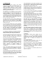
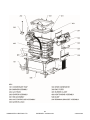
2.0 SUPPLY AND DELIVERY
Your boiler is despatched to site as a pre-assembled and tested unit. It is the installers responsibility to convey the
boiler to the plantroom.
Ensure the boiler is kept secure when handling to avoid it toppling, as this will result in damage.
The flue connection & condensate trap to the boiler are packaged separately to avoid damage. The flue
components consist of an adaptor elbow, gasket and straight length of 150mm diameter flue pipe. The condensate
trap is supplied loose within the boiler’s inner packaging.
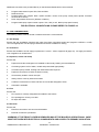
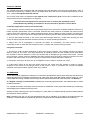
TRANSPORTING & POSITIONING OF THE BOILER
CAUTION: Risk of injury through carrying heavy loads.
Only trained personnel may undertake the handling.
A risk assessment must be undertaken, taking into
account each installations variabilities.
Observe safety instructions relating to the lifting of
heavy loads.
Protect the boiler against slippage by means of a
transport strap.
NOTICE: Boiler damage through impact.
The standard delivery of the boiler includes
components that are susceptible to impact damage.
Protect all components against impact influences
when transporting the boiler.
Observe the transport instructions on the
packaging.
Where possible, transport the boiler to the installation
location in its shipping packaging to protect it from
contamination and damage.
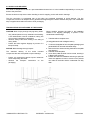
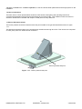
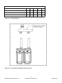
1. Take the boiler to the plant room..
(*If using pallet truck refer to diagram below.)
2. To remove the appliance from the pallet, packaging and
panels MUST be removed and stored safely.
3. Remove the four screws securing the boiler to the pallet
(see diagram.)
4. Take the unit off the pallet.
5. Once off the pallet the boiler can be moved, ensuring it
is lifted on the sump ribs.
6. Position the boiler for installation and using a sprit level
check the appliance is level to ensure no air pockets
can collect in the boiler and the condensate can fully
drain.

HAMWORTHY HEATING LTD
3
PUREWELL Variheat mk2
218612 A03
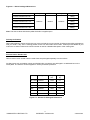
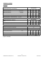
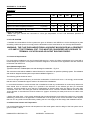
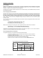
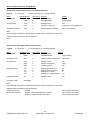
Model Depth Width Height Weight
Purewell Variheat mk2 70c
1200mm 800mm
195kg
Purewell Variheat mk2 95c 195kg
Purewell Variheat mk2 110c 195kg
Purewell Variheat mk2 140c 250kg
Purewell Variheat mk2 180c 250kg
1320mm
Figure 2.1 - Boiler Packaged Dimensions
Delivery Verification
When taking delivery please ensure that you have received the correct number of boilers and ancillary packages to
fulfil your order. If any item is missing please contact our after sales service team. Please provide details of your
order such as order number and contract number as well as a detailed description of the missing item.
Reverse Return Header Sets
Where reverse return header sets are used these are packaged separately from the boilers.
Ancillary items such as isolation valves and flexible boiler connectors are packaged in a cardboard box on the
same pallet. The whole is shrink wrapped for security and basic protection.
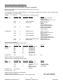
Model Configuration Length
mm
Weight
kg
70c -140c 2 boilers 1168 57
70c -140c 3 boilers 1730 95
70c -140c 4 boilers 2336 133
180c 2 boilers 1250 112
180c 3 boilers 1784 178
180c 4 boilers 2318 300
Figure 2.2 - Header Kit Packaged Dimensions
Note: The above values include the pallet the boiler is supplied upon.

HAMWORTHY HEATING LTD
4
PUREWELL Variheat mk2
218612 A03
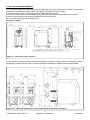
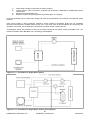
3.0 SIZE AND SPACE REQUIREMENTS
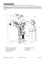
3.1 The Purewell Variheat mk2 boiler range has been designed to utilise minimum floor space, therefore it is important the
plantroom has sufficient ceiling height to allow for installation and connection to the flue system.
A minimum distance of 50mm must be maintained from easily flammable materials
Also important is allowance for sufficient access at front, sides and rear of boiler for flue and pipework connections.
Ensure a minimum height of 150mm above the boiler for removal of the covers.
Do not run cabling through the top or display covers.
See Figure 3.1 below.
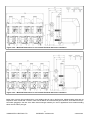
3.2 The Hamworthy Heating Ltd water manifold kit is designed to provide a compact solution for connecting the boilers to
the gas supply and flow and return water connections. (Refer to the Manifold Kit Installer’s Guide for specific details.)
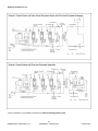
Figure 3.1 - Dimensions and Clearances
Figure 3.2.1 – Manifold Dimensions for a 2 Purewell Variheat mk2 boiler installation

HAMWORTHY HEATING LTD
5
PUREWELL Variheat mk2
218612 A03
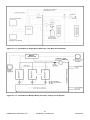
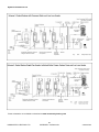
Figure 3.2.3 – Manifold Dimensions for a 4 Purewell Variheat mk2 boiler installation
Figure 3.2.2 – Manifold Dimensions for a 3 Purewell Variheat mk2 boiler installation
Safety Valve: As each kit is provided with a 3 port isolating valve for use on the flow pipe, individual safety valves are not
required on each module and a common valve can be fitted in the combined flow pipe. However, each boiler has a Rp1”
connection (plugged) in the rear of the boiler heat exchanger assembly for use on applications where module isolating
valves are not of the 3 port type..

HAMWORTHY HEATING LTD
6
PUREWELL Variheat mk2
218612 A03
4.0 SITE LOCATION AND PREPARATION
4.1 Site Location.
The floor or plinth for the boilers and water manifold kit must be both flat and level to ensure correct alignment of
fittings and connections.
The floor or plinth must be sufficiently strong to support the weight of both the boilers and manifold kit where used.
The floor or plinth must be fireproof in accordance with BS 6644.
The plantroom must have sufficient space for installation of boilers, manifold kits, pipework, pumps controls, flues
ventilation, access and servicing and other items of plant.
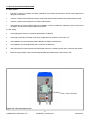
4.2 Gas Supply.
Gas supply pipes must be in accordance with BS 6891 or IGE/UP/2
Gas supply connection to the boiler must not be smaller than the connection on the boiler - R1”
Gas installation must be soundness tested to BS 6891 or IGE/UP/1 & IGE/UP/1A.
Gas installation must be purged to BS 6891 or IGE/UP/1 & IGE/UP/1A.
Inlet gas pressure to boiler should be nominal 20mbar (minimum 17.5mbar) dynamic at the connection to the boiler.
Boiler house gas isolation valve must be clearly identified and installed close to the entrance / exit.
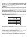
R 1” Gas Connection
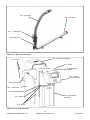
Figure 4.2 – Gas Connection Point

HAMWORTHY HEATING LTD
7
PUREWELL Variheat mk2
218612 A03
4.3 Flues
Flue termination, routing and construction must comply with the requirements of the Clean Air Act 1993—Chimney
Memorandum, BS 6644 BS 5440 and IGE/UP/10.
Any flue must be self supporting and separable from the boiler for servicing requirements.
The maximum number of modules firing into a common chimney is 9. For larger installations refer to HHL Technical.
Due to the low flue gas temperature, 50°C (condensing) - 75°C (non-condensing), condensation will occur in the flue,
flue materials must be non-corrosive and utilise fully sealing joints.
Flue construction is recommended of a twin wall, insulated type to maintain buoyancy within the flue.
Adequate facilities must be provided for draining the flue condensation.
Horizontal flue runs must be kept as short as possible and be inclined at minimum 2° towards the termination.
The flue system must be designed acknowledging that there may be a positive pressure generated by the boiler
combustion fan. Refer to Appendix C.
The flue system must be designed to limit the max. suction (cold) to 30Pa negative, measured at the connection to
the boiler. If the suction is greater than 30Pa, refer to HHL Technical.
This condition must then be checked hot and with all boilers firing, the max. pressure at the connection to
the boiler should be 100Pa positive.
In the event that the flue system when hot does generate a suction, the max. suction is 100Pa.
Any stabiliser fitted must be in or close to the vertical chimney.
Fan dilution - the design must provide for the use of balancing and trim dampers, and their location and
operation must be such that the constraints detailed above can be met. Care must be taken to ensure that
the fan performance is matched to deliver the appropriate dilution, whilst ensuring that the excessive suction
is not applied to the boilers. If in doubt, refer to HHL Technical.
Fan assist - the use of fan assist must only be a last resort, as the boilers have sufficient fan performance to
drive the system. If in doubt, refer to HHL Technical.
Connecting flue systems may be smaller in internal diameter than the boiler connection and must be
designed to deliver the necessary condition at the connection to the boiler. Refer to Hamworthy Heating
Technical dept. for assistance.

HAMWORTHY HEATING LTD
8
PUREWELL Variheat mk2
218612 A03
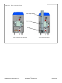
Figure 4.3 – Flue Connection Point
Flue Connection as delivered Flue Connection fitted
Flue fixing bracket
Flue Pipe
Elbow

HAMWORTHY HEATING LTD
9
PUREWELL Variheat mk2
218612 A03
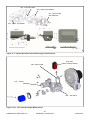
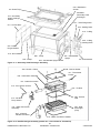
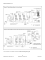
Figure 4.4 – Water Connection Points
4.4 Water Supply
Feed and Expansion tanks to comply with static height requirements of BS6880 & BS6644.
Cold feed and open vent pipes to comply with requirements of BS 6644.
Pressurised system to comply with BS 7074.
It is recommended that the system pipework is flushed twice before water treatment.
In hard water areas (>180mg CaCO3/litre) precautions such as water treatment are strongly recommended to
prevent the build up of sludge and scale and also to control the system water pH to between 7.0 & 8.0.
Leaks in the system pipe work should be fixed to prevent dilution of water treatment.
Maximum working water pressure is 6 bar.
For minimum water pressure see Appendix ‘E’ - Water Data (Page 45)
Flow Connection
Return Connection
Model Type
PV70c, 95c & 110c Model Type
PV140c & 180c

HAMWORTHY HEATING LTD
10
PUREWELL Variheat mk2
218612 A03
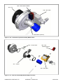
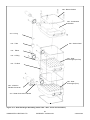
Figure 4.5.2 – Boiler Condensate Connection
4.5 Condensate Connections
Provision must be made for removal of condensate from the boiler and flue system.
Condense is mildly acidic, typically pH 3 - pH 5.
Condense pipework must be non-corrosive and not copper. Hamworthy recommend 32mm dia. Plastic waste
pipe.
Condense may be discharged to a standard drain subject to National or Local regulations.
Boiler Condensate
Connection
(32mm o/d)
Figure 4.5.1 - Boiler Condensate Pipework Connection
Location of condense pipework
should prevent freezing within
tundishes, traps and pipework.
Do not allow blockage or
damage to the condensate trap.
The connection to the boiler
condense drain accepts a
straight push-fit coupling for
32mm i.d. plastic waste pipe.

HAMWORTHY HEATING LTD
11
PUREWELL Variheat mk2
218612 A03
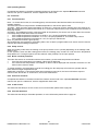
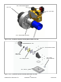
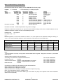
Figure 4.6 - Electrical Connections
4.6 ELECTRICAL SUPPLY
WARNING! THIS APPLIANCE MUST BE EARTHED IN ACCORDANCE WITH IEE REGULATIONS
Boiler electrical supplies must not be switched by a time clock.
Boilers are suitable for 230Volt, 50Hz supply.
External fuses should be rated for 10 amps
Wiring must be completed in heat resistant cable size 1.0mm² csa.
Each module should have individual means of isolation.
Electrical isolators must facilitate complete electrical isolation.
Electrical isolators must have contact separation of minimum 3mm in all poles.
Electrical isolators must be installed in readily accessible locations.
Electrical supplies to boiler modules should only serve the boiler.
Where volt free contacts are used, these too must be individually isolatable.
Time clock control should be via the boiler modules Remote On/Off circuit (5V DC).
Any circuit connected to the Remote On/Off MUST be volt free and compatible.
ADDITIONAL INFORMATION REGARDING ELECTRICAL SUPPLIES IS GIVEN IN BS
EN60335, Part 1.
NOTE: The appliance MUST be isolated from the electrical supply if electric arc welding
is carried out on connecting pipework.
FOR DETAILED WIRING INSTRUCTIONS SEE SECTIONS 5.3, 9.0 & APPENDIX B

HAMWORTHY HEATING LTD
12
PUREWELL Variheat mk2
218612 A03
Open Vented Systems
Boilers must not be capable of isolation from the vent pipe. Valves between boiler and vent pipe to be three way
type such that when boiler is isolated from vent pipe it is open to atmosphere. Safety valves should either be
mounted on the boiler by using the connection provided, or it should not be possible to isolate a safety valve
common to more than one boiler from each boiler. BS6644 provides details.
Sealed Systems
A boiler must not be capable of isolation from the individual or common safety valve. Valves between boiler and
common safety valve to be three way type such that when boiler is isolated from safety valve it is open to
atmosphere. The boiler is provided with a connection on the boiler for the safety valve .
Where using Hamworthy Heating Ltd pipework kits, assembly of these is detailed in the Instruction manual
supplied with kit.
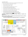
5.3 Electrical Connections:
The following electrical connections are provided on each module on a rail at the base of the front of the boiler.
Supply: Live, Neutral and Earth. See Section 4.6 for details.
Live and Neutral connections for Shunt pump or Primary Pump
Boiler Overheat Fault Alarm Signal Output
Common Fault Alarm Signal Output
Boiler Normal Run Signal Output
Remote On/Off
0-10v Analogue Control Signal Input
Outside Temperature sensor
LPB Bus Connection (Option)
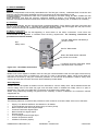
5.0 BOILER ASSEMBLY
General
Boilers are despatched to site as fully assembled units. The flue pipe, chimney, condensate drain connection and
pipework manifold set (where applicable) are the only items that will need assembling on site.
During assembly it is important to take care to prevent damage to the boiler casing. DO NOT STAND ON THE
CASING PANELS.
Boiler positioning must allow the minimum clearances detailed in Section 3.0 to facilitate access for flue and
pipework connections as well as maintenance. Boilers can be positioned side by side, no clearance is necessary.
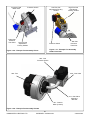
5.1 Flue Pipe
So as to avoid damage, the flue connecting pipe is supplied separately. Fit the elbow to the base of the boiler and
secure using the gasket and 6 - M8 bolts and washers. Moisten the lip seal and engage the flue pipe into the
elbow. Secure the flue pipe to the boiler casing using the bracket supplied.
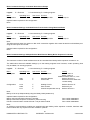
5.2 Water Connections:
Connecting pipework must be self-supporting to avoid stress on the boiler connections. Local unions are
recommended in the pipework to facilitate future servicing requirements. The following connections are
provided on each boiler module;
Figure 5.2.1 - Rear Water Connections
Rp1”
Safety Valve
Flow R2” Male thread. Indicated by a
red dot on boiler.
Return R2” Male thread. Indicated
by a blue dot on boiler.
Gas R1” Male thread.
Condense 32mm dia. Male plain. Offset
and below return connection.

HAMWORTHY HEATING LTD
13
PUREWELL Variheat mk2
218612 A03
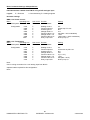
Additional connections are provided directly on the Navistem B3000 boiler control module:
Programmable sensor inputs. BX1, BX2 and BX3
DHW sensor B3
Programmable relay outputs. QX2—(DHW circulator / direct circuit pump control) QX3—(Boiler circulator/
Shut off valve control)
Room temperature sensors X7 (QAA55 or QAA74)
Programmable pump speed control outputs. UX2, UX3 (0-10V, Boiler pump speed control)
FOR ELCTRICAL CONNECTIONS PLEASE REFER TO FIGURE 4.6
6.0 PRE-COMMISSIONING
The following checks must be carried out before the boiler is commissioned.
6.1 Gas Supply.
Ensure that gas installation pipework and meter have been soundness tested and purged to IGE/UP/1 or IGE/
UP/1A as appropriate. Test and purge certificates should be available for viewing.
6.2 Ventilation
Ensure that ventilation and air supply to plantroom is correct - refer to Appendix D (page 44). Air supply around the
rear of appliance is unobstructed.
6.3 Pipework, Valves and Pump
Ensure that;
Pipework and valve arrangement is installed to Hamworthy Heating recommendations.
Circulating system is full of water, vented and pressurised appropriately.
Circulation pump is fitted, working and interlocked where required.
Pipework connections to boiler are fitted correctly.
All necessary isolation valves are open.
Safety valve is correctly sized and located.
Condense connections on boiler and flue are connected and piped to drain.
Heat load is available.
6.4 Flue
Ensure that;
Flue system is correctly designed and installed to suit boilers.
Flue passages to chimney are clear.
Fill traps with water.
6.5 Electrical
Ensure that;
Electrical connections are correct and isolatable.
External controls are operational.
WARNING: IF THE FRONT COVER IS REMOVED WHILST THE BOILER IS OPERATIONAL, CARE
MUST BE TAKEN WITH ELECTRICAL COMPONENTS AND ACCESS TO PRIMARY INSULATION.

HAMWORTHY HEATING LTD
14
PUREWELL Variheat mk2
218612 A03
7.0 CHECKS PRIOR TO LIGHTING
IMPORTANT: BEFORE PROCEEDING TO LIGHT THE BOILER, ENSURE THAT THE PRE-
COMMISSIONING CHECKS HAVE BEEN CARRIED OUT AND THE RESULTS SATISFACTORY.
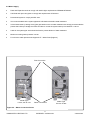
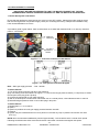
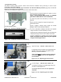
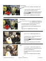
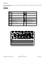
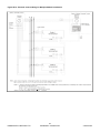
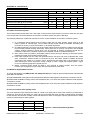
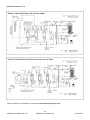
7.1 Boiler Gas System Leak Check
Ensure that the appliance manual gas service valve is in the OFF position. Although the boiler receives a gas
leak check and gas train component integrity check prior to leaving the factory, transport and installation may
have caused disturbance to unions.
A procedure guide is given below. Care must be taken not to allow leak detection fluid on or near any electrical
parts or connections.
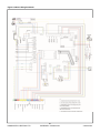
Figure 7.1.2 - Gas System Leak Check Diagram
Note: - Main gas supply pressure - G20 - 20mbar
To Check Valve B
1) Turn off the electrical power and gas to the appliance.
2) By unscrewing screw at Position X of Figure 7.1.1 remove the red gas pressure switch (L.H.S picture) or loosen
the test point valve plug (R.H.S picture).
3) Connect the manometer to gas valve test point.
4) With A, B closed open C and monitor manometer over a 2 minute period, a rise indicates a leak on valve B.
5) Reinstall red gas pressure switch or shut valve plug in test point.
To Check Valve A
1) Repeat steps 1, 2, 3 & 5 above.
2) Open C.
3) Open B to produce the main gas supply pressure between A and B.
4) Close B
5) System may be considered sound if over a period of 2 minutes any drop in pressure is less than 0.5 mbar
(0.2" wg.).
NOTE: Allow a manometer stabilisation period of approximately 1-minute before each 2 minute check period.
Following soundness tests close valve B and remove manometer connections and tighten test points.
Figure 7.1.1 - Test Point Locations On Gas Valves
Position X
(Test Point)
Low Gas
Pressure
Switch

HAMWORTHY HEATING LTD
15
PUREWELL Variheat mk2
218612 A03
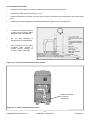
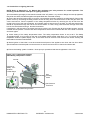
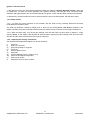
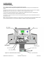
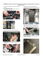
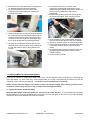
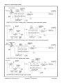
7.2 Checks Prior to lighting the boiler
NOTE: Refer to Appendix A for Natural Gas maximum gas inlet pressure for normal operation. The
following checks must be made prior to lighting the boiler.
1) Ensure that the gas supply is connected but turned to the "off" position. Any unions or fittings are correctly tightened,
test points are closed, and that the ignition and probe leads are connected correctly.
2) Ensure the electrical mains supply is correctly connected but the boiler isolator(s) are switched off. Remove the
plastic covers by unscrewing the fixing screws. Check all wiring loom connections such as fan and gas valve, are
correct and secure. Test the operation of the safety temperature limiter by removing the clip & bulb from the
pocket in the front of the heat exchanger, and carefully apply a heat source to the bulb. The limit stat reset button
should lift & protrude through the hole in the controls fascia. To reset, firmly press the button through the access
hole in the controls fascia using a terminal screwdriver.
If satisfactory, refit the bulb in the pocket and secure with the clip. Ensure that all limiter bulbs /sensors are fully
inserted into the pockets. The flow and return temperature sensors are located at the rear of the boiler in the flow
and return pipes.
3) Check setting of the safety temperature limiter. The safety temperature limiter is set at 95°C. The Safety
Temperature limiter, is to be found on the rear of the display fascia bracket. (See figure 7.2.1) To remove the safety
temperature limiter the plastic display cover of the boiler must be removed. Then unscrew the screws securing the
thermostat on the metal control bracket.
4) Before ignition of the boiler it must be ensured that all parts of the appliance are clean and free from debris.
Special attention should be paid to ensure that the air inlet to the fan/venturi is clean and unobstructed.
5) Ensure the heating system circulation / shunt pump is operational and that the pipework is free of air.
Figure 7.2.1 Location Gas Isolating
Valve/Safety Temperature Limiter
Gas
Isolating
Valve
Gas Pressure
Test Point
Position Of
Safety Tem-
perature
Limiter Reset
Air Inlet
Location of Thermostat Fixing Screws
Page is loading ...
Page is loading ...
Page is loading ...
Page is loading ...
Page is loading ...
Page is loading ...
Page is loading ...
Page is loading ...
Page is loading ...
Page is loading ...
Page is loading ...
Page is loading ...
Page is loading ...
Page is loading ...
Page is loading ...
Page is loading ...
Page is loading ...
Page is loading ...
Page is loading ...
Page is loading ...
Page is loading ...
Page is loading ...
Page is loading ...
Page is loading ...
Page is loading ...
Page is loading ...
Page is loading ...
Page is loading ...
Page is loading ...
Page is loading ...
Page is loading ...
Page is loading ...
Page is loading ...
Page is loading ...
Page is loading ...
Page is loading ...
Page is loading ...
Page is loading ...
Page is loading ...
Page is loading ...
Page is loading ...
Page is loading ...
Page is loading ...
Page is loading ...
Page is loading ...
Page is loading ...
Page is loading ...
Page is loading ...
Page is loading ...
Page is loading ...
Page is loading ...
Page is loading ...
-
 1
1
-
 2
2
-
 3
3
-
 4
4
-
 5
5
-
 6
6
-
 7
7
-
 8
8
-
 9
9
-
 10
10
-
 11
11
-
 12
12
-
 13
13
-
 14
14
-
 15
15
-
 16
16
-
 17
17
-
 18
18
-
 19
19
-
 20
20
-
 21
21
-
 22
22
-
 23
23
-
 24
24
-
 25
25
-
 26
26
-
 27
27
-
 28
28
-
 29
29
-
 30
30
-
 31
31
-
 32
32
-
 33
33
-
 34
34
-
 35
35
-
 36
36
-
 37
37
-
 38
38
-
 39
39
-
 40
40
-
 41
41
-
 42
42
-
 43
43
-
 44
44
-
 45
45
-
 46
46
-
 47
47
-
 48
48
-
 49
49
-
 50
50
-
 51
51
-
 52
52
-
 53
53
-
 54
54
-
 55
55
-
 56
56
-
 57
57
-
 58
58
-
 59
59
-
 60
60
-
 61
61
-
 62
62
-
 63
63
-
 64
64
-
 65
65
-
 66
66
-
 67
67
-
 68
68
-
 69
69
-
 70
70
-
 71
71
-
 72
72


Hamworthy Purewell Variheat mk2 Owner's manual
- Type
- Owner's manual
Ask a question and I''ll find the answer in the document
Finding information in a document is now easier with AI
Related papers
-
Hamworthy Purewell Installation guide
-
Hamworthy Purewell VariHeat condensing Installation guide
-
-
-
-
-
-
-
-
Other documents
-
Garth Manifold Operating instructions
-
Calorex Variheat AA/AW Series Installation guide
-
-
-
Ideal Boilers Concord CXSD 50/H Installation & Servicing Manual
-
ESBE 90C Complete Operating instructions
-
 airmaster CC 800 User manual
-
ACV EVO S Operating instructions
-
Slant/Fin VICTORY II VHS Series Application Manual
-
Keston Heat 2 Installation guide
