Page is loading ...

NOTE: DIAGRAMS & ILLUSTRATIONS ARE NOT TO SCALE.
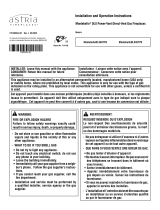
NOTICE
• READ ALL STEPS BEFORE STARTING INSTALLATION.
• LEAVE THESE INSTRUCTIONS WITH THE APPLIANCE.
• All warnings, precautions, and instructions in the Installation and
Operation Instructions provided with the appliance also apply to
these instructions.
• If you encounter any problems, need clarification of these
instructions, or are not qualified to properly install this kit, contact
your local distributor or dealer.
HEARTH PRODUCTS
KITS AND ACCESSORIES
POWER VENT KIT
MODEL LPVK-110
INSTALLATION INSTRUCTIONS FOR POWER VENT KIT MODEL LPVK-110 (CAT. NO. H7387)
FOR USE WITH ELECTRONIC, DIRECT-VENT GAS FIREPLACES LISTED IN TABLE 2
Report No. 14-108
GENERAL INFORMATION
Power Vent Kit Model LPVK-110 (illustrated in Figure 1) is only for use
with certain INNOVATIVE HEARTH PRODUCTS electronic, direct-vent,
gas fireplaces.
• Compatible fireplaces and adaptor requirements are listed in
Table 2 on Page 2.
CAUTION
This kit is NOT for use on millivolt appliances.
Each compatible fireplace model requires the use of a specific Power
Vent Adaptor Kit (sold separately).
• Adaptor Kit contents are illustrated in Table 2 on Page 2.
Installation must conform with local codes or, in the absence of local
codes, with the National Fuel Gas Code, ANSI Z223.1/NFPA 54, latest
edition (in Canada, the current CAN/CGA-B149.1 installation code).
P/N 506022-01
Rev. E 09/2016
PFS
®
USC
Figure 1 - Power Vent Assembly
4.5" x 7.5" Pipe
(Secure Vent®)
Probe Assembly
Power Vent
Termination
TABLE OF CONTENTS Page
Required Parts (not provided) ............................... 1
General Information ....................................... 1
Kit Contents ............................................. 2
Compatible Fireplaces and Adaptor Kit Requirements ............. 2
Typical Installation Sequence ................................ 2
Detailed Installation Instructions ............................. 3
Power Vent Operating Instructions .......................... 16
Power Vent Termination Dimensions ........................ 16
Troubleshooting the Power Vent System ..................... 17
Power Vent Replacement Parts ............................ 18
Listed Venting Components ............................... 19
REQUIRED PARTS (not provided)
• 14-Gage AWG Grounded Romex Cable
• Wire nuts
• Wiring Junction Box (optional)

2
INNOVATIVE HEARTH PRODUCTS • KITS AND ACCESSORIES • POWER VENT KIT (MODEL LPVK-110)
NOTE: DIAGRAMS & ILLUSTRATIONS ARE NOT TO SCALE.
TYPICAL INSTALLATION SEQUENCE
1. [Page 3]: Install the fireplace according to the fireplace Installation
Instructions. Compatible fireplaces are listed in Table 2.
2. [Page 3]: Plan the vent run.
3. [Page 4]: Install the appropriate Power Vent Adaptor Kit (as listed in
Table 2 on Page 2).
NOTE: This power vent system can only be terminated
horizontally.
4. [Page 4]: Attach the probe assembly [#11] to the fireplace collar.
NOTE: Attach probe assembly FIRST, before connecting any
other vent components to the fireplace.
5. [Page 4]: Complete the vent run.
6. [Page 6]: Install snap bushing [#9], strain relief [#5], and vacuum
hose [#1].
7. [Page 6]: Route Romex wiring and connect to termination.
8. [Page 8]: Install the power vent termination [#10].
9. [Page 9]: Field wiring the power vent system to the fireplace control
system.
9A. [Pages 9–11]: Field wiring a Dexen electronic control system.
9B. [Pages 12–13]: Field wiring a SIT Proflame I electronic control
system.
9C. [Pages 14]: Field wiring a SIT Proflame II electronic control
system.
9D. [Pages 15]: Converting Control from Natural Draft to Power
Vent.
KIT CONTENTS
Power Vent Kit LPVK-110 (Cat. No. H7387)
Item
No. Part No. Description Qty.
1 --- Vacuum Hose 1
2 --- Wiring Harness 1
3a
-or-
3b
H8329 Pressure Switch Assembly
(includes adaptor wires) 1
4 H7367 Control Module 1
5 --- Strain Relief - 3/8" 1
6 --- Ring Terminal - #10 2
7 --- Insulated 1/4" Male Terminal 4
8 --- Hose Clamp - 11/32" 2
9 --- Snap Bushing 2
10 H7372 Power Vent Termination 1
11 --- Probe Assembly 1
12 --- SV Termination Adaptor (SV4.5RCH) 1
13 --- Firestop Assembly (Horizontal) 1
14 --- Velcro Strips (2” Lengths) 3
3a is Replaced
by 3b (H8329)
P-8-7102
601957-01
COMPATIBLE FIREPLACES
& ADAPTOR KIT REQUIREMENTS
Power Vent Kit LPVK-110 (Cat. No. H7387)
Fireplace
Model Series
Fireplace Cat. No.
(Model)
Required Power Vent Adaptor Kit
Cat. No. (Model No.)
ELDV H3950 (ELDV35NE)
H3953 (ELDV40NE)
H3956 (ELDV45NE)
H7407 (ELDVX-PVAK)
Adaptor Kit Contents:
MPLDV H6076 (MPLDV30NE) H7664 (MPLDV-PVAK)
Adaptor Kit Contents:
Rhapsody
DRL65
Models
F2239 (Rhapsody42TEN)
F2237 (Rhapsody54TEN)
F2240 (DRL6542TEN)
F2238 (DRL6554TEN)
H8574
(
PVK-RHAP
)
Adaptor Kit Contents:
Table 2
1/2" Restrictor
5/8" Restrictor 1" Restrictor
Rear Log Bracket
5/8" Restrictor 1" Restrictor
Rear Log Bracket
3/4" Restrictor 1" Restrictor
1
2
12
11
13
14
4
3b
3a
5
10
9
8
7
6
Table 1

3
INNOVATIVE HEARTH PRODUCTS • KITS AND ACCESSORIES • POWER VENT KIT (MODEL LPVK-110)
NOTE: DIAGRAMS & ILLUSTRATIONS ARE NOT TO SCALE.
Figure 2 - Typical Power Vent Routing
Exterior
Wall
Max. 3 ft
below bottom
of fireplace
Horizontal (Inclined) Run Support Brackets
Building Support Framing
Power Vent
Termination
Fireplace
Firestop/Spacer
Ceiling Max. 66 ft
Vertical Rise
Probe Adaptor
(required)
Min. 8 ft
Horizontal
Vent Run
SV4.5E90 Elbow
SV4.5L6/12/24/36/48
Vent Sections Firestop/Spacer
Max. 110 ft
Horiz. Venting
(up to 6 Elbows)
Fireplace
Floor
Power Vent
Termination
Power Vent
Termination
Exterior
Wall
Probe Adaptor
(required)
Probe Adaptor
(required)
SV4.5L6/12/24/36/48 Vent Sections
SV4.5E90 Elbow
2. Plan the vent run.
Various horizontal venting configurations are possible with this Power
Vent Kit. Analyze the vent routing, and determine the required number
of vent sections and elbows.
NOTE: The power vent chimney may be run vertically
through a roof (see Figure 2a) or horizontally through an
outside wall; however, THE POWER VENT TERMINATION
MUST BE INSTALLED HORIZONTALLY. Building codes limit
or prohibit horizontal termination in specific areas. For
location guidelines, refer to local codes. Also see Figure 5
on Page 5.
Secure Vent® venting components are used in these applications. Vent
sections are available in net lengths of 4-1/2" (114 mm), 10-1/2" (267
mm), 22-1/2" (572 mm), 34-1/2" (876 mm), and 46-1/2" (1181 mm).
Refer to Figures 2 and 3 for maximum/minimum vertical and horizontal
vent lengths.
• Maximum vent run is 110 feet, plus six 90° (or twelve 45°) elbows.
• Minimum horizontal vent length is 8 feet.
• Maximum vertical rise above the fireplace is 66 feet.
• Venting can be installed with any combination of rise and run
between the appliance and the termination, including up to 3 feet
below the unit (see Figure 2).
NOTE:
• Plan vent lengths to prevent
joints at intersections of ceiling
or roof joists.
• Ensure vent pipe is properly sup-
ported (for details, see the fire-
place Installation Instructions).
• Make allowances for elbows, as
indicated in the fireplace Instal-
lation instructions. Elbows are
available in 90° and 45° con-
figurations.
• To select vent length combina-
tions and view a list of straight
vent effective lengths, see the
fireplace Installation Instructions.
• For approved venting compo-
nents and catalog numbers, see “Listed Vent Components” in this
manual, as well as the fireplace Installation Instructions.
• For additional details on venting installation, see the fireplace Instal-
lation Instructions.
Remember to maintain minimum clearances to combustibles!
See Figure 3 on Page 4.
DETAILED INSTALLATION INSTRUCTIONS
1. Install the fireplace.
Install the fireplace according to the fireplace Installation Instructions.
Compatible fireplaces are listed in Table 2 on Page 2.
Min. 3 ft
(0.9144 m)
Chimney
Chase
Power
Vent
Termination
Figure 2a - Chimney Chase
Power Vent Termination
CAUTION
Do NOT install this Power Vent system on an
incompatible fireplace.
NOTE: Igniter will continuously spark and possibly light the
burner if unit is left in Continuous Pilot Mode (CPI). To switch
to Intermittent Pilot Mode (IPI), carefully follow Step 9D on
Page 15.

4
INNOVATIVE HEARTH PRODUCTS • KITS AND ACCESSORIES • POWER VENT KIT (MODEL LPVK-110)
NOTE: DIAGRAMS & ILLUSTRATIONS ARE NOT TO SCALE.
Figure 3
3. Install applicable Power Vent Adaptor Kit.
Before attaching any vent components, install the applicable Power Vent
Adaptor Kit. Compatible fireplaces and adaptor kit requirements are listed
in Table 2 on Page 2.
Follow the instructions provided with the adaptor kit.
4. Attach the probe assembly [#11] to the fireplace collar.
NOTE:
• If not already done, install the applicable Power Vent Adaptor Kit
first (see previous page).
• Attach the Probe Assembly before connecting any other vent com-
ponents to the fireplace.
• Attach the Probe Assembly directly to the appliance collar.
The Probe Assembly (Item #11 in Table 1) is compatible with other
Secure Vent direct-vent system components.
Attach the Probe Assembly directly to the fireplace collar in the manner
shown in “Connecting Secure Vent Components” in Figure 4, below.
All fireplace models compatible with this Power Vent Kit are fitted with
collars that have locking inclined channels. Compatible fireplaces are
listed in Table 2 on Page 2.
5. Complete the vent run.
After attaching the Probe Assembly, add additional Secure Vent vent
system components in accordance with the requirements and vent charts
in the specific fireplace Installation Instructions.
Attach vent system components in the manner shown in Figure 4,
“Connecting Secure Vent Components.”
A
(see Chart)
Probe Assembly
(required)
B
(see Chart)
All other clearances are as listed in the appliance
Installation Instructions.
VENTING CHART
Power Vent Kit LPVK-110 (Cat. No. H7387)
Maximum Number of 90° Elbows 6
Maximum Vent Run (A + B) 110 ft
Minimum Horizontal Run (B) 8 ft
Minimum Vertical Run (A) Probe Assembly
and Elbows
Maximum Vertical Rise (A) 66 ft
MINIMUM CLEARANCES TO COMBUSTIBLES
Vertical Vent Pipe 1" (26 mm)
Horizontal Vent Pipe Top: 3" (77 mm)
Sides: 1" (26 mm)
Bottom: 1" (26 mm)
Connecting Secure Vent® Components
Secure Vent® direct-vent system components are unitized con-
centric pipe components featuring positive twist-lock connections.
To connect Secure Vent venting components:
1. Attach the dimpled end of one section to the incline-channel end
of the other section, making sure to align the four dimples with
the inlets of the four incline channels.
2. Push the section being attached against the adjoining section
until fully engaged.
3. Twist the section being attached CLOCKWISE, running the
dimples down and along the channels until seated at the ends of
the channels. The sections are properly seated when the arrow
on one section aligns with the dimple on the other section (see
illustration).
The unitized design of Secure Vent components will engage and
seal both the inner and outer pipe without the need for sealant or
screws. If desired, however, a #6 x 1/2" screw may be used at each
joint (not required).
Figure 4
Dimples
Locking
Incline
Channel Connected Vent Sections
(arrows and dimples aligned
Lower Vent Section
or Appliance Collar
Arrow
Arrow
Probe
Assembly

5
INNOVATIVE HEARTH PRODUCTS • KITS AND ACCESSORIES • POWER VENT KIT (MODEL LPVK-110)
NOTE: DIAGRAMS & ILLUSTRATIONS ARE NOT TO SCALE.
EXTERIOR HORIZONTAL VENT TERMINATION CLEARANCE REQUIREMENTS (ANSI/CSA)
U.S. Installation ** Canadian Installation *
AClearance above grade, veranda, porch, desk, or balcony 12” (300 mm) ** 12” (300 mm) *
BClearance to window or door that may be opened 6” (150 mm)
for fireplaces < 10,000 Btu/h (3 kW),
9” (230 mm)
for fireplaces > 10,000 Btu/h (3 kW), and < 50,000 Btu/h
(15 kW),
12” (300 mm)
for fireplaces > 50,000 Btu/h (15 kW) **
6” (150 mm)
for fireplaces < 10,000 Btu/h (3 kW),
12” (300 mm)
for fireplaces > 10,000 Btu/h (3 kW)
CClearance to permanently closed window 9” (229 mm)
recommended to prevent window condensation
12” (305 mm)
recommended to prevent
window condensation
DVertical clearance to ventilated soffit located above the
termination within a horizontal distance of 18” (458 mm)
18” (458 mm) 18” (458 mm)
EClearance to unventilated soffit 12” (305 mm)
30” (760 mm) to vinyl soffit
12” (305 mm)
30” (760 mm) to vinyl soffit
FClearance to outside corner 5” (127 mm)
minimum
5” (127 mm)
minimum
GClearance to inside corner 6” (152 mm)
minimum
6” (152 mm)
minimum
HClearance to each inside of center line extended above
meter / regulator assembly
36” (910 mm)
within a height of 15 ft above the meter / regulator
assembly **
36” (910 mm)
within a height of 15 ft above the meter /
regulator assembly *
IClearance to service regulator vent outlet 36” (910 mm)** 36” (910 mm)*
JClearance to nonmechanical air supply inlet to building or
the combustion air inlet to any other fireplace
6” (150 mm)
for fireplaces < 10,000 Btu/h (3 kW),
9” (230 mm)
for fireplaces > 10,000 Btu/h (3 kW) and < 50,000 Btu/h
(15 kW),
12” (300 mm)
for fireplaces > 50,000 Btu/h (15 kW)**
6” (150 mm)
for fireplaces < 10,000 Btu/h (3 kW),
12” (300 mm)
for fireplaces > 10,000 Btu/h (3 kW)
KClearance to a mechanical air supply inlet 36” (910 mm) above if within 10 ft (3 m) horizontally ** 72” (1830 mm) *
LClearance above paved sidewalk or paved driveway located
on public property
84” (2130 mm) ‡ 84” (2130 mm) ‡
MClearance under veranda, porch, deck or balcony 12” (300 mm) *‡ 12” (300 mm) *‡
NDepth of alcove (maximum) 72” (1830 mm) ** 72” (1830 mm) *
OClearance to termination (alcove) 6” (15.2 mm) ** 6” (15.2 mm)*
PWidth of alcove (minimum) 36” (910 mm) ** 36” (910 mm) *
QClearance to combustible above (alcove) 18” (457 mm) ** 18” (457 mm) *
*
**
‡
*‡
In accordance with the current CAN/CGA-B149.1 National Gas And Propane Installation Code
In accordance with the current ANSI Z223.1/NFPA 54 National Fuel Gas Codes
A vent shall not terminate directly above a sidewalk or paved driveway which is located between two single family dwellings and serves both dwellings
Only permitted if veranda, porch, deck, or balcony is fully-open on a minimum two sides beneath the floor
Figure 5
Fixed
Closed Openable Fixed
Closed
V
V
VV
V
V
X
X
VX
G
G
J
F
B
B
K
H
I
A
E
L
D
B
M
C
B
V
V
A
G
G
B
TERMINATION CAP AIR SUPPLY INLET GAS METER RESTRICTED AREA
(TERMINATION PROHIBITED)
Openable
V
V
Inside Corner
VV
Outside Corner Recessed Location
Balcony with No Side
Wall
V
Balcony with Perpendicular Side Wall
G
F
M
M
NPO
Q

6
INNOVATIVE HEARTH PRODUCTS • KITS AND ACCESSORIES • POWER VENT KIT (MODEL LPVK-110)
NOTE: DIAGRAMS & ILLUSTRATIONS ARE NOT TO SCALE.
6. Install snap bushing [#9], strain relief [#5], and
vacuum hose [#1].
6.1. Remove the knockouts provided on the fireplace for the vacuum
hose and electrical wiring. See Figure 6 for typical location.
6.2. Install the snap bushing [#9] in the hole for the vacuum hose.
6.3. Install the strain relief [#5] in the hole for the electrical wiring.
6.4. Route the vacuum hose [#1] from the location of the probe assem-
bly [#11] on the fireplace, through the snap bushing, and into the
fireplace control compartment.
NOTE:
• Take care not to kink or damage the hose.
• Allow enough hose at both ends for hookup.
• The entire run of vacuum hose must be safety plated, to
prevent damage from framing nails and finish screws.
6.5. Secure the vacuum hose to the probe on the probe assembly with
one of the provided hose clamps [#8] (Figure 7).
Secure the pressure switch to the unit with the supplied Velcro.
Figure 7
Probe [#11]
Hose Clamp [#8]
Vacuum Hose [#1]
7. Route Romex wiring and connect to termination.
NOTE: Electrical wiring must be performed by a qualified electrician.
7A. Typical Wiring Instructions
For use when access to the termination is easy. (If access to the ter mi na-
tion is difficult because of height or other rea sons, see “Alternate Wiring
Instructions,” at right.)
ADDITIONAL REQUIRED PARTS (not provided)
• 14-gage AWG Grounded Romex Cable
• (2) Wire Nuts
7A.1. Remove the termination junction box cover by removing one
screw (Figure 8). Set aside for later reinstallation.
7A.2. Loosen the termination strain relief (Figures 8 and 10).
Pull in the termination wiring pigtail, and shorten it to fit inside
the junction box cover.
7A.3. Route one end of a 14-gage AWG grounded Romex cable (not
provided) to the termination junction box.
Route the other end of the Romex cable into the fireplace control
compartment (through the strain relief installed in Step 6). Cut
to length before installing the terminals.
NOTE: The wiring must be safety plated, to prevent damage
from framing nails and finish screws.
(Continued on next page)
Termination
Junction Box
Cover
Termination
Wiring Pigtail
Screw securing
Termination
Junction Box
Cover
Figure 8 - Power Vent Termination Assembly [#10]
[DETAIL]
(Termination Junction Box cover removed)
Termination
Strain Relief
Strain
Relief [#5]
Snap
Bushing [#9]
Fireplace (J-Box) Wiring
(See fireplace Installation
Instructions for details.)
14-Gage Grounded Romex Cable Vacuum Hose [#1]
Figure 6
NOTE:
• Typical fireplace shown in illustrations. Location of components on
actual fireplace may vary.
• Numbers in brackets correspond to items in Table 1 (Page 2).

7
INNOVATIVE HEARTH PRODUCTS • KITS AND ACCESSORIES • POWER VENT KIT (MODEL LPVK-110)
NOTE: DIAGRAMS & ILLUSTRATIONS ARE NOT TO SCALE.
Figure 9
BLACK & WHITE Wires
GROUND Wire
Insulated Male
Terminals [#7]
Ring Terminal [#6]
Romex Cable (not provided)
Figure 10
(BACK OF TERMINATION)
Strain Relief [#5] Romex Cable
Figure 11
Wire Nuts
(not provided)
Romex GROUND wire
attached to termination
(JUNCTION BOX COVER REMOVED)
Pigtail wires cut off
and shortened
Strain Relief [#5]
holding Romex Cable
7A.4. See Figure 9. Install ring terminals [#6] on both ends of the
Romex GROUND wire.
Install insulated male terminals [#7] on the fireplace end of the
Romex BLACK and WHITE wires.
7A.5. Connect the Romex BLACK and WHITE wires to the termination
wiring pigtail BLACK and WHITE wires (respectively), and then
cap with wire nuts (not provided).
Attach a ring terminal [#6] to the Romex GROUND wire, and then
connect it to the termination under an existing structural screw
(Figure 11).
7A.6. Reattach the junction box cover to the termination using the
previously removed screw (Figure 8).
The fireplace end of the Romex cable will be addressed in Step 10, “Con-
nect power vent system to fireplace control system.”
7B. Alternate Wiring Instructions
For use when access to the termination is difficult because of height or
other reasons. A second junction box is required (not provided).
ADDITIONAL REQUIRED PARTS (not provided)
• Electrical Junction Box
• 14-gage AWG Grounded Romex Cable
7B.1. Install an electrical junction box (not provided) within reach of the
termination wiring pigtail (see Figure 8).
7B.2. As the termination is being installed, route the termination wiring
pigtail to the new junction box.
7B.3. Route one end of a 14-gage AWG grounded Romex cable (not
provided) to the new junction box, close to the termination.
Route the other end of the Romex cable into the fireplace control
compartment (through the strain relief installed in Step 6). Cut
to length before installing the terminals.
NOTE: The wiring must be safety plated, to prevent damage
from framing nails and finish screws.
7B.4. See Figure 9. Install ring terminals [#6] on both ends of the
Romex GROUND wire.
Install insulated male terminals [#7] on both ends of the Romex
BLACK and WHITE wires.
Using standard electrical practices, connect the three wires of
the Romex cable to the termination wiring pigtail inside the new
junction box. Ensure ground.
The fireplace end of the Romex cable will be addressed in Step 10, “Con-
nect power vent system to fireplace control system.
NOTE:
• Typical fireplace shown in illustrations. Location of components on
actual fireplace may vary.
• Numbers in brackets correspond to items in Table 1 (Page 2).

8
INNOVATIVE HEARTH PRODUCTS • KITS AND ACCESSORIES • POWER VENT KIT (MODEL LPVK-110)
NOTE: DIAGRAMS & ILLUSTRATIONS ARE NOT TO SCALE.
Figure 12
Figure 13 - Installing Power Vent Horizontal Termination
8. Install the power vent
termination [#10].
8.1. Assemble the vent run to the exterior wall:
a) If not previously measured, locate the
center of the vent at the exterior wall,
and prepare an opening as described in
the fireplace Installation Instructions.
b) Assemble the vent system to the point
where the end of the last section is
within 8" of the outside wall surface
where the power vent termination is
to be mounted (Figure 12).
c) If the end of the last section is not
within this distance, use the Tele-
scopic Vent Section (SV4.5LA) as the
last vent section.
NOTE: For wall thicknesses greater than
shown in Figure 12, refer to the fireplace
Installation Instructions for other venting
components that may be required (in addi-
tion to the power vent termination [#11]
and termination adaptor (SV4.5RCH)
[#12]).
8.2. See Figure 13. Attach the termination
adaptor (SV4.5RCH) [#12] to the last vent
section. Attach the termination adaptor in
the manner shown in Figure 4, “Connect-
ing Secure Vent® Components.”
8.3. See Figure 13. Install the firestop/spacer
(SV4.5HF) [#13]:
a) Install the firestop/spacer over the
opening on the exterior side of the
framing, long side up, with 3" spacer
clearance at the top.
b) Nail into place.
8.4. Install the power vent termination [#10]:
a) From outside the exterior wall, slide
the collars of the termination onto the
termination adaptor (the outer inside
the outer and the inner outside the in-
ner) until the termination seats against
the exterior wall surface to which it will
be attached.
b) Orient the termination housing with
the arrow pointing UP.
c) Secure the termination to the exterior
wall.
NOTE: Do not recess the termination into
the exterior wall or siding by more than
1-1/4" (32 mm), as shown in Figure 12.
Siding
Stucco
1-1/4" Maximum Recess of
the Square Termination into
Exterior Finishing Material
Exterior Surface of
Framing
5” to 9-1/4”
(127 to 235 mm)**
Exterior Surface of Siding
Interior Surface of
Finished Wall
Maximum wall thickness
9-1/4” (235 mm)**
Power Vent
Termination
Maximum Extent of Vent Run
Sections Relative to Exterior
Surface of Framing
Last Vent Section.
Use Telescopic Vent
Section (SV4.5LA),
If Necessary
Adaptor
SV4.5RCH
Venting Connection and Exterior Wall Recessing
of the Power Vent Horizontal Termination
*Use silicone caulking to
seal the top and sides of
the termination, up to the
underlayment, stucco, or
masonry wall surface.
**For thicknesses greater
than 9-1/4”, see Appliance
Installation Instructions.
Power Vent
Termination
*Caulk
*Caulk
NOTICE
Our horizontal terminations are designed to perform in a wide range of weather condi-
tions and meet or exceed industry standards.
NEVER place a horizontal termination where water from eaves or rooflines may create a
heavy flow of cascading water onto the termination cap. If the cap must be placed where
the possibility of cascading water exists, it is the responsibility of the builder to direct the
water away from the termination cap using gutters or other means.
Carefully follow the installation instructions for the termination, including the use of sili-
cone caulking where required.
Firestop/Spacer (SV4.5HF) shown
on the exterior side of the wall. It
may also be installed on the
interior side.
Power Vent
Termination
7"
(178)
5-1/8"
(130 mm)
12-1/8"
(308 mm)
Note: Centerline of Vent Piping is
NOT the Same as the Centerline of
the Frame Opening.
6” to 48” Vent Section,
Telescopic vent section,
Elbow or Appliance Collar
See Appliance Installation
Instructions for Min. Distance
to Base of Appliance.
Base of Appliance
3"
(77 mm)
1"
(26 mm)
Adaptor
SV4.5RCH
10-1/2"
(267 mm)
6" to 48" vent section,
telescopic vent section,
or elbow
To help minimize water infiltration it
is recommended that the Firestop/
Spacer (SV4.5HF) be installed on
the exterior side of the wall.

9
INNOVATIVE HEARTH PRODUCTS • KITS AND ACCESSORIES • POWER VENT KIT (MODEL LPVK-110)
NOTE: DIAGRAMS & ILLUSTRATIONS ARE NOT TO SCALE.
CAUTION
This kit is NOT for use on millivolt appliances.
CAUTION: Label all wires prior to disconnection when servicing controls.
Wiring errors can cause improper and dangerous operation.
ATTENTION : Au moment de l'entretien des commandes, étiquetez
tous les fils avant de les débrancher. Des erreurs de cáblage peu-
vent entraîner un fonctionnement inadéquat et dangereux.
Verify proper operation after servicing.
S'assurer que l'appareil fonctionne adé-quatement une fois
l'entretien terminé.
CAUTION: Ground supply lead must be connected to the wire attached to
the green ground screw located on the outlet box. Failure to do so will
result in a potential safety hazard. The appliance must be electrically
grounded in accordance with local codes or, in the absence of local
codes, the National Electrical Code, ANSI/NFPA 70-latest edition (In
Canada, the current CSA C22.1 Canadian Electrical Code).
Figure 15
Remove the battery pack. Disconnect here.
9. Field wiring the power vent system to the fireplace
control system.
Power Vent Kit LPVK-110 is listed for use with Dexen and SIT Proflame
I and II ELECTRONIC control systems.
• Dexen control system wiring is described on Pages 9–11.
• SIT Proflame control systems wiring is described on Pages 12–15.
9A. Field wiring a Dexen electronic control system.
Refer to the general system layout shown in Figure 14.
9A.1. Turn OFF power to the fireplace.
9A.2. Remove any control compartment cover or access plates, and set
aside for later reinstallation.
9A.3. Disconnect and remove the battery pack (Figures 15 and 16).
9A.4. Disconnect the system power transformer (3V) from the power
outlet (Figure 14).
9A.5. Disconnect the two brown wires from the ON/OFF switch, and
reconnect them to the control module [#4] (Figure 17).
Figure 14 - General System Layout (firebox floor removed for clarity)
Control Module System Power Cord
Control Module [#4]
ON/OFF Switch Pressure Switch [#3] Power Outlets Control Module Power Cord
4 Wire Harness [#2]Vacuum Hose [#1]
System Power Transformer (3V)
Figure 16 Disconnected Battery Pack
Bundle the disconnected wire. (Do NOT re-use wire.)

10
INNOVATIVE HEARTH PRODUCTS • KITS AND ACCESSORIES • POWER VENT KIT (MODEL LPVK-110)
NOTE: DIAGRAMS & ILLUSTRATIONS ARE NOT TO SCALE.
9A. Field wiring a Dexen electronic control system (continued).
9A.6. Position the pressure switch [#3] on the fireplace cabinet bottom,
and secure using provided Velcro strips [#4] (refer to Figures 14
and 18).
Attach the vacuum hose [#1] to the pressure switch, and secure
with a hose clamp [#8].
9A.7. Connect one end of the four-wire harness [#2] to the power
vent control module [#4] (Figure 17) — RED to T-STAT;
BLACK to V-SWITCH.
Connect the other end of the four-wire harness — RED to
the unit/wall ON/OFF switch; BLACK to the pressure switch
[#3] (see Figure 18).
9A.8. Connect the 3V transformer to the power vent control
module system power cord (Figure 18).
9A.9. Connect the termination power wire to the power vent con-
trol module [#4].
Remove the paint plug from the fireplace corner post to
expose the bare metal at the grounding point.
Connect the termination Romex GROUND wire and control
module GROUND wire to the ground point with the provided
screw (see Figure 19).
9A.10. Connect the control module power plug to the power socket
(Figure 19).
9A.11. Ensure all components are properly placed (see Figure 14).
Ensure the ON/OFF switch is secure and the pressure switch
is in place.
If used, ensure the fireplace blower (optional accessory) is
installed and connected to the power socket.
9A.12. Place the control module [#4] into position and secure using
provided Velcro strips [#14] (see Figures 20 and 14).
Figure 17 Control Module Ground
Two Brown Wires
from ON/OFF Switch
Wires To DV
Termnation
Termination
Ground
Figure 18
Two 3/16"
Wires (Black)
Two 1/4" Wires
(Red)
Control Module [#4]
System Power Cord
Power Supply
Transformer
ON/OFF Switch
(Wall)
Four-Wire
Harness [#2]
Pressure
Switch [#3]
Figure 20
Control Module [#4]
Figure 19
Termination
Romex
GROUND Wire
Control Module Power Plug
Control Module GROUND Wire
Ground Point

11
INNOVATIVE HEARTH PRODUCTS • KITS AND ACCESSORIES • POWER VENT KIT (MODEL LPVK-110)
NOTE: DIAGRAMS & ILLUSTRATIONS ARE NOT TO SCALE.
POWER VENT WIRING DIAGRAM – DEXEN GAS VALVE
OPTIONAL
BLOWER SWITCH JUNCTION BOX
EXHAUST
POWER VENT
TERMINATION
GR
120 VAC
BK W
W
BK
R
OPTIONAL BLOWER
14-AWG
BLACK
BLACK
RED
RED
VACUUM
SWITCH
EXHAUST BLOWER
CONTROL MODULE
THERMOSTAT OR
WALL SWITCH
BROWN
BROWN
TRANSFORMER 3V
IGNITER MODULE 3V
BLACK (IGNITER)
BLACK (SENSOR)
SPARK TO PILOT IGNITER
IGNITOR
ORANGE (THTP)
BLACK (TP)
GREEN (TH)
PILOT
IN
IN
DEXEN GAS VALVE
P-8-7102

12
INNOVATIVE HEARTH PRODUCTS • KITS AND ACCESSORIES • POWER VENT KIT (MODEL LPVK-110)
NOTE: DIAGRAMS & ILLUSTRATIONS ARE NOT TO SCALE.
9B. Field wiring a SIT Proflame I electronic control system.
NOTE: These electronic appliances must be connected to the main power
supply. The gas valve is installed and pre-wired at the factory.
1. Route a 3-wire 120Vac 60Hz 1ph power supply to the fireplace junction
box.
2. Remove the electrical inlet cover plate from the side of the unit by remov-
ing the plate's securing screws (see fireplace Installation Instructions for
location).
3. Remove the cover plate knockout, and then feed the power supply wire
through the knockout opening and into the fireplace junction box.
4. Connect the black power supply wire to the power outlet's red pigtail lead
and the white power supply wire to the common terminal of the outlet as
shown in Figures 23 and 22.
5. Connect the ground supply wire to the pigtail lead attached to the
outlet's green ground screw.
6. Install the power vent control module in the control compartment.
7. Disconnect the GREEN and WHITE wires from the DFC harness and
cable harness.
8. Connect the GREEN and WHITE wires from the cable harness to the
terminals on the side of the control module.
9. Connect the GREEN and WHITE wires from the DFC harness to the
terminals at the bottom of the control module.
10. Connect the pressure switch to the terminals on the side of the control
module.
11. After wiring is complete, replace the cover plate.
Figure 21 - Connecting Vacuum Hose to Pressure Switch
Pressure switch is located
behind the panel on the right
side of firebox
Vacuum Hose
Pressure Switch
Replaced by
Cat. No.
H8329
Pressure Switch Assembly
(with adaptor wires)
Cat. No.
H8329
Vacuum Hose
Pressure Switch
Replaced by H8329
Vacuum Hose

13
INNOVATIVE HEARTH PRODUCTS • KITS AND ACCESSORIES • POWER VENT KIT (MODEL LPVK-110)
NOTE: DIAGRAMS & ILLUSTRATIONS ARE NOT TO SCALE.
Figure 22 - Electronic Wiring Diagram - SIT Proflame I
Figure 23 - Junction Box Wiring
Proflame
DFC Board
Pilot
Ground
Wire
Pilot
Tube
Electronic Pilot Assembly
ELECTRONIC WIRING DIAGRAM FOR POWER VENT FIREPLACES
Igniter Rod
Hood
Spark Wire Cable
Pilot Sensor Cable
Flame
Sensor
Proflame Valve
Electronic Modulation
Wall
Receiver
Cable Harness 102661-01
AC/DC
Power Adaptor
DFC Wire Harness 102662-01
Y
G
O
YGO
WW
THIS CONNECTOR
NOT USED ON POWER
VENT UNITS
PU
BL
G
PU BL
G
W
B
BR
YO
BBR YO
Wiring Color Code
B = Black
BL = Blue
BR = Brown
G = Green
GY = Gray
O= Orange
PU = Purple
W = White
R = Red
Y = Yellow
Neutral
Hot
Ground
Junction Box
120V AC
G
BW
Y
R
B
G
G
NOT USED
Power Vent
Termination
Exhaust
Blower
Control
Module
B
Pressure
Switch
B
102663-01
W
W
Hi-Temp Sleeve
R
GY
Ground
Green
Ground
Screw
Red
Black
Hot
Side of
Receptacle
Tab Intact
Tab Intact
Green White
Neutral
Side of
Receptacle
120 VAC - Black
Neutral - White
Ground - Green
J-BOX / RECEPTACLE
WIRING
120V, 60HZ, 1PH
Junction Box
Field Wired
Factory Wired

14
INNOVATIVE HEARTH PRODUCTS • KITS AND ACCESSORIES • POWER VENT KIT (MODEL LPVK-110)
NOTE: DIAGRAMS & ILLUSTRATIONS ARE NOT TO SCALE.
Figure 24 - Electronic Wiring Diagram - SIT Proflame II
9C. Field wiring SIT PROFLAME II electronic control system
NOTE: These electronic appliances must be connected to the main
power supply. The gas valve is installed and pre-wired at the factory.
1. Route a 3-wire 120Vac 60Hz 1ph power supply to the fireplace junction
box.
2. Remove the electrical inlet cover plate from the side of the unit by
removing the plate's securing screws (see fireplace Installation In-
structions for location).
3. Remove the cover plate knockout, and then feed the power supply wire
through the knockout opening and into the fireplace junction box.
4. Connect the black power supply wire to the power outlet's red and
black pigtail lead and the white power supply wire to the common
terminal of the outlet as shown in Figures 23 and 22.
5. Connect the ground supply wire to the pigtail lead attached to the
outlet's green ground screw.
6. Use provided Velcro strips to position the pressure switch on the lower
valve compartment floor and attach pressure switch hose to pressure
switch and probe assembly (see Figure 21 on Page 12).
7. At the control module Disconnect the 2 joined yellow DFC harness
wires (male and female connector). Connect the yellow wire with the
female connector to the provided pressure switch. Join the yellow wire
with the male terminal to the provided Black wire (this wire will have
female connectors at each end) and connect to the pressure switch
(see Figure 27 for visual).
8. Power up the Exhaust Blower, Plug Power Cord Green 2 pin
Connector to location X12 on the control module (see Figure
26). Finish by plugging the opposite end to the fireplace outlet.
NOTE: Ensure end of plug power cord is connected to Romex
powering the power vent termination. refer to step 7A.4 earlier
in this document.
Pilot Tube
COLOR CODE:
B = BLACK
BB = BROWN W/BLACK STRIPE
BG = BROWN W/GREEN STRIPE
BL = BLUE
BR = BROWN
G = GREEN
GY = GRAY
O = ORANGE
R = RED
W = WHITE
Y = YELLOW
Spark Electrode
Flame Sensor
IPI Pilot
885 Valve
Split Flow
BL
W
Y
Y
BR
G
O
O
R
R
B
B
GY
GY
R
B
BL
WH
BB BR
BB
BG
W
Battery Holder w/Switch
ON/ Remote
/OFF
Battery Holder
Wire Harness
Reset Switch
“see instructions”
Optional Variable Light
Optional Circulation
Blower
Air Pressure Switch
Power Vent Only
Models w/o pressure switch have
these connectors plugged together
Main Wire
Harness
Main Power Cord
(to power supply)
Control Module
G
B
G
W
B
Fuse
BG
BG
Ground Y
B
Schematic Representation Only
Battery Holder w/Switch
ON/Remote/Off
ELECTRONIC WIRING DIAGRAM
BWG
B
Power Vent Blower
Power Vent
Models Only

15
INNOVATIVE HEARTH PRODUCTS • KITS AND ACCESSORIES • POWER VENT KIT (MODEL LPVK-110)
NOTE: DIAGRAMS & ILLUSTRATIONS ARE NOT TO SCALE.
Figure 26 - Completing Rewiring on the Control Module
JP1 Jumper
remove and
install box
cover and
wires
Plug Exhaust
Blower into X12
Connector
Figure 27 - Pressure Switch Installed
Yellow Wires
Figure 25 - Remote Control Operation from CPI to IPI Modes
A B
C
9D. Converting Control from Natural Draft to Power Vent
1. With power ON, (A) press “O” on the remote handheld. “IPI” will be
on the remote screen. (B) Press UP arrow to move “IPI” to “CPI” and
(C) Press DOWN to move “CPI” back to “IPI” (must be completed
within 10 seconds). See Figure 25 and 26.
2. Disconnect POWER from the PF2 module and all other wiring. Remove
Module box cover. Remove Jumper from “JP1” location. Reinstall
Module box cover and connect all wiring (see Figure 26).
NOTE: If JP1 is not removed the control will remain in natural draft
mode and the appliance will not operate. Power vent termination is
controlled by contacts between the two (2) terminals in X-12 plug.
This contact will remain open at all times unless control is in power
vent mode.
Sequence of Operation
After the fireplace it turned on by the remote or wall switch the control
will;
1. Check to see pressure switch is open
2. Close contact at X-12
3. Wait for power vent to close pressure switch
4. Timed pre purge to clear the firebox
5. Control will start pilot and main burner ignition.
If pressure switch is shorted or jumped the control will not turn on the
power vent terminal until the pressure switch circuit is opened. After the
termination is powered the control must see the switch close before start-
ing ignition sequence.

16
INNOVATIVE HEARTH PRODUCTS • KITS AND ACCESSORIES • POWER VENT KIT (MODEL LPVK-110)
NOTE: DIAGRAMS & ILLUSTRATIONS ARE NOT TO SCALE.
16-1/4"
(413 mm)
16"
(407 mm) 10"
(254 mm)
11-1/4"
(286 mm)
13-1/2"
(343 mm)
Top View Front View
POWER VENT TERMINATION DIMENSIONS
Figure 28
POWER VENT OPERATING INSTRUCTIONS
Appliance Operation
Familiarize yourself with the gas control valve that your appliance uses.
Refer to your fireplace Installation Instructions for the location of the gas
control valve on your specific fireplace.
To light the appliance, refer to the detailed lighting instructions in the
fireplace Care and Operation Instructions or on the pull-out lighting
instruction labels attached to the gas control valve.
Purge Cycle
The Power Vent Termination has an exhaust blower that expels the
exhaust gases from the venting system. Read “NOTICE REGARDING
PURGE CYCLE,” below.
NOTICE REGARDING PURGE CYCLE
This is a power-vented fireplace that requires household
electrical power to operate. When the fireplace is turned
OFF, the exhaust blower will continue to operate for up to two
minutes, to purge exhaust gases from the venting system. This
system will NOT operate during a power outage.
Product manuals are available for download
at SuperiorFireplaces.us.com or Astria.us.com
(Technical Support tab)
Power Vent Control Sequences
Turn ON
1. Turn ON the Thermostat or ON/OFF Switch.
2. The blower should start immediately.
3. The ignitor will start sparking, and the pilot will light.
4. The burner should light after a few seconds.
5. The fireplace should run continuously until the Thermostat or ON/
OFF Switch is turned OFF.
Turn OFF
1. Turn OFF the Thermostat or ON/OFF Switch.
2. The burner and pilot light should be off immediately.
3. The blower will continue to run for about 90 seconds, and then the
blower will stop.
For additional operating instructions, please refer to the manuals
provided with your fireplace.

17
INNOVATIVE HEARTH PRODUCTS • KITS AND ACCESSORIES • POWER VENT KIT (MODEL LPVK-110)
NOTE: DIAGRAMS & ILLUSTRATIONS ARE NOT TO SCALE.
TROUBLESHOOTING THE POWER VENT SYSTEM
Important: Service must be performed by a qualified installer, service agency or your gas supplier.
BEFORE COMMENCING TO TROUBLESHOOT THE UNIT:
1. Check if there is power to the unit (fireplace).
2. Check if there is gas to the unit (fireplace).
3. The igniter module in the fireplace is equipped with a lockout device, which will put the unit into a lockout condition. Follow the steps in the
chart below to reset the control: Turn the On/Off switch to the Off position, or turn the thermostat to the Off position.
4. If this is the first time that the unit has been fired, check the wiring of the unit against the wiring diagram before commencing troubleshooting.
Power Vent Motor
Is Working?
Does The Pilot
Spark?
Pilot Burner
Lights?
Does Spark
Stop When Pilot
Lights?
Does Main Burner
Light?
System Runs
Continuously
Until Switched
Off?
START
On/Off Switch Or Wall Thermostat “On”?
Is There 120V Power To The Fireplace?
Are All Wiring Connections Tight?
(Turn Off Power Before Checking)
Yes
No Yes Is There 120V Power
To The Motor? Replace Blower
Yes
Yes
Is The Pressure
Switch Closed?
No No No
Is There Blockage In The Vent?
Is There Water/Dirt In The Hose From
The Blower To The Pressure Switch?
Are the Hose Connections Loose?
Is The Hose Cracked?
Replace Pressure
Switch
Replace Control
Module
Yes
Yes Is The Lead To The
Spark Electrode
Attached Or Arcing
To Ground? Is The
Electrode Cracked?
No Replace Ignition Module
Is Pilot Gas Line
Blocked? Is Pilot
Orifice Blocked?
No
Yes
Yes Replace Pilot
Does Pilot Flame
Cover The Flame
Rod?
No Yes No
Is The Flame Rod Corroded?
Is The Pilot Hood Corroded?
Is Flame Rod Insulator Cracked?
Is Wire To Flame Rod Damaged?
Replace Ignition Module
Check Pilot For Obstruction.
Check Gas Pressure.
Adjust Pilot Flame.
No
Yes
Is There 1V Power
At Terminal 1 (MV)
During Spark Cycle?
No Are Wires To Valve
Loose Or Corroded?
Yes No Is There Manifold Pressure?
Replace Gas Valve
No
Yes Check Position Of
Pilot. Is Orifice
Blocked?
No Replace Ignition Module
No Is The Correct Size Of Orifice Restrictor Installed In The Power Vent?
Does The Pilot Flame Cover The Flame Rod?
Is The Sensor Wire In Good Condition?
Is There Continuity To Ground From The Pilot Burner?
No Replace Control Module
Does Pressure Switch Open During Operation?
Yes
No
Replace Ignition Module
Yes
Is Vent Partially Blocked?
Is There Water/Dirt In Hose To Pressure Switch?
Are Hose Connections Loose?
Is The Hose Cracked?
Replace Pressure Switch
No
Replace Control Module
No
Does System Run
Continue?
Replace Ignition
Module
No
Yes
WARNING: Never jump the pressure
switch out of this system. Property
damage, injury, or death may result.
No Replace Ignition Module

18
INNOVATIVE HEARTH PRODUCTS • KITS AND ACCESSORIES • POWER VENT KIT (MODEL LPVK-110)
NOTE: DIAGRAMS & ILLUSTRATIONS ARE NOT TO SCALE.
Item Cat./Part No. Description Qty.
1 --- Vacuum Hose 1
2 --- Wire Harness 1
3a
-or-
3b
H8329
Pressure Switch Assembly
(includes adaptor wires) 1
4 H7367 Control Module 1
5 --- Strain Relief - 3/8” 2
6 --- Ring Terminal - #10 2
7 --- Insulated 1/4” Male Terminal 4
8 --- Hose Clamp - 11/32” 2
9 --- Snap Bushing 1
10 H7372 Power Vent Termination 1
15 --- Base Assembly (Power Vent) 1
POWER VENT REPLACEMENT PARTS
Item Cat./Part No. Description Qty.
16 --- Kicker Assembly 1
17 --- Blower Gasket 1
18 --- Blower Assembly 1
19 --- Wrapper - Top 1
20 --- Wrapper 1
21 --- Wrapper - Bottom 1
22 --- J-Box 1
23 --- Diverter - Front 1
24 --- Diverter - Back 1
25 --- Wrapper Cover 1
26 --- Wire Mesh 1
25 19
20
18
17
16
15
9
426
23
24
22
1
5
21
8
6
2
7
3
3a is Replaced
by 3b (H8329)
P-8-7102
10
3a
3b

19
INNOVATIVE HEARTH PRODUCTS • KITS AND ACCESSORIES • POWER VENT KIT (MODEL LPVK-110)
NOTE: DIAGRAMS & ILLUSTRATIONS ARE NOT TO SCALE.
LISTED SECURE VENT® COMPONENTS
Cat. No. Model Description
77L70 SV4.5L6 6" Pipe Length
77L71 SV4.5L12 12" Pipe Length
77L72 SV4.5L24 24" Pipe Length
77L73 SV4.5L36 36" Pipe Length
77L74 SV4.5L48 48" Pipe Length
77L75 SV4.5LA 6" Pipe, Adjustable
77L76 SV4.5E45 Swivel 45° Elbow
77L77 SV4.5E90 Swivel 90° Elbow
96K92 SV4.5SP Support Plate
96K93 SV4.5SU Universal Support
H5816 SV4.5TWSK10 Through-Wall Shield Kit
H3907 SV4.5RSA Attic Insulation Shield
H2247 SV4.5VF Firestop, Vertical (10-Pack)
H2246 SV4.5HF Firestop, Horizontal (10-Pack)
LISTED VENT COMPONENTS
Power Vent Kit LPVK-110 is designed and listed for use with Security
Chimneys® SV4.5 Secure Vent® direct-vent systems.
Several SV4.5 components listed for use when developing vent runs
for this Power Vent system are listed below. For a complete list of
SV4.5 components listed for use in venting this product, refer to the
individual fireplace Installation Instructions.

20
INNOVATIVE HEARTH PRODUCTS • KITS AND ACCESSORIES • POWER VENT KIT (MODEL LPVK-110)
Printed in U.S.A. © 2008 Innovative Hearth Products
P/N 506022-01 Rev. E 09/2016
IHP reserves the right to make changes at any time, without notice, in design, materials,
specifications, prices and also to discontinue colors, styles and products. Consult your local
distributor for fireplace code information.
1508 Elm Hill Pike, Suite 108 • Nashville, TN 37210
/