Page is loading ...

ELDV POWER VENT
ADAPTER KIT
INSTALLATION INSTRUCTIONS FOR THE ELDV-PVAK (H7407)
P/N 506019-26
REV. N/C 10/2008
HEARTH PRODUCTS
KITS AND ACCESSORIES
KIT CONTENTS
Log Support Bracket - 1 each, Restrictor 5/8” - 1 each, Restrictor
1” - 1 each
TOOLS NEEDED - 5/16” Nut Driver
GENERAL INFORMATION
This kit provides components that are designed to adapt any size
ELDV fireplace to be used with the Lennox LPVK-110 Power Vent Kit.
ALL WARNINGS AND PRECAUTIONS IN THE INSTALLATION AND
OPERATION MANUAL PROVIDED WITH THE APPLIANCE APPLY TO
THESE INSTRUCTIONS.
INSTALLATION INSTRUCTIONS
Step 1. Remove the glass door per instructions in the ELDV Care
and Operation Instructions Manual.
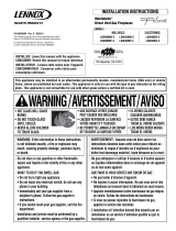
Step 2. Using a 5/16” nut driver, remove and discard the rear log sup-
port bracket per instructions in Figure 1 and using the same screws,
install the rear log support bracket provided with this kit. Orient as
shown in Figure 1.
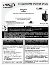
Step 3. Refer to Figure 2 and remove two screws securing the down-
draft baffle. Remove and retain the down-draft baffle.
Step 4. Remove two screws securing the restrictor base plate and
remove the restrictor assembly from the fireplace vent outlet.
Step 5. Remove two screws securing the restrictor body to the base
plate. Discard the restrictor body.
Figure 1 - Log Support Bracket
Rear Log Support
Remove the 2 screws
indicated by arrows
FIREPLACE ADAPTER KITS (For LPVK-110)
Fireplace
Model
Kit Catalog
Number Kit Contents
ELDV H7407
(ELDV-PVAK)
Table 1
5/8” Restrictor
1” Restrictor
Rear Log Bracket
VENT RUN PARAMETERS
Any Vent Run With A Vertical Height
Greater Than 30 Feet
Use 5/8” Restrictor
Provided With This Kit
Any Vent Run With A Vertical Height
Less Than 30 Feet
Use 1” Restrictor
Provided With This Kit
Note: See Power Vent Kit manual for maximum and minimum
vent run parameters.
Table 2
Figure 2 - Removing Baffle And Base Plate
NOTE: DIAGRAMS AND ILLUSTRATIONS ARE NOT TO SCALE.
Restrictor Base Plate
Restrictor Body
Down Draft Baffle

Step 6. Refer to Table 2 and determine the appropriate restrictor size
to accommodate the required vent run.
Step 7. Refer to Figure 3. If a 5/8” restrictor is required for the installa-
tion, nest the 5/8” restrictor with the 1” restrictor by aligning the mating
tabs with the mating cutouts, as shown in Figure 3. Secure the 5/8”
restrictor to the 1” restrictor by bending the mating tabs over and around
the 1” restrictor. If a 1” restrictor is called for, this assembly procedure
should not be completed.
Step 8. Position the restrictor within the fireplace vent from above
with the vent grips up, this restrictor is self centering and securing (see
Figure 4 ). If the restrictor fails to positively engage, remove it from
the vent and bend the vent grips outward and then try again.
Step 9. Replace the restrictor base plate and secure with two screws.
Replace the down draft baffle and secure with two screws. Refer to
Figure 2.
Step 10. Reinstall the glass enclosure panel per instructions in the
Care and Operation Instructions manual provided with appliance.
Step 11. Refer to the instructions (manual number 506022-01) provided
with the Power Vent Kit (LPVK-110), to complete the task of attaching
the Power Vent Kit to the ELDV Fireplace.
NOTE: DIAGRAMS AND ILLUSTRATIONS ARE NOT TO SCALE.
Printed in U.S.A. © 2008 Lennox Hearth Products
P/N 506019-26 REV. N/C 10/2008
Lennox Hearth Products
1110 West Taft Avenue • Orange, CA 92865
Lennox reserves the right to make changes at any time, without notice, in design, materials, specifications, prices and also to discontinue colors, styles and products.
Consult your local distributor for fireplace code information.
Figure 3 - Restrictor Assembly
Vent Grips
Mating Cutouts
1” Restrictor
5/8” Restrictor
Mating Tabs
Top Of Fireplace Vent Opening
Top Of Firebox
Restrictor
Assembly
6”
2”
Figure 4 - Restrictor Assembly Position
/