Page is loading ...

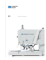
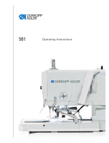
581
Operating Instructions

All rights reserved.
Property of Dürkopp Adler AG and protected by copyright. Any reuse
of these contents, including extracts, is prohibited without the prior
written approval of Dürkopp Adler AG.
Copyright © Dürkopp Adler AG 2016
IMPORTANT
READ CAREFULLY BEFORE USE
KEEP FOR FUTURE REFERENCE

Table of Contents
Operating Instructions 581 - 01.0 - 05/2016 1
1 About these instructions....................................................................5
1.1 For whom are these instructions intended? ..........................................5
1.2 Representation conventions – symbols and characters........................6
1.3 Other documents...................................................................................7
1.4 Liability ..................................................................................................8
1.4.1 Transport...............................................................................................8
2 Safety....................................................................................................9
2.1 Basic safety instructions........................................................................9
2.2 Signal words and symbols used in warnings.......................................10
3 Machine description..........................................................................15
3.1 Machine...............................................................................................15
3.2 Control panel.......................................................................................16
4 Operation ...........................................................................................19
4.1 Preparing the machine for operation...................................................19
4.2 Switching on and off the machine .......................................................20
4.3 Activating and deactivating threading mode........................................22
4.4 Inserting/changing the needle .............................................................23
4.5 Threading the needle thread...............................................................25
4.6 Threading the looper thread................................................................27
4.7 Threading the gimp thread..................................................................30
4.8 Thread tension ....................................................................................34
4.8.1 Setting the needle thread tension........................................................34
4.8.2 Setting the looper thread tension ........................................................35
4.9 Using threads and gimp threads .........................................................36
4.10 Removing and fitting clamping plates..................................................37
4.11 Swiveling the machine up and down...................................................39
4.12 Changing the blade.............................................................................41
4.13 Sewing.................................................................................................42
4.13.1 Sewing using the buttons....................................................................42
4.13.2 Sewing with the pedal .........................................................................43
5 Programming.....................................................................................47
5.1 Software description............................................................................47
5.1.1 Structure..............................................................................................49
5.1.2 Operating modes.................................................................................49
5.2 User level ............................................................................................51
5.2.1 Basic operation....................................................................................51
5.2.2 Single buttonhole mode.......................................................................51
5.2.3 Sequential mode .................................................................................52
5.2.4 Setting the cutting length.....................................................................54
5.2.5 Setting the thread tension ...................................................................55

Table of Contents
2 Operating Instructions 581 - 01.0 - 05/2016
5.2.6 Setting the cutting mode......................................................................56
5.2.7 Resetting the piece counter.................................................................57
5.3 Buttonhole programming.....................................................................58
5.4 Sequence programming......................................................................64
5.4.1 Deleting a buttonhole at the end of a sequence..................................67
5.4.2 Adding a buttonhole at the end of a sequence....................................67
5.4.3 Inserting a buttonhole within a sequence............................................68
5.4.4 Switching off sequential mode.............................................................68
5.5 Service mode ......................................................................................69
5.6 Activating the technician level.............................................................69
5.7 Buttonhole cycle..................................................................................71
5.8 Menu structure ....................................................................................72
5.9 Menu item Machine config ...........................................................75
5.9.1 Load. pos.............................................................................................75
5.9.2 Zigzag stitch width...............................................................................77
5.9.3 Thread mon.........................................................................................79
5.9.4 Cut. time..............................................................................................80
5.9.5 E-group................................................................................................81
5.9.6 Threading position...............................................................................84
5.9.7 Operation mode...................................................................................85
5.9.8 Tension data........................................................................................86
5.9.9 Multiflex (581-321 and 581-341 only)..................................................88
5.9.10 ZZ offset..............................................................................................90
5.9.11 Cut control...........................................................................................91
5.9.12 Spec.funct. ..........................................................................................91
5.10 Menu item User config. ................................................................92
5.10.1 Language ............................................................................................92
5.10.2 Buttons................................................................................................94
5.10.3 Sew.lamp.............................................................................................96
5.10.4 Key tones ............................................................................................97
5.11 Menu item Test functions ...........................................................98
5.11.1 Multitest...............................................................................................98
5.11.2 Sewing proc.......................................................................................106
5.11.3 Events ...............................................................................................113
5.12 Menu item Data transfer ............................................................116
5.12.1 Import ................................................................................................116
5.12.2 Export................................................................................................117
5.13 Menu item Reset data ..................................................................119
6 Maintenance.....................................................................................121
6.1 Cleaning ............................................................................................123
6.2 Lubricating.........................................................................................124
6.3 Servicing the pneumatic system........................................................127
6.3.1 Setting the operating pressure..........................................................127
6.3.2 Draining the water condensation.......................................................127

Table of Contents
Operating Instructions 581 - 01.0 - 05/2016 3
6.3.3 Cleaning the filter element.................................................................129
6.4 Changing the cutting blocks and blade .............................................130
6.4.1 Subclass without multiflex .................................................................130
6.4.2 Subclass with Multiflex......................................................................132
6.5 Parts list.............................................................................................134
7 Setup ................................................................................................135
7.1 Checking the scope of delivery .........................................................135
7.2 Removing the transport locks............................................................135
7.3 Assembling the stand........................................................................137
7.4 Assembling the tabletop....................................................................137
7.5 Using the ring bolt .............................................................................138
7.6 Assembling the reel stand.................................................................139
7.7 Securing the stand ............................................................................140
7.8 Setting the working height.................................................................141
7.9 Assembling the control......................................................................142
7.10 Electrical connection .........................................................................144
7.11 Establishing equipotential bonding....................................................144
7.12 Assembling the suction container......................................................145
7.13 Pneumatic connection.......................................................................146
7.13.1 Assembling the compressed air maintenance unit............................147
7.13.2 Setting the operating pressure..........................................................148
7.14 Checking the lubrication....................................................................148
7.15 Adjusting the material edge stops .....................................................153
7.16 Carrying out a test run.......................................................................154
8 Decommissioning ...........................................................................155
9 Disposal ...........................................................................................157
10 Troubleshooting..............................................................................159
10.1 Customer Service..............................................................................159
10.2 Messages of the software .................................................................159
10.2.1 Information messages.......................................................................159
10.2.2 Error messages.................................................................................162
10.3 Errors in sewing process...................................................................171
11 Technical data .................................................................................175
12 Glossary...........................................................................................181
13 Appendix..........................................................................................185

Table of Contents
4 Operating Instructions 581 - 01.0 - 05/2016

About these instructions
Operating Instructions 581 - 01.0 - 05/2016 5
1 About these instructions
These instructions have been prepared with utmost care.
They contain information and notes intended to ensure long-term
and reliable operation.
Should you notice any discrepancies or if you have improvement
requests, then we would be glad to receive your feedback through
Customer Service ( p. 159).
Consider the instructions part of the product and store them in a
place where they are readily available.
1.1 For whom are these instructions intended?
These instructions are intended for:
• Operators:
This group is familiar with the machine and has access to
the instructions. Specifically, chapter Operation ( p. 19)
is important for the operators.
• Specialists:
This group has the appropriate technical training for
performing maintenance or repairing malfunctions.
Specifically, the chapter Setup ( p. 135) is important
for specialists.
Service Instructions are supplied separately.
With regard to minimum qualification and other requirements to be
met by personnel, please also follow the chapter Safety ( p. 9).

About these instructions
Operating Instructions 581 - 01.0 - 05/20166
1.2 Representation conventions – symbols and
characters
Various information in these instructions is represented or high-
lighted by the following characters in order to facilitate easy and
quick understanding:
Proper setting
Specifies proper setting.
Disturbances
Specifies the disturbances that can occur from an incorrect setting.
Cover
Specifies which covers must be removed in order to access the
components to be set.
Steps to be performed when operating the machine (sewing
and equipping)
Steps to be performed for service, maintenance, and
installation
Steps to be performed via the software control panel
The individual steps are numbered:
1. First step
2. Second step
The steps must always be followed in the specified order.
Lists are marked by bullet points.
Result of performing an operation
Change on the machine or on the display/control panel.
Important
Special attention must be paid to this point when performing a step.
1.
2.
...
•

About these instructions
Operating Instructions 581 - 01.0 - 05/2016 7
Information
Additional information, e.g. on alternative operating options.
Order
Specifies the work to be performed before or after a setting.
References
Reference to another section in these instructions.
Safety Important warnings for the user of the machine are specifically
marked. Since safety is of particular importance, hazard symbols,
levels of danger and their signal words are described separately
in the chapter Safety ( p. 9).
Location
information If no other clear location information is used in a figure, indications
of right or left are always from the user's point of view.
1.3 Other documents
The machine includes components from other manufacturers.
Each manufacturer has performed a hazard assessment for these
purchased parts and confirmed their design compliance with ap-
plicable European and national regulations. The proper use of the
built-in components is described in the corresponding manufac-
turer's instructions.

About these instructions
Operating Instructions 581 - 01.0 - 05/20168
1.4 Liability
All information and notes in these instructions have been compiled
in accordance with the latest technology and the applicable stan-
dards and regulations.
The manufacturer cannot be held liable for damages resulting
from:
• Breakage and damage during transport
• Failure to observe these instructions
• Improper use
• Unauthorized modifications to the machine
• Use of untrained personnel
• Use of unapproved parts
1.4.1 Transport
Dürkopp Adler cannot be held liable for breakage and transport
damages. Inspect the delivery immediately upon receiving it.
Report any damage to the last transport manager. This also
applies if the packaging is not damaged.
Leave machines, equipment and packaging material in the con-
dition in which they were found when the damage was discovered.
This will ensure any claims against the transport company.
Report all other complaints to Dürkopp Adler immediately after
receiving the product.

Safety
Operating Instructions 581 - 01.0 - 05/2016 9
2 Safety
This chapter contains basic information for your safety. Read the
instructions carefully before setting up or operating the machine.
Make sure to follow the information included in the safety instruc-
tions. Failure to do so can result in serious injury and property
damage.
2.1 Basic safety instructions
The machine may only be used as described in these instructions.
The instructions should be available at the machine's location at
all times.
Work on live components and equipment is prohibited.
Exceptions are defined in the DIN VDE 0105.
For the following work, switch off the machine at the main switch
or disconnect the power plug:
• Replacing the needle or other sewing tools
• Leaving the workstation
• Performing maintenance work and repairs
• Threading
Missing or faulty parts could impair safety and damage the ma-
chine. Only use original parts from the manufacturer.
Transport Use a lifting carriage or forklift to transport the machine. Raise the
machine max. 20 mm and secure it to prevent it from slipping off.
Setup The connecting cable must have a power plug approved in the
relevant country. The power plug may only be assembled to the
power cable by qualified specialists.
Obligations
of the operator Follow the country-specific safety and accident prevention regu-
lations and the legal regulations concerning industrial safety and
the protection of the environment.

Safety
10 Operating Instructions 581 - 01.0 - 05/2016
All the warnings and safety signs on the machine must always be
in legible condition. Do not remove!
Missing or damaged warnings and safety signs must be replaced
immediately.
Requirements
to be met by
the personnel
Only qualified specialists may:
• set up the machine
• perform maintenance work and repairs
• perform work on electrical equipment
Only authorized persons may work on the machine and must first
have understood these instructions.
Operation Check the machine during operating for any externally visible
damage. Stop working if you notice any changes to the machine.
Report any changes to your supervisor. Do not use a damaged
machine any further.
Safety
equipment Safety equipment should not be removed or deactivated. If it is
essential to remove or deactivate safety equipment for a repair
operation, it must be assembled and put back into operation
immediately afterward.
2.2 Signal words and symbols used in warnings
Warnings in the text are distinguished by color bars. The color
scheme based on the severity of the danger. Signal words indicate
the severity of the danger.
Signal words Signal words and the hazard they describe:
Signal word Meaning
DANGER (with hazard symbol)
If ignored, fatal or serious injury will result
WARNING (with hazard symbol)
If ignored, fatal or serious injury can result

Safety
Operating Instructions 581 - 01.0 - 05/2016 11
Symbols The following symbols indicate the type of danger to personnel:
CAUTION (with hazard symbol)
If ignored, moderate or minor injury can result
CAUTION (with hazard symbol)
If ignored, environmental damage can result
NOTICE (without hazard symbol)
If ignored, property damage can result
Symbol Type of danger
General
Electric shock
Puncture
Crushing
Environmental damage

Safety
12 Operating Instructions 581 - 01.0 - 05/2016
Examples Examples of the layout of warnings in the text:
This is what a warning looks like for a hazard that will result
in serious injury or even death if ignored.
This is what a warning looks like for a hazard that could
result in serious or even fatal injury if ignored.
This is what a warning looks like for a hazard that could
result in moderate or minor injury if the warning is ignored.
DANGER
Type and source of danger!
Consequences of non-compliance.
Measures for avoiding the danger.
WARNING
Type and source of danger!
Consequences of non-compliance.
Measures for avoiding the danger.
CAUTION
Type and source of danger!
Consequences of non-compliance.
Measures for avoiding the danger.

Safety
Operating Instructions 581 - 01.0 - 05/2016 13
This is what a warning looks like for a hazard that could
result in property damage if ignored.
This is what a warning looks like for a hazard that could
result in environmental damage if ignored.
NOTICE
Type and source of danger!
Consequences of non-compliance.
Measures for avoiding the danger.
CAUTION
Type and source of danger!
Consequences of non-compliance.
Measures for avoiding the danger.

Safety
14 Operating Instructions 581 - 01.0 - 05/2016

Machine description
Operating Instructions 581 - 01.0 - 05/2016 15
3 Machine description
3.1 Machine
Fig. 1: Machine Description (1)
(1) - Button for threading mode
(2) - Buttons (3) - Control panel
③
①
②

Machine description
Operating Instructions 581 - 01.0 - 05/201616
The machine is fitted with a programmable control and a control
panel.
These can define up to 50 different buttonholes.
The buttonholes can be programmed in up to 25 sequences
( p. 47).
A sequence can include a maximum of 9 different buttonholes;
each individual buttonhole within the sequence can be repeated
up to maximum 9 times consecutively.
During sewing, it is possible to switch automatically or manually
between the programmed buttonholes ( p. 58).
3.2 Control panel
The OP5000 control panel is located on the side of the machine
and is connected to the control. Using the control panel, you can
set the functions for the relevant buttonhole.
The control panel comprises:
• Display
• Buttons

Machine description
Operating Instructions 581 - 01.0 - 05/2016 17
Fig. 2: Machine Description (2)
Buttons and functions of the control panel
(1) - P Button
(2) - ESC button
(3) - Arrow button
(4) - Arrow button
(5) - OK button
(6) - Arrow button
(7) - Arrow button
(8) - F button
(9) - S button
No. Button Function
①• Calls up the setting mode for individual
buttonholes
②• Returns to the user level
• Rejects changes
③• Moves one level down
• Changes to previous buttonhole shape
④• Moves to the menu item one field lower
• Reduces values
⑤• Calls up values
• Saves changed values
①
②
③
④ ⑤
⑧
⑦
⑥
⑨

Machine description
Operating Instructions 581 - 01.0 - 05/201618
⑥• Changes to the next buttonhole shape
⑦• Moves to the menu item one field higher
• Increases values
⑧• Calls up service mode
⑨• Calls up the setting mode for buttonhole
sequences
No. Button Function
/