ZKTeco ProlD Series User manual

Type
User manual

ZKTeco ProlD Series is a water-resistant RFID access control reader that provides secure and convenient access control solutions for various applications. With its IP65-rated weatherproof design, it can withstand harsh outdoor conditions, making it suitable for both indoor and outdoor use. The reader supports multiple card formats, including ID and IC cards, and offers a read range of up to 5 cm. It features Wiegand 26-bit or 34-bit (adjustable) and RS485 output formats for easy integration with existing access control systems.

ZKTeco ProlD Series is a water-resistant RFID access control reader that provides secure and convenient access control solutions for various applications. With its IP65-rated weatherproof design, it can withstand harsh outdoor conditions, making it suitable for both indoor and outdoor use. The reader supports multiple card formats, including ID and IC cards, and offers a read range of up to 5 cm. It features Wiegand 26-bit or 34-bit (adjustable) and RS485 output formats for easy integration with existing access control systems.

QUICK START GUIDE
Applicable Model: ProlD Series
Version: 1.1
Date: March 2023
Water Resistant RFID Access Control Reader
1.Product Overview
ProID
ProID
0.5" (11.6mm) 3.4"(86.0mm)
3.4"(86.0mm)
LED
Indicator
DIP
Switch
Mounting
Hole
LED
Indicator
Mounting
Hole
0.4" (11.0mm) 1.8"(44.5mm)
4.4"(111.0mm)
1
DIP
Switch
Buzzer
Buzzer
Back Plate
2
3.1"(80.0mm)
3.2"(80.3mm)
0.5" (13.0mm)
2.4"(60.0mm)
ProID
3.0"(76.0mm)
4.8"(123.0mm)
LED
Indicator
Buzzer
0.5" (11.6mm)
DIP
Switch
Mounting
Hole
ProID101 ProID102
1.4"(36.0mm)
4.3"(109.7mm)
0.5" (12.8mm)
Tamper
Switch Tamper
Switch
Power
Wiegand 26/34
Beep
Red LED
Green LED
Tamper
RS-485
+12V
GND
RS485A
RS485B
WD0
WD1
WG26/34
BEEPER
RLED
GLED
TAMPER
Wiegand Out
2.Terminal Block
4.4"(111.2mm)
2.9"(73.0mm)
0.5" (13.0mm)
2.4"(60.0mm)
ProID103
3
Tamper
Switch
Install on the wall
1 2
43




Attach the mounting template sticker to the wall, and drill holes according to
the mounting paper.
Secure the back plate on the wall with the wall mounting screws.
After passing the wires through the wiring hole and connecting them to the
device, and then attach the device to the back plate from top to bottom.
Fasten the device to the back plate with a security screw.
Note: The installation method of ProlD103 is the same as that of ProlD102.
Only ProlD102 is used as an example, and will not be repeated here again.
4
1
2
1.5m
Baseline
3.Device Installation
5
Mounting on the wall through Asian gang box
1
2
3
5
Install the box (or Asian gang single gang box, mullion mount) into the wall.
Fix the back plate onto the Asian gang box (or single gang box, mullion mount)
using two wall mounting screws.
Pass the cables through the wire hole.
Then insert the device into back plate.
Use security screw to fasten the device to the back plate.
The installation method of single gang box is the same as that of Asian Note:
gang box. Only Asian gang box installation method is illustrated as an example
in this quick start guide.




Asian gang box
4

6
As shown in the table below, places 1-3 of the DIP switch are used to set the
device number for RS-485 communication, and place 4 is for setting the RS485
termination resistance. If the RS-485 communication wire is longer than 100
meters, it is needed to set the 4th DIP switch of the last reader to ON state, that is
parallel a terminal resistance of 120 ohm between 485+ and 485-.
485 Address Switch Setting Switch Setting
1
2
3
4
ON KE
12 3 4
ON KE
12 3 4
ON KE
12 3 4
ON KE
12 3 4
485 Address
ON KE
1234
ON KE
1234
ON KE
1234
ON KE
1234
5
6
7
Terminal
Resistance
ON KE
12 3 4
12 4
Terminal
Resistance
DIP Switch
TCPIP
TCPIP
Electric Lock
Door Sensor
InBio Series Controller
ProlD102 ProlD103
Wiegand
STATE
PWR
EXT
RS485
PC
RS485
SWITCH
RS485
PC
4.DIP Switch Settings
5.Standalone Installation
ProlD101
This ProlD series reader needs to be connected to a host machine in order to
transmit card information via RS-485 or wiegand. The following is an example
of the connection to InBio Series controller.
Connect the controller via RS485
#2
TCP/IP
PC
STATE
PWR
EXT
RS485
PC
RS485
SWITCH
Router #1 #6
DC12V DC12V
#7
RS-485A
RS-485B
GND
+12V
ON KE
12 3 4
ON KE
12 3 4
ON KE
12 3 4
ON KE
12 3 4
Notes:
7
1. A maximum of seven readers can be connected to one controller.
2. Before connecting RS-485 readers, open the rear panel of the reader and set
the RS-485 address of the reader via DIP switch according to the connection
of each reader.
3. If the RS-485 communication wire is longer than 100 meters, it is needed to
set the 4th DIP switch of the last reader to ON state.
4. The DIP switch needs to be set with the controller powered off and takes
effect after restart. After setting, the DIP switch does not need to be set
back to its original position.
6.Controller Connection
Connect the controller via Wiegand
TCP/IP
PC
Router
STATE
PWR
EXT
RS485
PC
RS485
SWITCH
BEEP
GLED
WD1
WD0
GND
+12V
READER1
InBio Series
Conttroller
DC12V
BEEPER
GLED
WD1
WD0
GND
+12V
WG26/34
Note:
+12V
GND
RS485A
RS485B
WD0
WD1
WG26/34
BEEPER
RLED
GLED
TAMPER
+12V
GND
RS485A
RS485B
Access Control Device
8
ON KE
12 3 4
ProlD Series Reader
When terminal WG26/34 is connected to
ground, the number of Wiegand output
bits is 26 bits. The default is not grounded,
and the number of Wiegand output bits is
34 bits.
7.Access Control Device Connection
12V
GND
D0
D1
RLED
GLED
BUZ
TMPR
When the tamper switch terminal is successfully connected to the controller,
the device will sound an alarm when the back plate of the device is opened,
and an alarm signal will be sent to the software side.
+12V
GND
RS485A
RS485B
WD0
WD1
WG26/34
BEEPER
RLED
GLED
TAMPER
ON KE
12 3 4
Controller
Recommended : 7 to 13V DC, Current Draw > 350mA/5V.AC adapter
Use an AC adapter with a higher current rating to share power with the
other devices.
AC Adapter
7-13V DC
9
8.Tamper Switch Connection
9.Power Connection
10
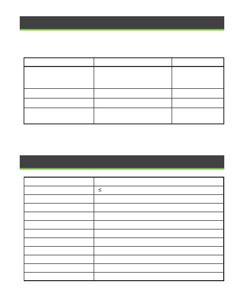
When the ProlD series reader works normally, the buzzer and indicator prompts
are shown in the following table.
Working Status
1 short sound
1 short sound
Buzzer
When the reader is
powered on.
1 short sound
2 short soundCard not registered
Card is registered
When punching the card.
Indicator Light
LED bright white light,
then switch to white light
breathing state after 0.4s.
LED indicator lights green.
LED indicator (red) lights up
briefly twice.
LED bright white light.
Operation Voltage
Current Draw
Processor
Card Type
Read Range
Output Format
Operating Temperature
Operating Humidity
Protection Rating
Installation
Color
Certfication
7 to 13V DC
350mA 5V
32-bit ARM Cortex-M0 48MHz
ID/IC Card
0 to 5 cm
Wiegand 26bit or 34bit (Adjustable), RS485
-20 °C to 65 °C
10% to 90% RH, Non-Condensing
IP65, IK04
Asian gang box, single gang box, mullion mount
Black & White
ISO9001, ISO14001, CE, FCC
10.Buzzer, Indicator Light Prompt Instructions
11.Specif ications
Note: In Wiegand communication mode, the status of LED and buzzer is controlled
by the host when the card is swiped.
ZKTeco Industrial Park, No. 32, Industrial Road,
Tangxia Town, Dongguan, China.
Phone : +86 769 - 82109991
Fax : +86 755 - 89602394
www.zkteco.com
Copyright © 2023 ZKTECO CO., LTD. All Rights Reserved.
  • Page 1 1
  • Page 2 2
  • Page 3 3
  • Page 4 4
  • Page 5 5
  • Page 6 6
  • Page 7 7
  • Page 8 8
  • Page 9 9
  • Page 10 10
  • Page 11 11
  • Page 12 12

ZKTeco ProlD Series User manual

Type
User manual

ZKTeco ProlD Series is a water-resistant RFID access control reader that provides secure and convenient access control solutions for various applications. With its IP65-rated weatherproof design, it can withstand harsh outdoor conditions, making it suitable for both indoor and outdoor use. The reader supports multiple card formats, including ID and IC cards, and offers a read range of up to 5 cm. It features Wiegand 26-bit or 34-bit (adjustable) and RS485 output formats for easy integration with existing access control systems.

Ask a question and I''ll find the answer in the document

Finding information in a document is now easier with AI