U
U
t
t
i
i
l
l
i
i
t
t
y
y
V
V
e
e
h
h
i
i
c
c
l
l
e
e
O
O
p
p
e
e
r
r
a
a
t
t
o
o
r
r
s
s
M
M
a
a
n
n
u
u
a
a
l
l
Copyright
January 12, 2010

2
INDEX
Section 1 Introduction pages 3-4
Serial Number Plate Location
Section 2 Safety pages 5-10
Pre-Delivery Steps
Dealer Inspection Checklist
Section 3 Assembly Instructions pages 11-13
Seat Back, Brush guard, Bumper
Steering wheel
Cargo Bed
Seat Base
Section 4 Operating Instructions page 14 – 29
390cc 4X4
653cc 4X4
48 Volt Electric
Section 5 Maintenance pages 30-33
Fuel Valve Lever
Air Cleaner
Engine Oil / Transaxle Oil
Drive Belt
Section 6 Troubleshooting pages 34-40
Section 7 Parts Diagrams pages 41-112
Wiring Diagram
2WD Dana Transaxle
265cc 2 wheel drive
340cc 2 wheel drive
4WD Dana / Hilliard Transaxle
390cc 4-wheel drive
653cc 4-wheel drive
48 Volt 2-Wheel Drive
Warranty Policy page 113
Contact Information page 114
Warranty Registration Certificate page 115

3
Section 1 Introduction
American SportWorks welcomes you to its growing
family of new product owners. This Utility Vehicle
“UTV” is a light utility vehicle that has been designed
with care and built by skilled workers using quality
materials. Proper set-up, maintenance and safe
operating practices will help you get years of
satisfactory use from this vehicle.
Safety First
American SportWorks is fully aware of the need for safe
operating procedures around all of our equipment. We
hope you will make a sincere effort to put safety above
all other priorities. The Utility Vehicle was designed and
built for work, recreation, and enjoyment; however,
improper and irresponsible operation could result in
serious injury or death. Since this is an off-road vehicle,
operators will seldom see the road safety and warning
signs they are accustomed to seeing on highways and
public streets. This places additional responsibility on
the driver to operate this vehicle well within the safe
operational limits and capabilities of the unit.
This manual has been prepared to instruct you in the
safe and responsible operation of your Utility Vehicle.
Read and abide by all safety alert information about this
vehicle. If you do not understand any part of this
manual, contact your local dealer for additional
information and clarification. As the operator of this
piece of equipment, you are in complete control. Only
you can prevent an accident from happening.
Using This Manual
* Prior to any vehicle operation it is absolutely essential
that you read and comprehend each section in this
manual to develop an understanding of your vehicle and
for your safety. After reviewing this manual, store it in a
dry and easily accessible place for future reference.
* The Operator’s Section is designed to help familiarize
you with safety, assembly, operation, adjustments,
troubleshooting, and maintenance. Read this manual
and follow the recommendations to help ensure safe
and efficient operation.
* The information contained within this manual was
current at the time of printing. Some parts may change
slightly to assure you of the best performance.
* To order a new Operator’s or Parts Manual contact
your authorized dealer.
American SportWorks LLC
Toll Free PH: 1-866-646-5278
Fax: 1-866-329-5278
www.amsportworks.com
Terminology
Right-hand and left-hand as used in this manual are
determined by facing the direction the vehicle will travel
while in use unless otherwise stated.
Getting Acquainted with your Utility Vehicle
This off-road utility vehicle is a very unique vehicle
designed exclusively for off-road use. It is not designed,
properly equipped, or licensed to be safely operated on
public streets and highways. This vehicle is designed to
carry two people and a limited amount of gear or cargo
comfortably and safely over rough terrain that was only
accessible by ATV’s in the past.
Unlike ATV’s that have handlebar steering, Utility
Vehicle’s have a steering wheel with easy handling
rack-and pinion steering. The steering’s tight turning
radius makes this vehicle more maneuverable than
most ATV’s. Its four wheeled independent suspension,
large diameter hi-flotation tires and high center-frame
ground clearance adds up to excellent stability and a
smooth ride over rough terrain. Outstanding two
wheeled rear traction drive is achieved by using
premium off-road ATV type tires in tandem with the
engine mounted directly in front of the rear differential.
Also unlike an ATV’s one person “straddle saddle” seat,
the Utility Vehicle sports dual headrest cushioned seats
with seat belts mounted in a highly styled and protective
full length body. Two passengers can ride comfortably in
this vehicle protected from splashing water and mud.
The Brush Guard Bar mounted to the vehicle’s frame
provides protection against low hanging limbs and
briars.

4
Section 1 Introduction
The Brush Guard Bar also provides a mounting system
for American SportWorks optional windshields, canopy
tops and weather enclosures. It also serves as a
mounting base for many other optional cargo racks, gun
and bow racks.
The cargo bed is for transporting accessories such as
camping equipment, tree stands, hunting gear, and
fishing gear. A standard hitch mounting plate enables
quick installation of a rear hitch for pulling small trailers
full of supplies, tools, gear, and game.
The Utility Vehicle has some similarities to an ATV. Like
an ATV the Utility Vehicle has a short wheelbase,
narrow stance, and high center clearance all which
provide for narrow and difficult trail access. This
combination of short wheelbase and narrow stance also
enables this vehicle to be loaded in the back of most full
to mid-sized pickups for transport.
The Utility Vehicle’s ground compaction and is very
gentle on the ground and surrounding vegetation. The
highly energized four wheeled independent suspension
system provides an incredibly soft ride and outstanding
stability over difficult terrain. The engine is EPA certified
and meets California Air Resources Board (CARB)
certification standards.
Owner Assistance
The safety information should be viewed by the owner
and the Warranty Registration card should be filled out
by the dealer at the time of purchase. The owner, upon
purchasing the vehicle, should have participated in a
short drivers training course with the dealer. This
information is necessary to provide you with quality
customer service.
The parts on your Utility Vehicle have been specially
designed and should only be replaced with genuine
American SportWorks parts.
If customer service or repair parts are required contact a
American SportWorks dealer. They have trained
personnel, genuine repair parts and equipment specially
designed to repair American SportWorks products.
American SportWorks LLC
4404 Engle Ridge Drive
Fort Wayne, IN 46804
Toll Free PH: 1-800-643-7332
Fax: 1-800-399-1399
service@amsportworks.com
Always use the serial and model number when ordering
parts for your Utility Vehicle. The serial-number plate is
located under the cargo bed on the driver’s side just
above the engine, on the frame as shown in figure 1
below.
Serial Number Plate Location
Figure 1
Record your Utility Vehicle serial number here for quick
reference:
Model Number:___________________________
Serial Number:____________________________
Your American SportWorks dealer wants you to be
satisfied with your new vehicle. If you do not understand
any part of this manual or you’re not satisfied with the
service received, please take the following actions.
Discuss the matter with your dealership service
manager. Make sure they are aware of any problems so
they can assist you.
If you are still unsatisfied, seek out the owner or general
manager of the dealership.
For further assistance write to

5
Read These Important Rules
for Safe Operation
Note: The Operator, Passenger, Parent or Guardian must read, study and understand all the items contained
within this owners/operators manual before operating utility vehicle. Failure to follow these instructions
could endanger the personal safety of the Operator, Passenger and any Bystanders.
Close adult supervision is required at all times!
Pay close attention to all Caution and Warning labels
Located on the Utility Vehicle
*IMPORTANT*
When transporting any Utility Vehicle with an installed windshield or
Color matched top DO NOT reach high speeds!
Assumption Of Risk
The owner or operator assumes all the risks incident to or arising out of the operation of
this Utility Vehicle
Failure to follow and comply with all warnings may
cause serious injury or death

6
Section 2 Safety
It is very important to read, understand, and follow all
instructions and warnings located on the decals on your
Utility Vehicle.
Rear Seat
Weight Limit is 300lbs

7
Section 2 Safety
Safe Operating Procedures
The safe operation of any machinery is a big concern to
all consumers. Your Utility Vehicle has been designed
with many built-in safety features. However, no one
should operate this vehicle before carefully reading this
Operator’s Manual. Also read all instructions noted on
the safety decals.
* Be familiar with all functions of this vehicle.
*
Keep all bystanders away from this vehicle during
operation.
* Do not allow anyone to operate this vehicle who has
not fully read and comprehended this manual and who
has not been properly trained in the safe operation of
this vehicle.
* Do not operate a vehicle with damaged or defective
parts. Repair all damages and defective parts before
putting vehicle back in to service.
* Do not allow anyone under 16 years of age to operate
this vehicle.
* Operator must always use both hands on the steering
wheel.
* No riders allowed except in factory designed and
supplied seating.
* Operate this vehicle from the driver’s seat only.
* Do not leave this vehicle unattended with engine
running.
* Do not dismount a moving vehicle as serious injury or
death could occur.
* Always operate vehicle with belt guard installed. Do
not leave pulleys and belts exposed.
* Do not touch engine, engine exhaust pipe and/or
muffler while they are hot.
* Keep hands, feet, long hair, clothing, and jewelry away
from moving parts and obvious pinch points to avoid
getting caught.
* Wear snug-fitting clothing to avoid entanglement with
moving parts.
* Some conditions may warrant extra safety gear to be
worn such as safety helmets and/or goggles.
* Keep hands, arms, feet and all bodily appendages
safely inside the confines of the vehicle.
* Always be aware of and avoid tree limbs and brush
that have a potential of hitting and/or poking individuals
riding the vehicle. Serious body harm could result.
* Avoid sudden stops, starts, and turns.
* Always operate your vehicle at a safe speed that will
allow you to maintain control.
* Operator and passenger are responsible for deciding if
their situation warrants using seat belts.
* Do not exceed total payload capacity of this vehicle.
* Do not pull a trailer or implement exceeding 1100
pound towing capacity or loss of control may result.
* Do not attach an implement, trailer or other device to
the hitch that will produce negative tongue weight.
* Follow all towing instructions in this manual when
towing the UTV behind another vehicle. Do not tow
vehicle faster than 25 MPH.
* Do not use the vehicle as an anchor device.
* Beware, tow ropes, cables and chains can break when
pulling another vehicle or object causing serious injury
or death to anyone in line with the whipping action
created when they break. Never jerk when pulling,
always ease into a pull gently. Always stay clear of the
tow line. Never be in line with the tow line.
* Reduce speed when loaded with cargo. Heavy cargo
load takes longer to stop.
* Reduce speed and payload on hilly, rough, wet, slick
or unstable ground.
* Always make turns at a speed that will maintain control
of vehicle. Never make turns at full speed. Reduce
speed when turning empty and reduce speed even
more when turning loaded with cargo or when pulling a
cargo load. The heaver the cargo load, the slower the
turn should be.
* Make sure all gear or cargo is properly secured and
tied down.

8
* Do not exceed 400 lbs. in cargo bed area (NOTE:
300lbs with rear seat kit installed), or 900 lbs. total on
this vehicle.
* Do not mount a receiver hitch type carrier platform to
the vehicle.
* Do not load the Brush Guard Bar with heavy
equipment. Rollover could result from such loading.
* The Brush Guard Bar is not certified ROPS (Roll Over
Protection System). Always avoid rollovers.
* Do not operate this vehicle on highways, public roads,
or where it may be a hazard to faster moving traffic.
* Do not operate this vehicle while drinking or under the
influence of alcohol and drugs.
* Never attempt wheelies, jumps, or other stunts. Never
drive recklessly. Always operate your vehicle at a safe
speed that will allow you to maintain control.
* Never use vehicle for racing and never modify the
engine to exceed 25 MPH vehicle speed.
* Never modify any parts on the vehicle without
authorization. Unauthorized modifications will void
warranty to all parts directly and indirectly affected by
the modification.
* Always make sure the vehicle pathway is clear of all
objects when backing up. Know location of personnel
around vehicle and especially location of small children.
Take extra precautions when rear view is hindered by
cargo.
* Always park on level ground, stop engine, set parking
brake and remove ignition key before leaving the
vehicle. Chock tires if condition warrants.
* Use extreme caution when cresting hills or when
visibility is limited. Proceed slowly until you are sure trail
conditions immediately ahead are safe.
* Keep front wheels straight when cresting hills or going
over bumps.
* Do not stop, start suddenly or over accelerate on hills.
Loss of control and rollover could result.
* Use extreme caution when descending hills or running
on loose slippery surfaces. Towing, braking, and tractive
capabilities are greatly diminished.
* Do not operate vehicle on 15 degree slopes or
steeper.
* Avoid changing direction or making sharp steering
corrections on slopes or rollover may occur.
* If this vehicle begins to tip when crossing a slope, turn
the front wheels downhill to regain stability and control.
* When crossing a slope on soft terrain, turn the front
wheels slightly uphill and maintain a constant speed to
maintain a straight line of travel.
* When descending hills or slopes apply steady
pressure to the foot brake to avoid potential of
freewheeling or runaway.
* Never allow vehicle to coast or free wheel in neutral or
loss of control may result.
* If your vehicle loses power and stops on a hill,
immediately engage the foot brake and back slowly
down the hill maintaining a straight downhill line of
travel. Do not attempt to turn the vehicle sideways on
the hill or a rollover could result.
* When traveling at night always use your headlights
and reduce speed according to visibility, trail, and terrain
conditions.
* Avoid water crossings when possible and never cross
a body of water where depth is unknown. Loss of power
will occur if the drive belt becomes submerged or wet.
Unnecessary crossing of streams and waterways
erodes shore line and damages water-born habitat. If
you must cross, do it at a point where banks are not
steep and proceed at a slow and steady speed.
* Front bumper and brush guards are not designed as
pusher bars. Do not attempt to push other vehicles or
implements or damage may result.
* When refueling use an (UL) approved non-metallic
container that has no screen or filter. Set the container
on the ground before fueling to eliminate static
discharge and do not use Methanol fuel.
* Do not smoke or use electrical devices including cell
phones while refueling.
* Always maintain proper tire inflation.
* Always disconnect the negative battery terminal before
making adjustments to the vehicle electrical system or
welding on this vehicle.
* Battery fumes are explosive. A spark will ignite battery
fumes. Wear a face shield when charging or jumping a

9
battery. Follow all battery safety rules outlined in this
manual.
* Avoid battery acid spills. Do not get battery acid on
eyes, face, or other body parts. Flush eyes and other
body parts immediately with water for at least 15
minutes if battery acid has gotten on them.
* Always check wheel lug nut torque values two hours
after initial operation and two hours after each tire repair
and/or replacement. Routinely check lug nut torque
valves every 100 hours of operation.
* Support this vehicle securely before working beneath.
Chock the wheels to prevent the vehicle from rolling.
* Do not shift transaxle unless this vehicle is fully
stopped and the engine is at idle or damage may occur.
Each vehicle must undergo a Pre-Delivery Inspection
by the Dealer. Listed below is an example of the
checklist that is included with the Warranty Registration
that is to be submitted to American SportWorks upon
Retail Sale. The Pre-Delivery Certificate and Warranty
Registration must be submitted to American SportWorks
in order to activate the vehicle warranty.
Pre-Delivery Steps
The dealer is required to complete “Pre-Delivery” steps
before customer may take possession of the vehicle.
This information must be filled in and check list checked
off or initialed by individuals performing the checks.
Dealership’s name, signatures of individuals filling in the
form, seller’s signature, customer’s signature, and
signing dates are also required.
Below is a list of the information that is required
to be completed and checked off.
Vehicle Information
Model No. ___________
Date ___________
Serial No. ___________
Engine Serial No.
Dealer Service and Inspection List
__ Fully charge battery. Check battery voltage to verify
that it is fully charged.
__ Check fuel valve lever to make sure it is in the
correct position.
__ Check tire pressure to make sure front and rear tires
have 5 psi.
__ Make sure wheel lug bolts/nuts are tightened to 90
Newton meters (65ft.lbs).
__ Check engine oil level at the dipstick. Add SAE
10W30 oil if oil is below the full mark on the dipstick.
*this should be done with seat (and under seat storage
Tray if equipped) removed, with UTV on flat level
surface
__ Check engine for correct RPM. Set to factory
specification if needed.
__ Check tie rods for tightness.
__ Check Choke Control. It should move and return
freely.
__ Step on foot brake to make sure the pedal is firm and
does not go to the floor.
__ Make sure seats and seat belts are properly fastened
to the frame.
__ Make sure all safety decals are in place.
__ Check headlights to make sure they are working and
are properly mounted.
__ Inspect air cleaner element. Make certain it is clean
and in place.
__ Inspect the fuel tank to make sure it is properly
installed and that there are no leaks.
__ Check fuel level to make sure there is at least 1/8 of
a tank of gas prior to performing initial starting
operations.
__ Inspect fuel lines to make sure they are properly
installed and that there are no leaks.
__ Check steering by executing a full lock to lock turn in
each direction.
__ Check parking brake to make sure it will engage,
hold and release.
__ Check throttle control to make sure it moves and
returns freely.
__ Check differential oil level at the differential oil plug.
Add 30 weight oil if oil is low.

10
__ Check overall appearance for cleanliness and for
body and molding damage.
Dealer Test Ride List
__ Check engine for starting, accelerating, running
smooth, and idling smoothly.
__ Check steering response. There should be no free
play.
__ Check forward, neutral, and reverse shifting
response. Also check neutral start response.
__ Check parking brake to make sure it engages, holds,
and disengages.
__ Make sure throttle is responsive and returns freely.
__ Make sure the suspension ride is satisfactorily and
stable.
__ Make sure there are no fuel or petroleum leaks.
__Make sure the foot brake has a firm engagement and
that stopping is straight.
__ Make sure there are no abnormal rattles or
vibrations.
Dealer Delivery to Customer List
__ Warranty registration form is complete.
__ Owner’s Manual has been delivered to and reviewed
by the customer.
__ Engine Manual has been delivered to and reviewed
by the customer.
__Warranty Policy limits and requirements have been
explained to the customer.
__ Location and functions of vehicle controls have been
explained.
__ Fuel transportation and storage procedures have
been explained.
__ Fluid fill and lubrication points have been located and
explained to the customer.
__ Information on the safety decals have been reviewed
with the customer.
Customer Acceptance List
Customer initials required where accepted as
successfully completed.
__ Customer has reviewed and understood warranty
policy (ies).
__ Customer has inspected the vehicle and it meets
customer satisfaction.
__ Customer understands the importance of following
the owner’s manual instructions.
* IMPORTANT NOTICE *
* IMPORTANT NOTICE ** IMPORTANT NOTICE *
* IMPORTANT NOTICE *
WHEN TRANSPORTING ANY
UTILITY VEHICLE WITH A WINDSHEILD OR
COLOR MATCHED TOP INSTALLED
DO NOT EXCEED 55MPH
American SportWorks LLC
Toll Free PH: 1-866-646-5278
Fax: 1-866-329-5278
www.amsportworks.com
__ Transportation of utility vehicle is limited to 55mph,
when equipped with top and windshield

11
Section 3 Assembly Instructions
Utility Vehicle
Assembly Instructions
Your new Utility Vehicle Utility vehicle should include the following items to be assembled:
Qty
Item
1 #8 black screw (steering cap)
3 ¼” x 1 ¾” Hex head bolts
7 ¼” nylock nuts
4 ¼” x ¾” carriage bolts
4 ¼” flat washers
8 5/16” x 2” socket head bolts
12 5/16” curved washers
10 5/16” nylock nuts
4 5/16” x 2” hex head bolts
2 5/16” center lock nuts
Qty
Item
2 5/8” x 4” Hex bolt
2 5/8” nylock nuts
1 set of keys
1 Steering wheel (with cap)
1 Bumper
2 Rear fenders
2 Rear frame stubs
1 Seat back
1 Cage
1 Cargo Bed with tailgate

12
Section 3 Assembly Instructions
Pre-Assembly Instructions
1) Read Owner’s Manual.
2) Unpack all vehicle and assembly parts. Make sure you
have everything listed on the previous page.
3) If you have any questions or problems with your
American SportWorks LLC product please call us,
toll free 1-866-646-5278.
Seat / Brushguard Assembly
1) Place seat back frame on vehicle frame tubes.
Insert a 5/16” x 2” socket head bolt through
both bottom joints. The head of the bolt should
be on the outside of the vehicle. Put a curved
washer on the threaded end of the bolt. Place
a 5/16” nylock nut on the bolts but do not
tighten.
2) Place the cage on front vehicle frame tubes
and seat back. Insert a 5/16” x 2” socket head
bolt through all four joints. The head of the
bolt should be on the outside of the vehicle.
Put a curved washer on the threaded end of
the bolt. Place a 5/16” nylock nut on the bolts.
Tighten all 6 nuts (including step 3).
Bumper Installation
1) Align the holes in the front bumper with the
mounting holes in the front frame tubes. Insert
the four 5/16” x 2” bolts through the bumper
bracket and then into the frame tubes. Put a
curved washer on the threaded end of the bolt.
Place a 5/16” nylock nut on the bolts and
tighten.
Steering Wheel Installation
1) Remove the plastic steering column cover by
removing the 3 screws on the bottom with a
5/16” socket. If equipped with top and bottom
steering column covers
2) Turn vehicle steering so that it is pointed
straight forward. Line up holes in steering
wheel with mounting holes so that the center
spoke is pointing down. Install ¼” x 1 ¾” hex
head bolts from the back. Tighten with ¼”
nylock nuts.
3) Install steering cap with #8 black screw.
4) Re-install steering column cover.

13
Cargo Bed Installation
1) Locate rear frame stubs at the rear of frame.
The bed pivot tube on the stub should be at
the top. Insert 5/16” x 2” socket head bolt.
Loosely install 5/16” center lock nut (do not
tighten until after cargo bed is installed)
2) Place the cargo bed on the vehicle and insert a
5/8” x 4” hex head bolt through each pivot
bracket and frame stub tube.
3) Tighten both 5/16” frame stub bolts and nuts.
4) Install the 5/8” nylock nuts on the pivot bolts.
Tighten the pivots and then loosen ¼ turn.
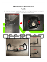
5) Loosen the bed latch pin bolt on the frame just
enough for it to slide in the adjustment slot.
(shown in upper right photo)
6) Close the bed and position the latch pin bolt so
that it is at the bottom of the latch slot to
prevent rattles. Tighten the latch pin.
7) Fenders installation (if Equipped, no fenders
on TW265) Tilt the cargo bed up. Line up the
holes in the rear fenders with the square holes
in the bed. The raised rectangular surface on
the fender should be completely hidden under
the bed. If not, turn the fender around. Insert
a ¼” x ¾” carriage bolt through the bed and
into the fender. Fasten with a ¼” flat washer
and a ¼” nylock.
Seat Base Installation
1) Place tabs attached to seat base under front seat
frame bar (if equipped into slots in plastic tray), fold
seat base into position. (if equipped The rear tabs
should fall into the slots in the rear of the plastic
tray)

14
Section 4 Operating Instructions
General Operation
Start your Utility Vehicle by following the starting
procedures as noted below.
1. Depress brake pedal with your foot and hold.
Pull firmly up on the park brake lever with your
hand until the lever is tight.
2. Place gearshift in neutral
3. Apply choke fully when engine is cold.
4. Turn ignition key fully clockwise and hold to stop
engine.
5. Release ignition key to run position and choke
to normal operating position immediately after
engine starts.
6 Turn ignition key counterclockwise to stop
engine.
Driving is as easy as driving a car with an automatic
transmission. A simple forward and reverse shifter
provides direction control.
Just turn the key and the 12 volt electric starter provides
safe and easy starting. There is a manual choke control
below the seat for quick cold weather starting. A back-up
pull-rope starter mechanism is provided on the engine
just in case you accidentally leave the key on and run
the battery down. The infinitely variable torque converter
drive system means there is no clutching. You just shift
into either forward or reverse when the vehicle is
stopped and press the throttle pedal to go. Never shift
while the vehicle is moving.
Braking is accomplished by simply depressing the brake
pedal that is located on the floorboard left of the
accelerator. A lever action parking brake control is
mounted on the center console located between the
operator and passenger seats. Depress the button on
the park brake control lever to release the park brake.
Pre-Start Check List
__
Check tire pressure as indicated.
__ Make sure wheel lug bolts/nuts are tightened to 65ft.
lbs.
__ All nuts, bolts, screws, and fasteners should be
checked.
__ Turn on headlights to make sure battery has a charge
and electrical lighting circuit is working.
__ Check tail lights and brake lights. (if applicable)
__ Check park brake to make sure it will engage, hold
and release.
__ Check steering by executing a full lock to lock turn in
each direction.
__ Check engine oil level at the dipstick. Add oil as
indicated.
__ Check differential oil level at the differential oil plug.
Add gear lube as indicated.
__ Check fuel valve lever position. Valve lever should be
off except when running the engine.
__ Check fuel level to make sure there is at least 1/8 of a
tank of gas prior to performing initial starting operations.

15
4x4 Utility Vehicles
This supplement covers the additional features,
operation and maintenance of the 4x4 Utility Vehicles
Features
• 653cc Subaru engine
• 390cc Honda engine
• Electric 4x4 selection
• Auto-Locking front differential
• Manual locking rear differential
• 4 wheel hydraulic brakes
o Front disk
o Rear drum
•
Long travel strut front suspension
Operation of Four Wheel Drive
Features
The rear axle is equipped with a manually operated
differential lock. It is engaged (locked) by moving the
differential lever to the left and down. Locking the
differential sends equal power to both rear wheels for
better traction. It may be used in both 2WD and 4WD
modes.
Note: Locking the differential on paved or hard
surfaces may increase steering effort and tire wear.
To switch to four wheel drive, the front wheels are
engaged simply by flipping the dashboard switch to
4WD. In 4WD mode power is automatically sent to the
front wheels when the rear wheels lose traction.
Warning: Bring engine to an idle before
selecting 4WD mode. Sudden engagement of
4X4 switch under power may damage drive
train. Failure to do so may void warranty.
Because the power transfer is automatic, you may
operate the vehicle in 4WD mode continuously without
affecting steering effort or tire wear.
Maintenance
Hydraulic Brakes – Hydraulic Brakes use fluid
pressure to transfer the braking force to the wheels.
Before driving the vehicle each day, check the fluid
level in the reservoir. The reservoir is located under
the hood behind the front differential gear box. Fill to
the MAX line with DOT 3 brake fluid.
If you notice that the brake pedal feels spongy or the
vehicle is not stopping well, take the vehicle to a
qualified service center.
Front Differential Gear Box – It is recommended that
the oil be changed once every 2000 miles (about 150
to 200 hours). To change the oil, follow each step on
the procedure listed below.
1.
2.
1Remove the oil drain plug located on the bottom
of the gear case using a 7/16” socket.
3. Let all the oil drain out of the unit. Catch and
discard the oil properly.
4. Be sure to clean off any debris on the drain
plug and reinstall using a new nylon washer
Gear Box
Oil fill
4WD
On/Off
Switch
Differential
Lever
“Push to Left”
F
-
N
-
R
Shift
Lever

16
(part #20843). Torque the oil drain plug to 9
ft*lbs.
5. Remove the oil fill plug using a 5/16” hex key
wrench.
6. Add 150 ml. (5 oz.) of Mobil fluid 424
American SportWorks part # 20848 (note: do
not use any other type of oil in this system
or the 4WD will not operate properly!)
7. Reassemble the oil fill plug into the gear case
and torque to 10 ft*lbs.
Gear Spacing adjustment
1. Locate set screw on front gear box.
2. Turn clockwise until you feel resistance.
3. Turn back counter clockwise ¼ turn.
Rear Transaxle Gear Box – It is recommended that
the oil be changed once a year or after 600 hours. See
page 18 of owner’s manual.
90˚ Transfer Gear Box – It is recommended that the
oil be changed once a year or after 600 hours.
1. Remove the oil drain plug located on the
bottom of the gear case using a ¼” hex key
wrench.
2. Let all the oil drain out of the unit. Catch and
discard the oil properly.
3. Be sure to clean off any debris on the drain
plug and reinstall. Torque oil drain plug to 10
ft*lbs.
4. Remove the oil fill plug using a ¼” hex key
wrench.
5. Add 200 ml. (7 oz.) of 80W90 gear oil.
6. Reassemble the oil fill plug into the gearcase
and torque to 10 ft*lbs.
Strut ball joint lube – It is recommended that the
lower strut ball joint be lubricated every 3 months or
after driving in water, mud or dusty conditions. The
grease fitting is located on the back side of the strut.
(see photo)
Transfer
Gear Box
Oil fill
Grease
fitting
Gear
Gear Gear
Gear
Spacing
SpacingSpacing
Spacing
Adjusting
Adjusting Adjusting
Adjusting
Screw
ScrewScrew
Screw

17
48 Volt Utility Vehicle
48 Volt Utility Vehicle48 Volt Utility Vehicle
48 Volt Utility Vehicle
OWNERS MANUAL
OWNERS MANUAL OWNERS MANUAL
OWNERS MANUAL

18
Do NOT let metal objects fall from the seat onto the top of your batteries. This
may cause a serious power short and possibly a fire.

19
Battery Prolonged Storage
All batteries will self discharge over time. The rate of self discharge varies depending on the
ambient temperature and the age and condition of the batteries.
A fully charged battery will not freeze in winter temperatures unless the temperature falls below -
75° F (-60° C).
For winter storage, the batteries must be clean, fully charged and disconnected from any source of
electrical drain. Please assure that the key switch is in the off position for storage.
As with all electric vehicles, the batteries must be checked and recharged as required or at a
minimum of 30 day intervals.

20
WASHING YOUR 48 VOLT ELECTRIC UTV
It is acceptable to wash your electric utility vehicle, though a pressure
washer should not be used, and common sense should be exercised.
Remember that some of the electronics in the controller and charging system
are sensitive to water and corrosion. The charger should be protected during
washing by placing a plastic bag or other protection over the top of the
charger before washing. Allow for any water that does get on/in the charger to
dry out before using.
!! Deep Water Crossings Must be Avoided !!
Charge Gauge
Before operating the 48V, make sure the batteries have a full charge!
Located on the dash, the charge gauge indicates approximately the state of charge of the batteries. Far right (as shown) indicates
batteries are fully charged, far left indicates a low charge.
Page is loading ...
Page is loading ...
Page is loading ...
Page is loading ...
Page is loading ...
Page is loading ...
Page is loading ...
Page is loading ...
Page is loading ...
Page is loading ...
Page is loading ...
Page is loading ...
Page is loading ...
Page is loading ...
Page is loading ...
Page is loading ...
Page is loading ...
Page is loading ...
Page is loading ...
Page is loading ...
Page is loading ...
Page is loading ...
Page is loading ...
Page is loading ...
Page is loading ...
Page is loading ...
Page is loading ...
Page is loading ...
Page is loading ...
Page is loading ...
Page is loading ...
Page is loading ...
Page is loading ...
Page is loading ...
Page is loading ...
Page is loading ...
Page is loading ...
Page is loading ...
Page is loading ...
Page is loading ...
Page is loading ...
Page is loading ...
Page is loading ...
Page is loading ...
Page is loading ...
Page is loading ...
Page is loading ...
Page is loading ...
Page is loading ...
Page is loading ...
Page is loading ...
Page is loading ...
Page is loading ...
Page is loading ...
Page is loading ...
Page is loading ...
Page is loading ...
Page is loading ...
Page is loading ...
Page is loading ...
Page is loading ...
Page is loading ...
Page is loading ...
Page is loading ...
Page is loading ...
Page is loading ...
Page is loading ...
Page is loading ...
Page is loading ...
Page is loading ...
Page is loading ...
Page is loading ...
Page is loading ...
Page is loading ...
Page is loading ...
Page is loading ...
Page is loading ...
Page is loading ...
Page is loading ...
Page is loading ...
Page is loading ...
Page is loading ...
Page is loading ...
Page is loading ...
Page is loading ...
Page is loading ...
Page is loading ...
Page is loading ...
Page is loading ...
Page is loading ...
Page is loading ...
Page is loading ...
Page is loading ...
Page is loading ...
Page is loading ...
Page is loading ...
Page is loading ...
Page is loading ...
Page is loading ...
Page is loading ...
Page is loading ...
Page is loading ...
Page is loading ...
Page is loading ...
Page is loading ...
Page is loading ...
Page is loading ...
Page is loading ...
Page is loading ...
Page is loading ...
Page is loading ...
Page is loading ...
Page is loading ...
Page is loading ...
Page is loading ...
/