Page is loading ...

Telephone: 1 (450) 444-2030 • Toll free: 1-888-222-1560 • Fax: 1 (450) 444-2029 • Internet: www.kantech.com
Copyright © 2008 Tyco International Ltd. and its Respective Companies. All Rights Reserved • Specifications may change without notice.
Kantech and the Kantech logo are trademarks of Tyco International Ltd. and its Respective Companies.
1
KT-MOD-CAB
EXPANSION MODULES CABINET INSTALL SHEET
DN1806-0809
Overview
The KT-MOD-CAB cabinet is an enclosure for the KT-MOD-REL8, the KT-MOD-INP16
and KT-MOD-OUT16 expansion modules. Up to 6 modules can be installed in the
cabinet.
Content
• 698-009K: Black cabinet
• KT-MOD-SPI36: 1 m (3.0 ft) SPI cable assembly with 1 SPI connector
• KT-LOCK: Lock with 2 keys
• DN1805: Cabinet Install Sheet, French version
• DN1806: Cabinet Install Sheet, English version
Related Documentation (each document is enclosed in their corresponding box)
• KT-MOD-REL8: KT-400 Expansion Module 8-Relay with SPI Cable, Install Sheet, DN1786
• KT-MOD-INP16: KT-400 Expansion Module 16-Zone Input with SPI Cable, Install Sheet, DN1776
• KT-MOD-OUT16: KT-400 Expansion Module 16-Output with SPI Cable, Install Sheet, DN1781
Cabinet Description
• Dimensions: 54 cm (21.2 in) High x 29.2 cm (11.5 in) Wide x 7.6 cm (3 in) Deep
• Eight (8) standard knockouts 1.9 cm (0.75 in): 4 on top, 2 at the bottom and 1 on each bottom side
• Two (2) additional openings, 6.3 cm (2.5 in), on the back panel
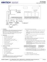
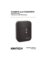
Installation
1. Insert the nylon standoffs into the back panel of the
cabinet.
Note: Make sure the cabinet is in the upward
position and the tamper switch location is on the
right.
IMPORTANT: Don’t install the expansion modules
before checking their locations within the cabinet.
Trying to pull out the module from its standoffs
would damage it.
2. Secure the cabinet to the wall in the desired
location. Use appropriate wall anchors when
securing the cabinet to drywall, plaster, concrete,
brick or other surfaces.
3. Mount the expansion modules on their standoffs.
IMPORTANT: Make sure the modules terminal
blocks are positioned towards the center of the
cabinet.
4. Run the 91 cm (36 in) SPI cable, provided with the
cabinet, from the KT-400 controller or expansion
modules cabinet, through one of the knockouts, to
the 1
st
module in the new cabinet.

Telephone: 1 (450) 444-2030 • Toll free: 1-888-222-1560 • Fax: 1 (450) 444-2029 • Internet: www.kantech.com
Copyright © 2008 Tyco International Ltd. and its Respective Companies. All Rights Reserved • Specifications may change without notice.
Kantech and the Kantech logo are trademarks of Tyco International Ltd. and its Respective Companies.
2
KT-MOD-CAB
EXPANSION MODULES CABINET INSTALL SHEET
DN1806-0809
5. Run a 41 cm (16 in) SPI cable, provided with
every module, between the other modules.
6. If external power is required for the expansion
modules, run the ground and power cables
together through a separate knockout than
in Step 4. Connect the external power supply
to the expansion module as per their
corresponding install sheet.
7. Check the external power jumper position on
the expansion modules.
8. Run and connect the inputs or outputs
together through a separate knockout than
in Step 6 to each expansion module as per
the corresponding install sheet.
Note: Make sure that you don’t exceed the
conduits capacity according to the
specifications and the local building code.
9. Install and connect the tamper switch to the
tamper switch terminals on the KT-400
controller.
10. Power up all the expansion modules and verify
communication with the KT-400 controller.
11. Install the cabinet door.
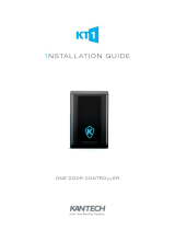
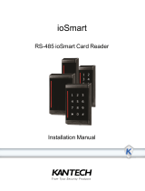
Example of KT-400 Controller Interconnection with Expansion Modules
/