P-WEE
®
INVERTER ARC WELDER
160TS
Service Manual
Version No: AA Issue Date: August 12, 2005 Manual No.: 0-4754
Operating Features:
Art # A-05870

WE APPRECIATE YOUR BUSINESS!
Congratulations on your new Thermal Arc product. We are proud
to have you as our customer and will strive to provide you with
the best service and reliability in the industry. This product is backed
by our extensive warranty and world-wide service network. To
locate your nearest distributor or service agency call
1-800-752-7621, or visit us on the web at www.Thermalarc.com.
This Operating Manual has been designed to instruct you on the
correct use and operation of your Thermal Arc product. Your
satisfaction with this product and its safe operation is our ultimate
concern. Therefore please take the time to read the entire manual,
especially the Safety Precautions. They will help you to avoid
potential hazards that may exist when working with this product.
YOU ARE IN GOOD COMPANY!
The Brand of Choice for Contractors and Fabricators Worldwide.
Thermal Arc is a Global Brand of Arc Welding Products for
Thermadyne Industries Inc. We manufacture and supply to major
welding industry sectors worldwide including; Manufacturing,
Construction, Mining, Automotive, Aerospace, Engineering, Rural
and DIY/Hobbyist.
We distinguish ourselves from our competition through market-
leading, dependable products that have stood the test of time. We
pride ourselves on technical innovation, competitive prices,
excellent delivery, superior customer service and technical support,
together with excellence in sales and marketing expertise.
Above all, we are committed to develop technologically advanced
products to achieve a safer working environment within the welding
industry.

WARNINGS
Read and understand this entire Manual and your employer’s safety practices before installing,
operating, or servicing the equipment.
While the information contained in this Manual represents the Manufacturer's best judgement,
the Manufacturer assumes no liability for its use.
P-Wee 160TS Inverter Arc Welding Power Supply
Instruction Manual Number 0-4754 for:
Spec Number 103067
Published by:
Thermal Dynamics Corporation
82 Benning Street
West Lebanon, New Hampshire, USA 03784
(603) 298-5711
www.thermalarc.com
Copyright 2001 by
Thermal Dynamics Corporation
All rights reserved.
Reproduction of this work, in whole or in part, without written permission of the pub-
lisher is prohibited.
The publisher does not assume and hereby disclaims any liability to any party for any
loss or damage caused by any error or omission in this Manual, whether such error
results from negligence, accident, or any other cause.
Publication Date: August 12, 2005
Record the following information for Warranty purposes:
Where Purchased: ___________________________________
Purchase Date: ___________________________________
Equipment Serial #: ___________________________________
i

TABLE OF CONTENTS
SECTION 1:
SAFETY INSTRUCTIONS AND WARNINGS ....................................................... 1-1
1.01 Arc Welding Hazards ...................................................................................... 1-1
1.02 PRINCIPAL SAFETY STANDARDS .................................................................. 1-5
1.03 PRECAUTIONS DE SECURITE EN SOUDAGE A L’ARC .................................... 1-6
1.04 Dangers relatifs au soudage à l’arc................................................................. 1-6
1.05 PRINCIPALES NORMES DE SECURITE ........................................................ 1-10
1.06 LIMITED WARRANTY ................................................................................... 1-11
SECTION 2:
INTRODUCTION ...................................................................................... 2-1
2.01 Scope of Manual ............................................................................................ 2-1
2.02 General Service Philosophy ............................................................................ 2-1
2.03 Service Responsibilities.................................................................................. 2-1
2.04 Symbol Chart ................................................................................................. 2-2
2.05 160TS Inverter Arc Welder Description .......................................................... 2-3
2.06 Functional Block Diagrams ............................................................................. 2-3
2.07 Specifications ................................................................................................. 2-4
2.08 Transporting Methods .................................................................................... 2-5
2.09 Duty Cycle ...................................................................................................... 2-5
SECTION 3:
INSTALLATION ....................................................................................... 3-1
3.01 Environment ................................................................................................... 3-1
3.02 Location ......................................................................................................... 3-1
3.03 Electrical Input Connections ........................................................................... 3-1
3.04 Electrical Input Requirements ........................................................................ 3-1
3.05 High Frequency Introduction .......................................................................... 3-4
3.06 High Frequency Interference .......................................................................... 3-4

TABLE OF CONTENTS (continued)TABLE OF CONTENTS
SECTION 4:
OPERATION ........................................................................................... 4-1
4.01 Controls.......................................................................................................... 4-1
4.02 Weld Parameters and Descriptions ................................................................ 4-4
4.03 Weld Parameters ............................................................................................ 4-5
4.04 Weld Process selection .................................................................................. 4-6
4.05 Power Source Features................................................................................... 4-7
4.06 General Set-Up ............................................................................................... 4-8
4.07 SEQUENCE OF OPERATION ............................................................................ 4-9
4.08 Stick Welding Setup ..................................................................................... 4-10
4.09 HF TIG & Lift TIG Welding Setup .................................................................. 4-10
4.10 Slope Mode Sequence Description ............................................................... 4-11
4.11 Pulse Controls .............................................................................................. 4-12
4.12 Switching VRD On/Off .................................................................................. 4-13
4.13 SEQUENCE TIMING DIAGRAMS................................................................... 4-14
SECTION 5:
SERVICE .............................................................................................. 5-1
5.01 Routine Maintenance ...................................................................................... 5-1
5.02 Basic Troubleshooting .................................................................................... 5-1
5.03 TIG Welding Problems ................................................................................... 5-2
5.04 Stick Welding Problems ................................................................................. 5-4
5.05 Power Source Problems ................................................................................. 5-6
5.06 VOLTAGE REDUCTION DEVICE (VRD) ............................................................ 5-7
5.07 POWER SOURCE ERROR CODES................................................................... 5-8

TABLE OF CONTENTS
SECTION 6:
ADVANCED TROUBLESHOOTING .................................................................. 6-1
6.01 System-Level Fault Isolation .......................................................................... 6-2
6.02 Verification and Remedy to the Indicated Error Codes ................................... 6-4
6.03 Verification and Remedy to Failures without Indication Codes ....................... 6-7
6.04 Preparation of Fault Isolation Tests .............................................................. 6-10
6.05 Verification of the power input circuitry. ....................................................... 6-10
6.06 Power Supply Voltage Test ........................................................................... 6-12
6.07 Verification of the Cooling Fan1 and Drive Circuitry ..................................... 6-14
6.08 Verification of the Solenoid Valve and Drive Circuitry. .................................. 6-16
6.09 Verification of No-load voltage (No OCV) ..................................................... 6-17
6.10 Output Load Test .......................................................................................... 6-18
6.11 Preparation for Subsystem Test and Replacement procedures .................... 6-19
6.12 PCB1 Replacement Procedure...................................................................... 6-23
6.13 PCB2 Replacement Procedure...................................................................... 6-25
6.14 PCB4 Replacement Procedure...................................................................... 6-28
6.15 PCB5 and PCB6 Replacement Procedure ..................................................... 6-31
6.16 Switch, S1 Replacement Procedure ............................................................. 6-34
6.17 Semiconductor Diode, D1 ............................................................................ 6-35
6.18 Semiconductor IGBT, Q1 .............................................................................. 6-37
6.19 Semiconductor Diode, D2, D3 ...................................................................... 6-39
6.20 Thermistors, TH1 ......................................................................................... 6-41
6.21 Coupling Coil, CC.......................................................................................... 6-42
6.22 Reactor, L1 ................................................................................................... 6-44
6.23 Transformer, T1 ............................................................................................ 6-46
6.24 Hall Current Transformer (HCT), CT1 ........................................................... 6-49
6.25 FAN1 Replacement Procedure ...................................................................... 6-50
6.26 HF. UNIT Replacement Procedure ................................................................ 6-51
6.27 Current-limiting Resistor for HF.UNIT, R2..................................................... 6-53
6.28 Gas Valve, SOL Replacement Procedure ...................................................... 6-54
SECTION 7:
PARTS LIST .......................................................................................... 7-1
7.01 Equipment Identification................................................................................. 7-1
7.02 How To Use This Parts List ............................................................................ 7-1
7.03 Parts List ........................................................................................................ 7-2

TABLE OF CONTENTS (continued)TABLE OF CONTENTS
APPENDIX 1: GENERAL INFORMATION ................................................................. A-1
APPENDIX 2: INTERCONNECT DIAGRAM SERIAL NUMBERS XXXXXXA AND EARLIER ......... A-2
APPENDIX 3: INTERCONNECT DIAGRAM SERIAL NUMBERS XXXXXXA103067 AND LATER ... A-4
APPENDIX 4: HARDWARE ................................................................................ A-6
APPENDIX 5: AUTOMATION .............................................................................. A-8
APPENDIX 6: DIODE TESTING BASICS ................................................................. A-10
Page is loading ...

P-WEE 160TS
1-1
August 12, 2005
1.01 Arc Welding Hazards
WARNING
ELECTRIC SHOCK can kill.
Touching live electrical parts can cause fatal
shocks or severe burns. The electrode and
work circuit is electrically live whenever the
output is on. The input power circuit and
machine internal circuits are also live when
power is on. In semiautomatic or automatic
wire welding, the wire, wire reel, drive roll
housing, and all metal parts touching the
welding wire are electrically live. Incorrectly
installed or improperly grounded equipment
is a hazard.
1. Do not touch live electrical parts.
2. Wear dry, hole-free insulating gloves and body
protection.
3. Insulate yourself from work and ground using dry
insulating mats or covers.
4. Disconnect input power or stop engine before
installing or servicing this equipment. Lock input
power disconnect switch open, or remove line fuses
so power cannot be turned on accidentally.
5. Properly install and ground this equipment according
to its Owner’s Manual and national, state, and local
codes.
6. Turn off all equipment when not in use. Disconnect
power to equipment if it will be left unattended or out
of service.
7. Use fully insulated electrode holders. Never dip holder
in water to cool it or lay it down on the ground or the
work surface. Do not touch holders connected to two
welding machines at the same time or touch other
people with the holder or electrode.
8. Do not use worn, damaged, undersized, or poorly
spliced cables.
9. Do not wrap cables around your body.
10.Ground the workpiece to a good electrical (earth)
ground.
SECTION 1:
SAFETY INSTRUCTIONS AND WARNINGS
WARNING
PROTECT YOURSELF AND OTHERS FROM POSSIBLE SERIOUS INJURY OR DEATH. KEEP CHILDREN AWAY.
PACEMAKER WEARERS KEEP AWAY UNTIL CONSULTING YOUR DOCTOR. DO NOT LOSE THESE INSTRUCTIONS.
READ OPERATING/INSTRUCTION MANUAL BEFORE INSTALLING, OPERATING OR SERVICING THIS EQUIPMENT.
Welding products and welding processes can cause serious injury or death, or damage to other equipment or property,
if the operator does not strictly observe all safety rules and take precautionary actions.
Safe practices have developed from past experience in the use of welding and cutting. These practices must be
learned through study and training before using this equipment. Some of these practices apply to equipment
connected to power lines; other practices apply to engine driven equipment. Anyone not having extensive
training in welding and cutting practices should not attempt to weld.
Safe practices are outlined in the American National Standard Z49.1 entitled:
SAFETY IN WELDING AND CUTTING.
This publication and other guides to what you should learn before operating this equipment are listed at the end of
these safety precautions. HAVE ALL INSTALLATION, OPERATION, MAINTENANCE, AND REPAIR WORK PERFORMED
ONLY BY QUALIFIED PEOPLE.

P-WEE 160TS
1-2
August 12, 2005
11.Do not touch electrode while in contact with the work
(ground) circuit.
12.Use only well-maintained equipment. Repair or replace
damaged parts at once.
13.In confined spaces or damp locations, do not use a
welder with AC output unless it is equipped with a
voltage reducer. Use equipment with DC output.
14.Wear a safety harness to prevent falling if working
above floor level.
15.Keep all panels and covers securely in place.
WARNING
ARC RAYS can burn eyes and skin; NOISE can
damage hearing.
Arc rays from the welding process produce
intense heat and strong ultraviolet rays that
can burn eyes and skin. Noise from some
processes can damage hearing.
1. Wear a welding helmet fitted with a proper shade of
filter (see ANSI Z49.1 listed in Safety Standards) to
protect your face and eyes when welding or watching.
2. Wear approved safety glasses. Side shields
recommended.
3. Use protective screens or barriers to protect others
from flash and glare; warn others not to watch the
arc.
4. Wear protective clothing made from durable, flame-
resistant material (wool and leather) and foot
protection.
5. Use approved ear plugs or ear muffs if noise level is
high.
WARNING
FUMES AND GASES can be hazardous to your
health.
Welding produces fumes and gases. Breathing
these fumes and gases can be hazardous to
your health.
1. Keep your head out of the fumes. Do not breath the
fumes.
2. If inside, ventilate the area and/or use exhaust at the
arc to remove welding fumes and gases.
3. If ventilation is poor, use an approved air-supplied
respirator.
4. Read the Material Safety Data Sheets (MSDSs) and
the manufacturer’s instruction for metals,
consumables, coatings, and cleaners.
5. Work in a confined space only if it is well ventilated,
or while wearing an air-supplied respirator. Shielding
gases used for welding can displace air causing injury
or death. Be sure the breathing air is safe.
Welding or cutting Electrode Size Filter Welding or cutting Electrode Size Filter
Torch soldering 2
Gas metal-arc
Torch brazing 3 or 4 Non-ferrous base metal All 11
Oxygen Cutting
Ferrous base metal All 12
Light Under 1 in., 25 mm 3 or 4 Gas tungsten arc welding All 12
Medium 1 to 6 in., 25-150 mm 4 or 5 (TIG) All 12
Heavy Over 6 in., 150 mm 5 or 6 Atomic hydrogen welding All 12
Ga s w e lding
Carbon arc welding All 12
Light Under 1/8 in., 3 mm 4 or 5 Plasma arc welding
Medium 1/8 to 1/2 in., 3-12 mm 5 or 6
Carbon arc air gouging
Heavy Over 1/2 in., 12 mm 6 or 8 Light 12
Shielded metal-arc
Under 5/32 in., 4 mm 10 Heavy 14
5/32 to 1/4 in., 12
Plasma arc cutting
Over 1/4 in., 6.4 mm 14 Light Under 300 Amp 9
Medium 300 to 400 Amp 12
Heavy Over 400 Amp 14
Eye protection filter shade selector for welding or cutting
(goggles or helmet), from AWS A6.2-73.

P-WEE 160TS
1-3
August 12, 2005
6. Do not weld in locations near degreasing, cleaning, or
spraying operations. The heat and rays of the arc can
react with vapors to form highly toxic and irritating
gases.
7. Do not weld on coated metals, such as galvanized,
lead, or cadmium plated steel, unless the coating is
removed from the weld area, the area is well ventilated,
and if necessary, while wearing an air-supplied
respirator. The coatings and any metals containing
these elements can give off toxic fumes if welded.
WARNING
WELDING can cause fire or explosion.
Sparks and spatter fly off from the welding
arc. The flying sparks and hot metal, weld
spatter, hot workpiece, and hot equipment can
cause fires and burns. Accidental contact of
electrode or welding wire to metal objects can
cause sparks, overheating, or fire.
1. Protect yourself and others from flying sparks and
hot metal.
2. Do not weld where flying sparks can strike flammable
material.
3. Remove all flammables within 35 ft (10.7 m) of the
welding arc. If this is not possible, tightly cover them
with approved covers.
4. Be alert that welding sparks and hot materials from
welding can easily go through small cracks and
openings to adjacent areas.
5. Watch for fire, and keep a fire extinguisher nearby.
6. Be aware that welding on a ceiling, floor, bulkhead, or
partition can cause fire on the hidden side.
7. Do not weld on closed containers such as tanks or
drums.
8. Connect work cable to the work as close to the welding
area as practical to prevent welding current from
traveling long, possibly unknown paths and causing
electric shock and fire hazards.
9. Do not use welder to thaw frozen pipes.
10.Remove stick electrode from holder or cut off welding
wire at contact tip when not in use.
WARNING
FLYING SPARKS AND HOT METAL can cause
injury.
Chipping and grinding cause flying metal. As
welds cool, they can throw off slag.
1. Wear approved face shield or safety goggles. Side
shields recommended.
2. Wear proper body protection to protect skin.
WARNING
CYLINDERS can explode if damaged.
Shielding gas cylinders contain gas under high
pressure. If damaged, a cylinder can explode.
Since gas cylinders are normally part of the
welding process, be sure to treat them
carefully.
1. Protect compressed gas cylinders from excessive heat,
mechanical shocks, and arcs.
2. Install and secure cylinders in an upright position by
chaining them to a stationary support or equipment
cylinder rack to prevent falling or tipping.
3. Keep cylinders away from any welding or other
electrical circuits.
4. Never allow a welding electrode to touch any cylinder.
5. Use only correct shielding gas cylinders, regulators,
hoses, and fittings designed for the specific
application; maintain them and associated parts in
good condition.
6. Turn face away from valve outlet when opening
cylinder valve.
7. Keep protective cap in place over valve except when
cylinder is in use or connected for use.
8. Read and follow instructions on compressed gas
cylinders, associated equipment, and CGA publication
P-1 listed in Safety Standards.

P-WEE 160TS
1-4
August 12, 2005
WARNING
Engines can be dangerous.
WARNING
ENGINE EXHAUST GASES can kill.
Engines produce harmful exhaust gases.
1. Use equipment outside in open, well-ventilated areas.
2. If used in a closed area, vent engine exhaust outside
and away from any building air intakes.
WARNING
ENGINE FUEL can cause fire or explosion.
Engine fuel is highly flammable.
1. Stop engine before checking or adding fuel.
2. Do not add fuel while smoking or if unit is near any
sparks or open flames.
3. Allow engine to cool before fueling. If possible, check
and add fuel to cold engine before beginning job.
4. Do not overfill tank — allow room for fuel to expand.
5. Do not spill fuel. If fuel is spilled, clean up before
starting engine.
WARNING
MOVING PARTS can cause injury.
Moving parts, such as fans, rotors, and belts can cut
fingers and hands and catch loose clothing.
1. Keep all doors, panels, covers, and guards closed
and securely in place.
2. Stop engine before installing or connecting unit.
3. Have only qualified people remove guards or
covers for maintenance and troubleshooting as
necessary.
4. To prevent accidental starting during servicing,
disconnect negative (-) battery cable from battery.
5. Keep hands, hair, loose clothing, and tools away
from moving parts.
6. Reinstall panels or guards and close doors when
servicing is finished and before starting engine.
WARNING
SPARKS can cause BATTERY GASES TO
EXPLODE; BATTERY ACID can burn eyes and
skin.
Batteries contain acid and generate explosive gases.
1. Always wear a face shield when working on a battery.
2. Stop engine before disconnecting or connecting
battery cables.
3. Do not allow tools to cause sparks when working on
a battery.
4. Do not use welder to charge batteries or jump start
vehicles.
5. Observe correct polarity (+ and –) on batteries.
WARNING
STEAM AND PRESSURIZED HOT COOLANT
can burn face, eyes, and skin.
The coolant in the radiator can be very hot
and under pressure.
1. Do not remove radiator cap when engine is hot. Allow
engine to cool.
2. Wear gloves and put a rag over cap area when
removing cap.
3. Allow pressure to escape before completely removing
cap.

P-WEE 160TS
1-5
August 12, 2005
WARNING
This product, when used for welding or
cutting, produces fumes or gases which
contain chemicals know to the State of
California to cause birth defects and, in some
cases, cancer. (California Health & Safety code
Sec. 25249.5 et seq.)
NOTE
Considerations About Welding And The Effects
of Low Frequency Electric and Magnetic Fields
The following is a quotation from the General Conclusions
Section of the U.S. Congress, Office of Technology
Assessment,
Biological Effects of Power
Frequency Electric & Magnetic Fields - Background Paper,
OTA-BP-E-63 (Washington, DC: U.S. Government Printing
Office, May 1989): “...there is now a very large volume of
scientific findings based on experiments at the cellular
level and from studies with animals and people which
clearly establish that low frequency magnetic fields and
interact with, and produce changes in, biological systems.
While most of this work is of very high quality, the results
are complex. Current scientific understanding does not
yet allow us to interpret the evidence in a single coherent
framework. Even more frustrating, it does not yet allow
us to draw definite conclusions about questions of
possible risk or to offer clear science-based advice on
strategies to minimize or avoid potential risks.”
To reduce magnetic fields in the workplace, use the
following procedures.
1. Keep cables close together by twisting or taping
them.
2. Arrange cables to one side and away from the
operator.
3. Do not coil or drape cable around the body.
4. Keep welding power source and cables as far away
from body as practical.
ABOUT PACEMAKERS:
The above procedures are among those also
normally recommended for pacemaker
wearers. Consult your doctor for complete
information.
1.02 PRINCIPAL SAFETY STANDARDS
Safety in Welding and Cutting, ANSI Standard Z49.1, from
American Welding Society, 550 N.W. LeJeune Rd., Miami,
FL 33126.
Safety and Health Standards, OSHA 29 CFR 1910, from
Superintendent of Documents, U.S. Government Printing
Office, Washington, D.C. 20402.
Recommended Safe Practices for the Preparation for
Welding and Cutting of Containers That Have Held
Hazardous Substances, American Welding Society
Standard AWS F4.1, from American Welding Society, 550
N.W. LeJeune Rd., Miami, FL 33126.
National Electrical Code, NFPA Standard 70, from National
Fire Protection Association, Batterymarch Park, Quincy,
MA 02269.
Safe Handling of Compressed Gases in Cylinders, CGA
Pamphlet P-1, from Compressed Gas Association, 1235
Jefferson Davis Highway, Suite 501, Arlington, VA 22202.
Code for Safety in Welding and Cutting, CSA Standard
W117.2, from Canadian Standards Association, Standards
Sales, 178 Rexdale Boulevard, Rexdale, Ontario, Canada
M9W 1R3.
Safe Practices for Occupation and Educational Eye and
Face Protection, ANSI Standard Z87.1, from American
National Standards Institute, 1430 Broadway, New York,
NY 10018.
Cutting and Welding Processes, NFPA Standard 51B, from
National Fire Protection Association, Batterymarch Park,
Quincy, MA 02269.
Page is loading ...
Page is loading ...
Page is loading ...
Page is loading ...

P-WEE 160TS
1-10
August 12, 2005
4. Pour empêcher un démarrage accidentel pendant
l’entretien, débranchez le câble d’accumulateur à la
borne négative.
5. N’approchez pas les mains ou les cheveux de pièces
en mouvement; elles peuvent aussi accrocher des
vêtements amples et des outils.
6. Réinstallez les capots ou les protecteurs et fermez les
portes après des travaux d’entretien et avant de faire
démarrer le moteur.
AVERTISSEMENT
DES ETINCELLES PEUVENT FAIRE EXPLOSER
UN ACCUMULATEUR; L’ELECTROLYTE D’UN
ACCUMU-LATEUR PEUT BRULER LA PEAU ET
LES YEUX.
Les accumulateurs contiennent de l’électrolyte
acide et dégagent des vapeurs explosives.
1. Portez toujours un écran facial en travaillant sur un
accumu-lateur.
2. Arrêtez le moteur avant de connecter ou de
déconnecter des câbles d’accumulateur.
3. N’utilisez que des outils anti-étincelles pour travailler
sur un accumulateur.
4. N’utilisez pas une source de courant de soudage pour
charger un accumulateur ou survolter
momentanément un véhicule.
5. Utilisez la polarité correcte (+ et –) de l’accumulateur.
AVERTISSEMENT
LA VAPEUR ET LE LIQUIDE DE
REFROIDISSEMENT BRULANT SOUS
PRESSION PEUVENT BRULER LA PEAU ET
LES YEUX.
Le liquide de refroidissement d’un radiateur
peut être brûlant et sous pression.
1. N’ôtez pas le bouchon de radiateur tant que le moteur
n’est pas refroidi.
2. Mettez des gants et posez un torchon sur le bouchon
pour l’ôter.
3. Laissez la pression s’échapper avant d’ôter
complètement le bouchon.
1.05 PRINCIPALES NORMES DE
SECURITE
Safety in Welding and Cutting, norme ANSI Z49.1, American
Welding Society, 550 N.W. LeJeune Rd., Miami, FL 33128.
Safety and Health Standards, OSHA 29 CFR 1910, Superintendent
of Documents, U.S. Government Printing Office, Washington, D.C.
20402.
Recommended Safe Practices for the Preparation for Welding and
Cutting of Containers That Have Held Hazardous Substances,
norme AWS F4.1, American Welding Society, 550 N.W. LeJeune
Rd., Miami, FL 33128.
National Electrical Code, norme 70 NFPA, National Fire Protection
Association, Batterymarch Park, Quincy, MA 02269.
Safe Handling of Compressed Gases in Cylinders, document P-1,
Compressed Gas Association, 1235 Jefferson Davis Highway, Suite
501, Arlington, VA 22202.
Code for Safety in Welding and Cutting, norme CSA W117.2
Association canadienne de normalisation, Standards Sales, 276
Rexdale Boulevard, Rexdale, Ontario, Canada M9W 1R3.
Safe Practices for Occupation and Educational Eye and Face
Protection, norme ANSI Z87.1, American National Standards
Institute, 1430 Broadway, New York, NY 10018.
Cutting and Welding Processes, norme 51B NFPA, National Fire
Protection Association, Batterymarch Park, Quincy, MA 02269.

P-WEE 160TS
1-11
August 12, 2005
1.06 LIMITED WARRANTY
LIMITED WARRANTY: Thermal Arc®, Inc., A Thermadyne Company, hereafter, “Thermal Arc” warrants to customers of itsauthorized distributors
hereafter “Purchaser” that its products will be free of defects in workmanship or material. Should anyfailure to conform to this warranty appear within
the time period applicable to the Thermal Arc products as stated below, Thermal Arc shall, upon notification thereof and substantiation that the product
has been stored, installed, operated, and maintained in accordance with Thermal Arc’s specifications, instructions, recommendations and recognized
standard industry practice, and not subject to misuse, repair, neglect, alteration, or accident, correct such defects by suitable repair or replacement, at
Thermal Arc’s sole option, of any components or parts of the product determined by Thermal Arc to be defective.
THERMAL ARC MAKES NO OTHER WARRANTY, EXPRESS OR IMPLIED. THIS WARRANTY IS EXCLUSIVE AND IN LIEU OF ALL OTHERS, INCLUDING,
BUT NOT LIMITED TO ANY WARRANTY OF MERCHANTABILITY OR FITNESS FOR ANY PARTICULAR PURPOSE.
LIMITATION OF LIABILITY: THERMAL ARC SHALL NOT UNDER ANY CIRCUMSTANCES BE LIABLE FOR SPECIAL, INDIRECT OR CONSEQUENTIAL
DAMAGES, SUCH AS, BUT NOT LIMITED TO, LOST PROFITS AND BUSINESS INTERRUPTION. The remedies of the Purchaser set forth herein are
exclusive and the liability of Thermal Arc with respect to any contract, or anything done in connection therewith such as the performance or breach
thereof, or from the manufacture, sale, delivery, resale, or use of any goods covered by or furnished by Thermal Arc whether arising out of contract,
negligence, strict tort, or under any warranty, or otherwise, shall not, except as expressly provided herein, exceed the price of the goods upon which
such liability is based. No employee, agent, or representative of Thermal Arc is authorized to change this warranty in any way or grant any other
warranty.
PURCHASER’S RIGHTS UNDER THIS WARRANTY ARE VOID IF REPLACEMENT PARTS OR ACCESSORIES ARE USED WHICH IN THERMAL ARC’S SOLE
JUDGEMENT MAY IMPAIR THE SAFETY OR PERFORMANCE OF ANY THERMAL ARC PRODUCT. PURCHASER’S RIGHTS UNDER THIS WARRANTY ARE
VOID IF THE PRODUCT IS SOLD TO PURCHASER BY NON-AUTHORIZED PERSONS.
The warranty is effective for the time stated below beginning on the date that the authorized distributor delivers the products to the Purchaser.
Notwithstanding the foregoing, in no event shall the warranty period extend more than the time stated plus one year from the date Thermal Arc
delivered the product to the authorized distributor.
POWER SUPPLIES
ALL OTHER
LABOR
POWER SUPPLIES
MAIN POWER MAGNETICS (STATIC & ROTATING) 3 YEARS 3 YEAR
ORIGINAL MAIN POWER RECTIFIER 3 YEARS 3 YEAR
CONTROL PC BOARD 3 YEARS 3 YEAR
ALL OTHER CIRCUITS AND COMPONENTS INCLUDING BUT
NOT LIMITED TO: CONTACTORS, RELAYS, SOLENOIDS, PUMPS,
POWER SWITCHING SEMI-CONDUCTORS.
ENGINES: ENGINES ARE NOT WARRANTED BY THERMAL ARC,
ALTHOUGH MOST ARE WARRANTED BY THE ENGINE
MANUFACTURER. SEE THE ENGINE MANUFACTURE'S 1 YEAR 1 YEAR
WARRANTY FOR DETAILS.
CONSOLES, CONTROL EQUIPMENT, HEAT EXCHANGES
ACCESSORY EQUIPMENT
1 YEAR 1 YEAR
NOTE: Dragster 85® excluded from this policy. Refer to Dragster 85 warranty in Dragster 85 Owner’s Manual.
Warranty repairs or replacement claims under this limited warranty must be submitted to Thermal Arc by an authorized Thermal Arc repair facility
within thirty (30) days of purchaser’s notice of any Warranty Claim. No transportation costs of any kind will be paid under this warranty. Transportation
charges to send products to an authorized warranty repair facility shall be the responsibility of the Purchaser. All returned goods shall be at the
Purchaser’s risk and expense. This warranty supersedes all previous Thermal Arc warranties. Thermal Arc® is a Registered Trademark of Thermadyne
Industries Inc.
September 27, 2004

P-WEE 160TS
1-12
August 12, 2005

PRO-LITE 160TS
August 12, 2005
2-1
SECTION 2:
INTRODUCTION
2.01 Scope of Manual
This manual provides service instructions for the Thermal
Arc® 160TS Inverter Arc Welder. Information in this
edition is particularly applicable to the troubleshooting
and repair of the equipment. For information on operating
procedures, please refer to the 160TS Inverter Arc Welder
Operating Manual (430429-505).
NOTE
Service of this equipment is restricted to
properly trained service technicians familiar
with this equipment; unqualified personnel are
strictly cautioned against attempting repairs
or adjustments not covered in this manual, at
the risk of voiding the warranty.
Read both this manual and the Operating Manual
thoroughly. A complete understanding of the capabilities
and functions of the equipment will assure obtaining the
performance for which it was designed.
WARNING
There are extremely dangerous voltage and
power levels present inside this unit. Do not
attempt to diagnose or repair unless you have
had training in high power electronics
measurement and troubleshooting.
2.02 General Service Philosophy
Several key points are essential to properly support the
application and operation of this equipment.
A. Application
Confirm that the equipment is capable of handling
the application desired. Specifications supplied and
described in Subsection 2.08 of this manual.
B. Modifications
No physical or electrical modifications other than
selection of standard options and accessories are
to be made to this equipment.
C. Customer/Operator Responsibilities
It is the customer/operator’s responsibility to
maintain the equipment and peripheral accessories
provided by Thermal Dynamics in good operating
order in accordance with the procedures outlined
in the Operating Manual, and to protect the
equipment from accidental or malicious damage.
D. Repair Restrictions
The electronics consists of printed circuit board
assemblies which must be carefully handled, and
must be replaced as units. No replacement of printed
circuit solder-mounted components is allowed
except as noted in this manual.
If the Printed Circuit Board is to be returned, the
replaced Printed Circuit Board Assemblies must be
properly packaged in protective material and
returned intact per normal procedures.
2.03 Service Responsibilities
The Service Technician should be familiar with the
equipment and its capabilities and should be prepared to
recommend arrangements of components which will
provide the most efficient layout, utilizing the equipment
to its best possible advantage.
Maintenance work should be accomplished in a timely
manner. If problems are encountered, or the equipment
does not function as specified, contact:
Thermadyne, Inc.
Thermal Arc Technical Service Department
82 Benning Street
West Lebanon, New Hampshire, USA 03784
(603) 298-5711
http://www.thermadyne.com
Additional copies of this manual may be purchased by
contacting Thermal Arc at the address and phone number
given in the next section. Include the Owner’s Manual
number and equipment identification numbers.
Electronic copies of this manual can also be downloaded
at no charge in Acrobat PDF format by going to the
Thermal Arc web site listed below and clicking on the
Literature Library link:
http://www.thermalarc.com

PRO-LITE 160TS
2-2
August 12, 2005
2.04 Symbol Chart
Note that only some of these symbols will appear on your model.
Gas Tungsten Arc
Welding (GTAW)
Air Carbon Arc
Cutting (CAC-A)
Constant Current
Constant Voltage
Or Constant Potential
High Temperature
Fault Indication
Arc Force
Touch Start (GTAW)
Variable Inductance
Voltage Input
Single Phase
Three Phase
Three Phase Static
Frequency Converter-
Transformer-Rectifier
Dangerous Voltage
Off
On
Panel/Local
Shielded Metal
Arc Welding (SMAW)
Gas Metal Arc
Welding (GMAW)
Increase/Decrease
Circuit Breaker
AC Auxiliary Power
Remote
Duty Cycle
Percentage
Amperage
Voltage
Hertz (cycles/sec)
Frequency
Negative
Positive
Direct Current (DC)
Protective Earth
(Ground)
Line
Line Connection
Auxiliary Power
Receptacle Rating-
Auxiliary Power
Art # A-04130
115V 15A
t
t1
t2
%
X
IPM
MPM
t
V
Fuse
Wire Feed Function
Wire Feed Towards
Workpiece With
Output Voltage Off.
Preflow Time
Postflow Time
Spot Time
Spot Weld Mode
Continuous Weld
Mode
Press to initiate wirefeed and
welding, release to stop.
Purging Of Gas
Inches Per Minute
Meters Per Minute
Disturbance In
Ground System
Welding Gun
Burnback Time
Press and hold for preflow, release
to start arc. Press to stop arc, and
hold for preflow.
4 Step Trigger
Operation
2 Step Trigger
Operation

PRO-LITE 160TS
August 12, 2005
2-3
2.05 160TS Inverter Arc Welder
Description
The Thermal Arc Model 160TS is a self contained single-
phase DC arc welding power sources with Constant
Current (CC) output characteristics. This unit is equipped
with a Digital Volt/Amperage Meter, gas control valve, built
in Sloper and Pulser, lift arc starter, and high-frequency
arc starter for use with Gas Tungsten Arc Welding (GTAW),
Gas Tungsten Arc Welding-Pulsed (GTAW-P) Gas
Tungsten Arc Welding-Sloped (GTAW-S), and Shielded
Metal Arc Welding (SMAW) processes. The power source
is totally enclosed in an impact resistant, flame resistant
and nonconductive plastic case.
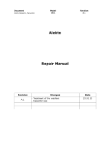
2.06 Functional Block Diagrams
Art # A-05870
Figure 2-1: 160TS Function Block Diagram

PRO-LITE 160TS
2-4
August 12, 2005
2.07 Specifications
160TS
DC STICK/LIFT TIG/HF TIG
Duty Cycle TIG 160A / 16.4V @ 35% 230VAC
130A / 15.2V @ 60% 230VAC
100A / 14V @ 100% 230VAC
85A / 13.4V @ 100% 115VAC
STICK 160A / 26.4V @ 35% 230VAC
130A / 25.2V @ 60% 230VAC
100A / 24V @ 100% 230VAC
50A / 23.4V @ 100% 115VAC
TIG 1 – 160 (230V), 1 – 85 (115V)
STICK 1 – 160 (230V), 1 – 85 (115V)
64V
5.12” (130mm)
10.24” (260mm)
12.60” (320mm)
18.95 lb. 8.6 kg
Single Phase 115VAC Single phase 230VAC
85A 160A
23.4V 26.4V
100% 35%
4.4 8.7
2.4 5.2
0.2
0.1
Amperage Draw @ Rated Load No Load
29 1.5
34 1.0
MODEL
Description
Open Circuit Voltage
Dimensions
Width
Height
Length
Weight
Output @ Rated Load
Rated Input Voltage
Output Amperes
Output Volts
230V
Output Current Range
KVA
KW
Input Volts Single Phase
115V
Duty Cycle
KVA
KW
Output @ No Load
Table 2-1: Specifications for 160TS

PRO-LITE 160TS
August 12, 2005
2-5
2.08 Transporting Methods
These units are equipped with a handle for carrying
purposes.
WARNING
ELECTRIC SHOCK can kill. DO NOT TOUCH
live electrical parts. Disconnect input power
conductors from de-energized supply line
before moving the welding power source.
WARNING
FALLING EQUIPMENT can cause serious
personal injury and equipment damage.
Lift unit with handle on top of case.
Use handcart or similar device of adequate capacity.
If using a fork lift vehicle, place and secure unit on a proper
skid before transporting.
2.09 Duty Cycle
The duty cycle of a welding power source is the percentage
of a ten (10) minute period that it can be operated at a
given output without causing overheating and damage to
the unit. If the welding amperes decrease, the duty cycle
increases. If the welding amperes are increased beyond
the rated output, the duty cycle will decrease.
WARNING
Exceeding the duty cycle ratings will cause the
thermal overload protection circuit to become
energized and shut down the output until the
unit has cooled to normal operating
temperature.
CAUTION
Continually exceeding the duty cycle ratings
can cause damage to the welding power
source and will void the manufactures
warranty.
NOTE
Due to variations that can occur in
manufactured products, claimed performance,
voltages, ratings, all capacities,
measurements, dimensions and weights
quoted are approximate only. Achievable
capacities and ratings in use and operation will
depend upon correct installation, use,
applications, maintenance and service.
Page is loading ...
Page is loading ...
Page is loading ...
Page is loading ...
Page is loading ...
Page is loading ...
Page is loading ...
Page is loading ...
Page is loading ...
Page is loading ...
Page is loading ...
Page is loading ...
Page is loading ...
Page is loading ...
Page is loading ...
Page is loading ...
Page is loading ...
Page is loading ...
Page is loading ...
Page is loading ...
Page is loading ...
Page is loading ...
Page is loading ...
Page is loading ...
Page is loading ...
Page is loading ...
Page is loading ...
Page is loading ...
Page is loading ...
Page is loading ...
Page is loading ...
Page is loading ...
Page is loading ...
Page is loading ...
Page is loading ...
Page is loading ...
Page is loading ...
Page is loading ...
Page is loading ...
Page is loading ...
Page is loading ...
Page is loading ...
Page is loading ...
Page is loading ...
Page is loading ...
Page is loading ...
Page is loading ...
Page is loading ...
Page is loading ...
Page is loading ...
Page is loading ...
Page is loading ...
Page is loading ...
Page is loading ...
Page is loading ...
Page is loading ...
Page is loading ...
Page is loading ...
Page is loading ...
Page is loading ...
Page is loading ...
Page is loading ...
Page is loading ...
Page is loading ...
Page is loading ...
Page is loading ...
Page is loading ...
Page is loading ...
Page is loading ...
Page is loading ...
Page is loading ...
Page is loading ...
Page is loading ...
Page is loading ...
Page is loading ...
Page is loading ...
Page is loading ...
Page is loading ...
Page is loading ...
Page is loading ...
Page is loading ...
Page is loading ...
Page is loading ...
Page is loading ...
Page is loading ...
Page is loading ...
Page is loading ...
Page is loading ...
Page is loading ...
Page is loading ...
Page is loading ...
Page is loading ...
Page is loading ...
Page is loading ...
Page is loading ...
Page is loading ...
Page is loading ...
Page is loading ...
Page is loading ...
Page is loading ...
Page is loading ...
Page is loading ...
Page is loading ...
Page is loading ...
Page is loading ...
/