Page is loading ...

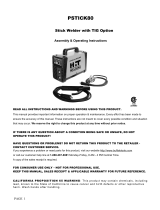
ARCMASTER
Version No: 1 Issue Date: November 1, 2005 Manual No.: 0-4820
Operating Features:
INVERTER ARC WELDER
160 S
Art # A-07082
Operating Manual

WARNINGS
Read and understand this entire Manual and your employer’s safety practices before installing,
operating, or servicing the equipment.
While the information contained in this Manual represents the Manufacturer's best judgement,
the Manufacturer assumes no liability for its use.
160S 460V Arc Master Inverter Arc Welder
Instruction Manual Number 0-4820 for:
Spec Number 10-3090
Published by:
Thermadyne Industries Inc.
82 Benning Street
West Lebanon, New Hampshire, USA 03784
(603) 298-5711
www.thermalarc.com
Copyright 2006 by
Thermadyne Industries Inc.
All rights reserved.
Reproduction of this work, in whole or in part, without written permission of the pub-
lisher is prohibited.
The publisher does not assume and hereby disclaims any liability to any party for any
loss or damage caused by any error or omission in this Manual, whether such error
results from negligence, accident, or any other cause.
Publication Date: May 5, 2006
Record the following information for Warranty purposes:
Where Purchased: ___________________________________
Purchase Date: ___________________________________
Equipment Serial #: ___________________________________
i

TABLE OF CONTENTS
SECTION 1:
SAFETY INSTRUCTIONS AND WARNINGS ....................................................... 1-1
1.01 Arc Welding Hazards ...................................................................................... 1-1
1.02 Principal Safety Standards ............................................................................. 1-4
1.03 Precautions de Securite en Soudage à l’Arc ................................................... 1-5
1.04 Dangers Relatifs au Soudage à l’Arc............................................................... 1-5
1.05 Principales Normes de Securite ..................................................................... 1-8
SECTION 2:
INTRODUCTION ...................................................................................... 2-1
2.01 How To Use This Manual ................................................................................ 2-1
2.02 Equipment Identification................................................................................. 2-1
2.03 Receipt Of Equipment..................................................................................... 2-1
2.04 Symbol Chart ................................................................................................. 2-2
2.05 Description ..................................................................................................... 2-3
2.06 Specifications ................................................................................................. 2-4
2.07 Functional Block Diagrams ............................................................................. 2-5
2.08 Transporting Methods .................................................................................... 2-5
SECTION 3:
INSTALLATION ...................................................................................... 3-1
3.01 Environment ................................................................................................... 3-1
3.02 Location ......................................................................................................... 3-1
3.03 Electrical Input Connections ........................................................................... 3-1
3.04 Electrical Input Requirements ........................................................................ 3-2
3.05 Input Power.................................................................................................... 3-3
3.06 Duty Cycle ...................................................................................................... 3-3
SECTION 4:
OPERATION .......................................................................................... 4-1
4.01 160 S Controls ............................................................................................... 4-1
4.02 Weld Parameter Description for the 160 S ..................................................... 4-3
4.03 Weld Parameters for the 160 S ...................................................................... 4-4
4.04 Power Source Features................................................................................... 4-4
4.05 Set-up for SMAW (STICK) and GTAW (TIG) ................................................... 4-5
4.06 Sequence of Operation ................................................................................... 4-6
4.07 Stick Welding ................................................................................................. 4-7
4.08 DC LIFT TIG Welding ...................................................................................... 4-7

TABLE OF CONTENTS (continued)TABLE OF CONTENTS
4.09 DC PANEL LIFT TIG Welding .......................................................................... 4-7
4.10 Basic TIG Welding Guide ................................................................................ 4-8
4.10.01 Electrode Polarity .............................................................................. 4-8
4.10.02 Tungsten Electrode Current Ranges .................................................. 4-8
4.10.03 Tungsten Electrode Types.................................................................. 4-8
4.10.04 Guide for Selecting Filler Wire Diameter............................................ 4-8
4.10.05 Shielding Gas Selection ..................................................................... 4-9
4.10.06 TIG Welding Parameters for Low Carbon & Low Alloy Steel Pipe ..... 4-9
4.10.07 Welding Parameters for Steel............................................................ 4-9
4.11 Basic Arc Welding Guide .............................................................................. 4-10
4.11.01 Electrode Polarity ............................................................................ 4-10
4.11.02 Effects of Stick Welding Various Materials ...................................... 4-10
SECTION 5:
SERVICE .............................................................................................. 5-1
5.01 Maintenance ................................................................................................... 5-1
5.02 Basic Troubleshooting .................................................................................... 5-3
5.03 TIG Welding Problems ................................................................................... 5-3
5.04 Stick Welding Problems ................................................................................. 5-6
5.05 Power Source Problems................................................................................. 5-8
5.06 Power Source Error Codes ............................................................................. 5-9
5.07 Voltage Reduction Device (VRD) .................................................................. 5-11
5.08 VRD Maintenance ......................................................................................... 5-11
5.09 Enabling and Disabling the VRD ................................................................... 5-12
SECTION 6:
PARTS LIST .......................................................................................... 6-1
6.01 Equipment Identification................................................................................. 6-1
6.02 How To Use This Parts List ............................................................................ 6-1
6.03 User Replaceable Parts .................................................................................. 6-2
APPENDIX 1: GENERAL INFORMATION ................................................................. A-1
APPENDIX 2: INTERCONNECT DIAGRAM ............................................................... A-2
LIMITED WARRANTY
WARRANTY SCHEDULE
GLOBAL CUSTOMER SERVICE CONTACT INFORMATION .......................... Inside Rear Cover

160 S INVERTER ARC WELDER
1-1
November 1, 2005
7. Use fully insulated electrode holders. Never dip holder in water to
cool it or lay it down on the ground or the work surface. Do not
touch holders connected to two welding machines at the same
time or touch other people with the holder or electrode.
8. Do not use worn, damaged, undersized, or poorly spliced cables.
9. Do not wrap cables around your body.
10. Ground the workpiece to a good electrical (earth) ground.
11. Do not touch electrode while in contact with the work (ground)
circuit.
12. Use only well-maintained equipment. Repair or replace damaged
parts at once.
13. In confined spaces or damp locations, do not use a welder with
AC output unless it is equipped with a voltage reducer. Use
equipment with DC output.
14. Wear a safety harness to prevent falling if working above floor
level.
15. Keep all panels and covers securely in place.
WARNING
ARC RAYS can burn eyes and skin; NOISE can damage
hearing. Arc rays from the welding process produce
intense heat and strong ultraviolet rays that can burn
eyes and skin. Noise from some processes can damage
hearing.
1. Wear a welding helmet fitted with a proper shade of filter (see
ANSI Z49.1 listed in Safety Standards) to protect your face and
eyes when welding or watching.
2. Wear approved safety glasses. Side shields recommended.
1.01 Arc Welding Hazards
WARNING
ELECTRIC SHOCK can kill.
Touching live electrical parts can cause fatal shocks or
severe burns. The electrode and work circuit is electrically
live whenever the output is on. The input power circuit
and machine internal circuits are also live when power
is on. In semiautomatic or automatic wire welding, the
wire, wire reel, drive roll housing, and all metal parts
touching the welding wire are electrically live. Incorrectly
installed or improperly grounded equipment is a hazard.
1. Do not touch live electrical parts.
2. Wear dry, hole-free insulating gloves and body protection.
3. Insulate yourself from work and ground using dry insulating mats
or covers.
4. Disconnect input power or stop engine before installing or
servicing this equipment. Lock input power disconnect switch
open, or remove line fuses so power cannot be turned on
accidentally.
5. Properly install and ground this equipment according to its Owner’s
Manual and national, state, and local codes.
6. Turn off all equipment when not in use. Disconnect power to
equipment if it will be left unattended or out of service.
SECTION 1:
SAFETY INSTRUCTIONS AND WARNINGS
!
WARNING
PROTECT YOURSELF AND OTHERS FROM POSSIBLE SERIOUS INJURY OR DEATH. KEEP CHILDREN AWAY. PACEMAKER WEARERS KEEP
AWAY UNTIL CONSULTING YOUR DOCTOR. DO NOT LOSE THESE INSTRUCTIONS. READ OPERATING/INSTRUCTION MANUAL BEFORE
INSTALLING, OPERATING OR SERVICING THIS EQUIPMENT.
Welding products and welding processes can cause serious injury or death, or damage to other equipment or property, if the operator does not
strictly observe all safety rules and take precautionary actions.
Safe practices have developed from past experience in the use of welding and cutting. These practices must be learned through study and
training before using this equipment. Some of these practices apply to equipment connected to power lines; other practices apply to engine
driven equipment. Anyone not having extensive training in welding and cutting practices should not attempt to weld.
Safe practices are outlined in the American National Standard Z49.1 entitled:
SAFETY IN WELDING AND CUTTING. This publication and other
guides to what you should learn before operating this equipment are listed at the end of these safety precautions. HAVE ALL INSTALLATION,
OPERATION, MAINTENANCE, AND REPAIR WORK PERFORMED ONLY BY QUALIFIED PEOPLE.

160 S INVERTER ARC WELDER
1-2
November 1, 2005
3. Use protective screens or barriers to protect others from flash
and glare; warn others not to watch the arc.
4. Wear protective clothing made from durable, flame-resistant
material (wool and leather) and foot protection.
5. Use approved ear plugs or ear muffs if noise level is high.
WARNING
FUMES AND GASES can be hazardous to your health.
Welding produces fumes and gases. Breathing these
fumes and gases can be hazardous to your health.
1. Keep your head out of the fumes. Do not breath the fumes.
2. If inside, ventilate the area and/or use exhaust at the arc to remove
welding fumes and gases.
3. If ventilation is poor, use an approved air-supplied respirator.
4. Read the Material Safety Data Sheets (MSDSs) and the
manufacturer’s instruction for metals, consumables, coatings, and
cleaners.
5. Work in a confined space only if it is well ventilated, or while
wearing an air-supplied respirator. Shielding gases used for
welding can displace air causing injury or death. Be sure the
breathing air is safe.
6. Do not weld in locations near degreasing, cleaning, or spraying
operations. The heat and rays of the arc can react with vapors to
form highly toxic and irritating gases.
7. Do not weld on coated metals, such as galvanized, lead, or
cadmium plated steel, unless the coating is removed from the
weld area, the area is well ventilated, and if necessary, while
wearing an air-supplied respirator. The coatings and any metals
containing these elements can give off toxic fumes if welded.
WARNING
WELDING can cause fire or explosion.
Sparks and spatter fly off from the welding arc. The flying
sparks and hot metal, weld spatter, hot workpiece, and
hot equipment can cause fires and burns. Accidental
contact of electrode or welding wire to metal objects
can cause sparks, overheating, or fire.
1. Protect yourself and others from flying sparks and hot metal.
2. Do not weld where flying sparks can strike flammable material.
3. Remove all flammables within 35 ft (10.7 m) of the welding arc.
If this is not possible, tightly cover them with approved covers.
4. Be alert that welding sparks and hot materials from welding can
easily go through small cracks and openings to adjacent areas.
5. Watch for fire, and keep a fire extinguisher nearby.
6. Be aware that welding on a ceiling, floor, bulkhead, or partition
can cause fire on the hidden side.
7. Do not weld on closed containers such as tanks or drums.
8. Connect work cable to the work as close to the welding area as
practical to prevent welding current from traveling long, possibly
unknown paths and causing electric shock and fire hazards.
9. Do not use welder to thaw frozen pipes.
10. Remove stick electrode from holder or cut off welding wire at
contact tip when not in use.
Welding or cutting Electrode Size Filter Welding or cutting Electrode Size Filter
Torch soldering 2 Gas metal-arc
Torch brazing 3 or 4 Non-ferrous base metal All 11
Oxygen Cutting Ferrous base metal All 12
Light Under 1 in., 25 mm 3 or 4 Gas tungsten arc welding All 12
Medium 1 to 6 in., 25-150 mm 4 or 5 (TIG) All 12
Heavy Over 6 in., 150 mm 5 or 6 Atomic hydrogen welding All 12
Gas welding Carbon arc welding All 12
Light Under 1/8 in., 3 mm 4 or 5 Plasma arc welding
Medium 1/8 to 1/2 in., 3-12 mm 5 or 6 Carbon arc air gouging
Heavy Over 1/2 in., 12 mm 6 or 8 Light 12
Shielded metal-arc Under 5/32 in., 4 mm 10 Heavy 14
5/32 to 1/4 in., 12 Plasma arc cutting
Over 1/4 in., 6.4 mm 14 Light Under 300 Amp 9
Medium 300 to 400 Amp 12
Heavy Over 400 Amp 14
Eye protection filter shade selector for welding or cutting
(goggles or helmet), from AWS A6.2-73.

160 S INVERTER ARC WELDER
1-3
November 1, 2005
WARNING
FLYING SPARKS AND HOT METAL can cause injury.
Chipping and grinding cause flying metal. As welds cool,
they can throw off slag.
1. Wear approved face shield or safety goggles. Side shields
recommended.
2. Wear proper body protection to protect skin.
WARNING
CYLINDERS can explode if damaged.
Shielding gas cylinders contain gas under high pressure.
If damaged, a cylinder can explode. Since gas cylinders
are normally part of the welding process, be sure to treat
them carefully.
1. Protect compressed gas cylinders from excessive heat, mechanical
shocks, and arcs.
2. Install and secure cylinders in an upright position by chaining
them to a stationary support or equipment cylinder rack to prevent
falling or tipping.
3. Keep cylinders away from any welding or other electrical circuits.
4. Never allow a welding electrode to touch any cylinder.
5. Use only correct shielding gas cylinders, regulators, hoses, and
fittings designed for the specific application; maintain them and
associated parts in good condition.
6. Turn face away from valve outlet when opening cylinder valve.
7. Keep protective cap in place over valve except when cylinder is in
use or connected for use.
8. Read and follow instructions on compressed gas cylinders,
associated equipment, and CGA publication P-1 listed in Safety
Standards.
!
WARNING
Engines can be dangerous.
WARNING
ENGINE EXHAUST GASES can kill.
Engines produce harmful exhaust gases.
1. Use equipment outside in open, well-ventilated areas.
2. If used in a closed area, vent engine exhaust outside and away
from any building air intakes.
WARNING
ENGINE FUEL can cause fire or explosion.
Engine fuel is highly flammable.
1. Stop engine before checking or adding fuel.
2. Do not add fuel while smoking or if unit is near any sparks or
open flames.
3. Allow engine to cool before fueling. If possible, check and add
fuel to cold engine before beginning job.
4. Do not overfill tank — allow room for fuel to expand.
5. Do not spill fuel. If fuel is spilled, clean up before starting engine.
WARNING
MOVING PARTS can cause injury.
Moving parts, such as fans, rotors, and belts can cut fingers and hands
and catch loose clothing.
1. Keep all doors, panels, covers, and guards closed and
securely in place.
2. Stop engine before installing or connecting unit.
3. Have only qualified people remove guards or covers for
maintenance and troubleshooting as necessary.
4. To prevent accidental starting during servicing, disconnect
negative (-) battery cable from battery.
5. Keep hands, hair, loose clothing, and tools away from moving
parts.
6. Reinstall panels or guards and close doors when servicing
is finished and before starting engine.
WARNING
SPARKS can cause BATTERY GASES TO EXPLODE;
BATTERY ACID can burn eyes and skin.
Batteries contain acid and generate explosive gases.
1. Always wear a face shield when working on a battery.
2. Stop engine before disconnecting or connecting battery cables.
3. Do not allow tools to cause sparks when working on a battery.
4. Do not use welder to charge batteries or jump start vehicles.
5. Observe correct polarity (+ and –) on batteries.

160 S INVERTER ARC WELDER
1-4
November 1, 2005
WARNING
STEAM AND PRESSURIZED HOT COOLANT can burn
face, eyes, and skin.
The coolant in the radiator can be very hot and under
pressure.
1. Do not remove radiator cap when engine is hot. Allow engine to cool.
2. Wear gloves and put a rag over cap area when removing cap.
3. Allow pressure to escape before completely removing cap.
!
WARNING
This product, when used for welding or cutting, produces
fumes or gases which contain chemicals know to the
State of California to cause birth defects and, in some
cases, cancer. (California Health & Safety code Sec.
25249.5 et seq.)
NOTE
Considerations About Welding And The Effects of Low
Frequency Electric and Magnetic Fields
The following is a quotation from the General Conclusions Section of
the U.S. Congress, Office of Technology Assessment, Biological Effects
of Power Frequency Electric & Magnetic Fields - Background Paper,
OTA-BP-E-63 (Washington, DC: U.S. Government Printing Office, May
1989): “...there is now a very large volume of scientific findings based
on experiments at the cellular level and from studies with animals and
people which clearly establish that low frequency magnetic fields
interact with, and produce changes in, biological systems. While most
of this work is of very high quality, the results are complex. Current
scientific understanding does not yet allow us to interpret the evidence
in a single coherent framework. Even more frustrating, it does not yet
allow us to draw definite conclusions about questions of possible risk
or to offer clear science-based advice on strategies to minimize or
avoid potential risks.”
To reduce magnetic fields in the workplace, use the following
procedures:
1. Keep cables close together by twisting or taping them.
2. Arrange cables to one side and away from the operator.
3. Do not coil or drape cable around the body.
4. Keep welding power source and cables as far away from
body as practical.
ABOUT PACEMAKERS:
The above procedures are among those also normally
recommended for pacemaker wearers. Consult your
doctor for complete information.
1.02 Principal Safety Standards
Safety in Welding and Cutting, ANSI Standard Z49.1, from American
Welding Society, 550 N.W. LeJeune Rd., Miami, FL 33126.
Safety and Health Standards, OSHA 29 CFR 1910, from Superintendent
of Documents, U.S. Government Printing Office, Washington, D.C.
20402.
Recommended Safe Practices for the Preparation for Welding and
Cutting of Containers That Have Held Hazardous Substances, Ameri-
can Welding Society Standard AWS F4.1, from American Welding
Society, 550 N.W. LeJeune Rd., Miami, FL 33126.
National Electrical Code, NFPA Standard 70, from National Fire
Protection Association, Batterymarch Park, Quincy, MA 02269.
Safe Handling of Compressed Gases in Cylinders, CGA Pamphlet P-
1, from Compressed Gas Association, 1235 Jefferson Davis Highway,
Suite 501, Arlington, VA 22202.
Code for Safety in Welding and Cutting, CSA Standard W117.2, from
Canadian Standards Association, Standards Sales, 178 Rexdale
Boulevard, Rexdale, Ontario, Canada M9W 1R3.
Safe Practices for Occupation and Educational Eye and Face Protec-
tion, ANSI Standard Z87.1, from American National Standards Insti-
tute, 1430 Broadway, New York, NY 10018.
Cutting and Welding Processes, NFPA Standard 51B, from National
Fire Protection Association, Batterymarch Park, Quincy, MA 02269.

160 S INVERTER ARC WELDER
1-8
November 1, 2005
1. Utilisez l’équipement à l’extérieur dans des aires ouvertes et bien
ventilées.
2. Si vous utilisez ces équipements dans un endroit confiné, les
fumées d’échappement doivent être envoyées à l’extérieur, loin
des prises d’air du bâtiment.
AVERTISSEMENT
LE CARBURANT PEUR CAUSER UN INCENDIE OU UNE
EXPLOSION.
Le carburant est hautement inflammable.
1. Arrêtez le moteur avant de vérifier le niveau e carburant ou de
faire le plein.
2. Ne faites pas le plein en fumant ou proche d’une source d’étincelles
ou d’une flamme nue.
3. Si c’est possible, laissez le moteur refroidir avant de faire le plein
de carburant ou d’en vérifier le niveau au début du soudage.
4. Ne faites pas le plein de carburant à ras bord: prévoyez de l’espace
pour son expansion.
5. Faites attention de ne pas renverser de carburant. Nettoyez tout
carburant renversé avant de faire démarrer le moteur.
AVERTISSEMENT
DES PIECES EN MOUVEMENT PEUVENT CAUSER DES
BLESSURES.
Des pièces en mouvement, tels des ventilateurs, des
rotors et des courroies peuvent couper doigts et mains,
ou accrocher des vêtements amples.
1. Assurez-vous que les portes, les panneaux, les capots et les
protecteurs soient bien fermés.
2. Avant d’installer ou de connecter un système, arrêtez le moteur.
3. Seules des personnes qualifiées doivent démonter des protecteurs
ou des capots pour faire l’entretien ou le dépannage nécessaire.
4. Pour empêcher un démarrage accidentel pendant l’entretien,
débranchez le câble d’accumulateur à la borne négative.
5. N’approchez pas les mains ou les cheveux de pièces en
mouvement; elles peuvent aussi accrocher des vêtements amples
et des outils.
6. Réinstallez les capots ou les protecteurs et fermez les portes après
des travaux d’entretien et avant de faire démarrer le moteur.
AVERTISSEMENT
DES ETINCELLES PEUVENT FAIRE EXPLOSER UN
ACCUMULATEUR; L’ELECTROLYTE D’UN ACCUMU-
LATEUR PEUT BRULER LA PEAU ET LES YEUX.
Les accumulateurs contiennent de l’électrolyte acide et
dégagent des vapeurs explosives.
1. Portez toujours un écran facial en travaillant sur un accumu-lateur.
2. Arrêtez le moteur avant de connecter ou de déconnecter des câbles
d’accumulateur.
3. N’utilisez que des outils anti-étincelles pour travailler sur un
accumulateur.
4. N’utilisez pas une source de courant de soudage pour charger
un accumulateur ou survolter momentanément un véhicule.
5. Utilisez la polarité correcte (+ et –) de l’accumulateur.
AVERTISSEMENT
LA VAPEUR ET LE LIQUIDE DE REFROIDISSEMENT
BRULANT SOUS PRESSION PEUVENT BRULER LA
PEAU ET LES YEUX.
Le liquide de refroidissement d’un radiateur peut être
brûlant et sous pression.
1. N’ôtez pas le bouchon de radiateur tant que le moteur n’est pas
refroidi.
2. Mettez des gants et posez un torchon sur le bouchon pour l’ôter.
3. Laissez la pression s’échapper avant d’ôter complètement le
bouchon.
1.05 Principales Normes de Securite
Safety in Welding and Cutting, norme ANSI Z49.1, American Weld-
ing Society, 550 N.W. LeJeune Rd., Miami, FL 33128.
Safety and Health Standards, OSHA 29 CFR 1910, Superintendent of
Documents, U.S. Government Printing Office, Washington, D.C.
20402.
Recommended Safe Practices for the Preparation for Welding and
Cutting of Containers That Have Held Hazardous Substances, norme
AWS F4.1, American Welding Society, 550 N.W. LeJeune Rd., Miami,
FL 33128.
National Electrical Code, norme 70 NFPA, National Fire Protection
Association, Batterymarch Park, Quincy, MA 02269.
Safe Handling of Compressed Gases in Cylinders, document P-1,
Compressed Gas Association, 1235 Jefferson Davis Highway, Suite
501, Arlington, VA 22202.
Code for Safety in Welding and Cutting, norme CSA W117.2 Asso-
ciation canadienne de normalisation, Standards Sales, 276 Rexdale
Boulevard, Rexdale, Ontario, Canada M9W 1R3.
Safe Practices for Occupation and Educational Eye and Face Protec-
tion, norme ANSI Z87.1, American National Standards Institute, 1430
Broadway, New York, NY 10018.
Cutting and Welding Processes, norme 51B NFPA, National Fire Pro-
tection Association, Batterymarch Park, Quincy, MA 02269.

160 S INVERTER ARC WELDER
November 1, 2005
2-1
SECTION 2:
INTRODUCTION
2.01 How To Use This Manual
This Owner’s Manual applies to just specification or part
numbers listed on page i.
To ensure safe operation, read the entire manual, including
the chapter on safety instructions and warnings.
Throughout this manual, the words WARNING,
CAUTION, and NOTE may appear. Pay particular attention
to the information provided under these headings. These
special annotations are easily recognized as
follows:
!
WARNING
A WARNING gives information regarding
possible personal injury.
CAUTION
A CAUTION refers to possible equipment
damage.
NOTE
A NOTE offers helpful information concerning
certain operating procedures.
Additional copies of this manual may be purchased by
contacting Thermal Arc at the address and phone number
given in the inside back cover of this manual. Include the
Owner’s Manual number and equipment identification
numbers.
Electronic copies of this manual can also be downloaded
at no charge in Acrobat PDF format by going to the
Thermal Arc web site listed below and clicking on the
Literature Library link:
http://www.thermalarc.com
2.02 Equipment Identification
The unit’s identification number (specification or part
number), model, and serial number usually appear on a
nameplate attached to the control panel. In some cases,
the nameplate may be attached to the rear panel.
Equipment which does not have a control panel such as
gun and cable assemblies is identified only by the
specification or part number printed on the shipping
container. Record these numbers on the bottom of page
i for future reference.
2.03 Receipt Of Equipment
When you receive the equipment, check it against the
invoice to make sure it is complete and inspect the
equipment for possible damage due to shipping. If there
is any damage, notify the carrier immediately to file a
claim. Furnish complete information concerning damage
claims or shipping errors to the location in your area
listed in the inside back cover of this manual.
Include all equipment identification numbers as described
above along with a full description of the parts in error.
Move the equipment to the installation site before un-
crating the unit. Use care to avoid damaging the
equipment when using bars, hammers, etc., to un-crate
the unit.

160 S INVERTER ARC WELDER
2-2
November 1, 2005
2.04 Symbol Chart
Note that only some of these symbols will appear on your model.
Gas Tungsten Arc
Welding (GTAW)
Air Carbon Arc
Cutting (CAC-A)
Constant Current
Constant Voltage
Or Constant Potential
High Temperature
Fault Indication
Arc Force
Touch Start (GTAW)
Variable Inductance
Voltage Input
Single Phase
Three Phase
Three Phase Static
Frequency Converter-
Transformer-Rectifier
Dangerous Voltage
Off
On
Panel/Local
Shielded Metal
Arc Welding (SMAW)
Gas Metal Arc
Welding (GMAW)
Increase/Decrease
Circuit Breaker
AC Auxiliary Power
Remote
Duty Cycle
Percentage
Amperage
Voltage
Hertz (cycles/sec)
Frequency
Negative
Positive
Direct Current (DC)
Protective Earth
(Ground)
Line
Line Connection
Auxiliary Power
Receptacle Rating-
Auxiliary Power
Art # A-04130
115V 15A
t
t1
t2
%
X
IPM
MPM
t
V
Fuse
Wire Feed Function
Wire Feed Towards
Workpiece With
Output Voltage Off.
Preflow Time
Postflow Time
Spot Time
Spot Weld Mode
Continuous Weld
Mode
Press to initiate wirefeed and
welding, release to stop.
Purging Of Gas
Inches Per Minute
Meters Per Minute
Disturbance In
Ground System
Welding Gun
Burnback Time
Press and hold for preflow, release
to start arc. Press to stop arc, and
hold for preflow.
4 Step Trigger
Operation
2 Step Trigger
Operation

160 S INVERTER ARC WELDER
November 1, 2005
2-3
2.05 Description
The Thermal Arc™ Model 160 S inverter arc welder is a
self contained single-phase DC arc welding power source
with Constant Current (CC) output characteristics. This
unit is equipped with a Digital Volt/Amperage Meter and
lift arc starter, for use with Gas Tungsten Arc Welding
(GTAW) and Shielded Metal Arc Welding (SMAW)
processes. The power source is totally enclosed in an
impact resistant, flame resistant and non-conductive
plastic case.
NOTE
Volt-Ampere curves show the maximum
Voltage and Amperage output capabilities of
the welding power source. Curves of other
settings will fall between the curves shown.
160A
160A
5A (A)
(V)
OCV
18V
185A
160A25A (A)
(V)
OCV
10V
Art # A-05037
Figure 2-1: Model 160 S Volt-Ampere Curve

160 S INVERTER ARC WELDER
2-4
November 1, 2005
2.06 Specifications
Output Current TIG
Range STICK
No Load
1
Input Volts Single Phase
460V
Amperage Draw @ Rated Load
19
Output @ No Load
KVA
KW
0.2
0.1
KVA
KW
8.7
5.2
Output Volts
Duty Cycle
27V
40%
Rated Input Voltage
Output Amperes
Single Phase 460VAC
160A
Weight 18.3 lb. (8.3 kg)
Output @ Rated Load
5.12” (130mm)
10.24” (260mm)
14.18” (360mm)
Dimensions
Width
Height
Length
5 – 160
5 – 160
Open Circuit Voltage 64V
STICK 160A / 27V @ 40% 460VAC
130A / 26V @ 60% 460VAC
100A / 24V @ 100% 460VAC
Duty Cycle TIG 160A / 17V @ 40% 460VAC
130A / 16V @ 60% 460VAC
100A / 14V @ 100% 460VAC
MODEL 160S
Description DC STICK/LIFT TIG
Table 2-1: Specifications

160 S INVERTER ARC WELDER
November 1, 2005
2-5
2.07 Functional Block Diagrams
Figure 2 illustrates the functional block diagram of the 160 S-power supply.
To each control circuit
Main
Circuit
Switch
Filter
Input
Diode
Capacitor
DC Power
Primary
Voltage
Sensor
IGBT
Inverter
Themal
Detector
Main
Transformers
(T1)
Output
Diodes
Themal
Detector
Transformer
(HCT1)
Hall Current
Output
Inductor
Lift Tig Mode
Output Short
Sensing
Stick Mode
VRD
Sensing
Thermal
Sensor
Circuit
Drive
Circuit
+/-15VDC +18VDC
Trouble
Sensing
Circuit
Torch Control
Connection
(CON1)
Current
Adjustment
Circuit
Reference
Adjustment &
Mode select Switch
Panel Circuit Boad
Sequence
Control
Fan Control
Fan
Input
Power
Primary
Circuit
Sensor
+24VDC +5VDC
Circuit
Circuit
Circuit
Art # A-07086
Figure 2-2: Model 160 S Functional Block Diagram
2.08 Transporting Methods
These units are equipped with a strap for carrying purposes.
!
WARNING
ELECTRIC SHOCK can kill. DO NOT TOUCH live electrical parts. Disconnect input power conductors from
de-energized supply line before moving the welding power source.
!
WARNING
FALLING EQUIPMENT can cause serious personal injury and equipment damage.
Lift unit with strap on top of case.
Use handcart or similar device of adequate capacity.
If using a fork lift vehicle, place and secure unit on a proper skid before transporting.

160 S INVERTER ARC WELDER
2-6
November 1, 2005

160 S INVERTER ARC WELDER
November 1, 2005
3-1
SECTION 3:
INSTALLATION
3.03 Electrical Input Connections
!
WARNING
ELECTRIC SHOCK can kill; SIGNIFICANT DC
VOLTAGE is present after removal of input
power.
DO NOT TOUCH live electrical parts.
SHUT DOWN welding power source, disconnect input
power employing lockout/tagging procedures. Lockout/
tagging procedures consist of padlocking line disconnect
switch in open position, removing fuses from fuse box,
or shutting off and red-tagging circuit breaker or other
disconnecting device.
3.01 Environment
The 160 S is designed for use in adverse environments.
Examples of environments with increased adverse
conditions are:
1. In locations in which freedom of movement is
restricted, so that the operator is forced to perform
the work in a cramped (kneeling, sitting or lying)
position with physical contact with conductive parts;
2. In locations which are fully or partially limited by
conductive elements, and in which there is a high risk
of unavoidable or accidental contact by the operator,
or
3. In wet or damp hot locations where humidity or
perspiration considerably reduces the skin resistance
of the human body and the insulation properties of
accessories.
Environments with adverse conditions do not include
places where electrically conductive parts are in the near
vicinity of the operator, which can cause increased hazard,
have been insulated.
3.02 Location
Be sure to locate the welder according to the following
guidelines:
·
In areas, free from moisture and dust.
·
Ambient temperature between 0 degrees C to 40
degrees C.
·
In areas, free from oil, steam and corrosive gases.
·
In areas, not subjected to abnormal vibration or
shock.
·
In areas, not exposed to direct sunlight or rain.
·
Place at a distance of 12" (304.79mm) or more from
walls or similar that could restrict natural airflow
for cooling.
!
WARNING
Thermal Arc advises that this equipment be
electrically connected by a qualified electrician.

160 S INVERTER ARC WELDER
3-2
November 1, 2005
Welding Power Supply
Ground Terminal
Ground Conductor
Line Disconnect Switch
Line Fuse
Primary Power Cable
Art # A-05039
Figure 3-1: Electrical Input Connections
3.04 Electrical Input Requirements
Operate the welding power source from a single-phase
50/60 Hz, AC power supply. The input voltage must match
one of the electrical input voltages shown on the input
data label on the unit nameplate. Contact the local electric
utility for information about the type of electrical service
available, how proper connections should be made, and
inspection required.
The line disconnect switch provides a safe and convenient
means to completely remove all electrical power from
the welding power supply whenever necessary to inspect
or service the unit.
NOTE
These units are equipped with a two-conductor
with earth power cable that is connected at
the welding power source end for single phase
electrical input power.
Do not connect an input (WHITE or BLACK) conductor to
the ground terminal.
Do not connect the ground (GREEN) conductor to an input
line terminal.
Refer to Figure 3-1 and:
1. Connect end of ground (GREEN) conductor to a
suitable ground. Use a grounding method that
complies with all applicable electrical codes.
2. Connect ends of line 1 (BLACK) and line 2 (WHITE)
input conductors to a de-energized line disconnect
switch.
3. Use Table 3-1 and Table 3-2 as a guide to select line
fuses for the disconnect switch.
Input Voltage Fuse Size
460 VAC 40 Amps
Table 3-1: Electrical Input Connections
NOTE
Fuse size is based on not more than 200
percent of the rated input amperage of the
welding power source (Based on Article 630,
National Electrical Code).

160 S INVERTER ARC WELDER
November 1, 2005
3-3
3.05 Input Power
Each unit incorporates an INRUSH circuit and input voltage sensing circuit. When the MAIN CIRCUIT SWITCH is
turned on, the inrush circuit provides a pre-charging of the input capacitors. SCR’s in the Power Control Assembly
(PCA) will turn on after the input capacitors have charged to full operating voltage (after approximately 5 seconds).
The following 460V Primary Current recommendations are required to obtain the maximum welding current and duty
cycle from this welding equipment:
TIG STICK
460/12 160A @ 40% -
460/19 - 160A @ 40%
Minimum Primary
Current Circuit Size
(Vin/Amps)
Current & Duty Cycle
12/3 AWG
minimum
Arc Master
160 S
Model
Primary Supply
Lead Size (Factory
Fitted)
Table 3-2: 460V Primary Current Circuit sizes to achieve maximum current
3.06 Duty Cycle
The duty cycle of a welding power source is the percentage of a ten (10) minute period that it can be operated at a
given output without causing overheating and damage to the unit. If the welding amperes decrease, the duty cycle
increases. If the welding amperes are increased beyond the rated output, the duty cycle will decrease.
!
WARNING
Exceeding the duty cycle ratings will cause the thermal overload protection circuit to become energized
and shut down the output until the unit has cooled to normal operating temperature.
CAUTION
Continually exceeding the duty cycle ratings can cause damage to the welding power source and will void
the manufactures warranty.
NOTE
Due to variations that can occur in manufactured products, claimed performance, voltages, ratings, all
capacities, measurements, dimensions and weights quoted are approximate only. Achievable capacities
and ratings in use and operation will depend upon correct installation, use, applications, maintenance and
service.

160 S INVERTER ARC WELDER
3-4
November 1, 2005

160 S INVERTER ARC WELDER
November 1, 2005
4-1
SECTION 4:
OPERATION
4.01 160 S Controls
1
2
3
4
5
6
130
360
260
15
Art # A-05040
Figure 4-1: 160 S Power Source
1. Control Knob:
This control sets the selected weld
parameter, rotating it clockwise increases the
parameter and is indicated on the digital meter.
Pushing the knob inward displays the actual welding
voltage.
2. Remote Control Socket: The 8 pin Remote Control
Socket is used to connect remote current control
devices to the welding Power Source. To make
connections, align keyway, insert plug, and rotate
threaded collar fully clockwise.
Gnd.
12345678
21
543
876
Front view of 8-Socket Receptacle
5k Ohms
Art # A-05041
Figure 4-2: 8 Socket Receptacle
Socket
Pin
Function
1 Earth (Ground)
2 Torch Switch Input (24V) to energize
weld current. (connect pins 2 & 3 to
turn on welding current)
3 Torch Switch Input (0V) to energize
weld current. (connect pins 2 & 3 to
turn on welding current)
4 Connect pin 4 to pin 8 to instruct
machine that a remote current control
device is connected (12V DC supply)
5 5k ohm (maximum) connection to 5k
ohm remote control potentiometer
6 Zero ohm (minimum) connection to
5k ohm remote control potentiometer
7 Wiper arm connection to 5k ohm
remote control potentiometer
8 Connect pin 4 to pin 8 to instruct
machine that a remote current control
device is connected (0V)
Table 4-1: Socket Pin Functions
/