ESAB 95 S THERMAL ARC® Inverter Arc Welder User manual
- Category
- Welding System
- Type
- User manual
This manual is also suitable for

50
60
Hz
Art # A-08597_AB
THERMAL ARC
®
INVERTER ARC WELDER
95 S
Operating
Manual
Revision: AB Issue Date: March 26, 2009 Manual No.: 0-5086
Operating Features:

WE APPRECIATE YOUR BUSINESS!
Congratulations on your new Thermal Arc product. We are proud
to have you as our customer and will strive to provide you with
the best service and reliability in the industry. This product
is backed by our extensive warranty and world-wide service
network. To locate your nearest distributor or service agency call
1-800-752-7621, or visit us on the web at www.Thermalarc.com.
This Operating Manual has been designed to instruct you on the
correct use and operation of your Thermal Arc product. Your
satisfaction with this product and its safe operation is our ultimate
concern. Therefore please take the time to read the entire manual,
especially the Safety Precautions. They will help you to avoid potential
hazards that may exist when working with this product.
YOU ARE IN GOOD COMPANY!
The Brand of Choice for Contractors and Fabricators Worldwide.
Thermal Arc is a Global Brand of Arc Welding Products for Thermadyne
Industries Inc. We manufacture and supply to major welding industry
sectors worldwide including; Manufacturing, Construction, Mining,
Automotive, Aerospace, Engineering, Rural and DIY/Hobbyist.
We distinguish ourselves from our competition through market-
leading, dependable products that have stood the test of time. We
pride ourselves on technical innovation, competitive prices, excellent
delivery, superior customer service and technical support, together
with excellence in sales and marketing expertise.
Above all, we are committed to develop technologically advanced
products to achieve a safer working environment within the welding
industry.

!
WARNINGS
Read and understand this entire Manual and your employer’s safety practices before installing,
operating, or servicing the equipment.
While the information contained in this Manual represents the Manufacturer’s best judgement, the Manu-
facturer assumes no liability for its use.
Operating Manual Number 0-5086 for:
Thermal Arc 95 S Power Source Arc Welder Part No. W1003200
Thermal Arc 95 S System with Stick Kit & Case Part No. W1003202
Thermal Arc 95 S System with Stick/TIG Kit & Case Part No. W1003203
Published by:
Thermadyne Industries Inc.
82 Benning Street
West Lebanon, New Hampshire, USA 03784
(603) 298-5711
www.thermalarc.com
Copyright
©
2009 by
Thermadyne Industries Inc.
®
All rights reserved.
Reproduction of this work, in whole or in part, without written permission of the publisher is prohibited.
The publisher does not assume and hereby disclaims any liability to any party for any loss or damage
caused by any error or omission in this Manual, whether such error results from negligence, accident, or
any other cause.
Publication Date: March 26, 2009
Record the following information for Warranty purposes:
Where Purchased: ____________________________________
Purchase Date: ____________________________________
Equipment Serial #: ____________________________________
i

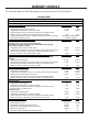
TABLE OF CONTENTS
SECTION 1:SAFETY INSTRUCTIONS AND WARNINGS ................................................ 1-1
1.01 Arc Welding Hazards ....................................................................................... 1-1
1.02 Principal Safety Standards .............................................................................. 1-4
1.03 Symbol Chart .................................................................................................. 1-5
1.04 Precautions De Securite En Soudage A L’arc .................................................. 1-6
1.05 Dangers relatifs au soudage à l’arc ................................................................. 1-6
1.06 Principales Normes De Securite ..................................................................... 1-9
1.07 Graphique de Symbole .................................................................................. 1-10
SECTION 2:INTRODUCTION ............................................................................... 2-1
2.01 How to Use This Manual ................................................................................. 2-1
2.02 Equipment Identification ................................................................................. 2-1
2.03 Receipt of Equipment ...................................................................................... 2-1
2.04 Description ..................................................................................................... 2-1
2.05 Transportation Methods .................................................................................. 2-1
2.06 Duty Cycle ....................................................................................................... 2-1
2.07 Specifications ................................................................................................. 2-2
SECTION 3:INSTALLATION ................................................................................ 3-1
3.01 Environment ................................................................................................... 3-1
3.02 Location .......................................................................................................... 3-1
3.03 Electrical Input Connections ........................................................................... 3-1
3.04 Electromagnetic Compatibility ........................................................................ 3-4
3.05 Setup for Welding ........................................................................................... 3-5
3.06 STICK (SMAW) Setup ..................................................................................... 3-6
3.07 Lift TIG (GTAW) Setup .................................................................................... 3-7
SECTION 4:OPERATION .................................................................................... 4-1
4.01 Front Panel ..................................................................................................... 4-1
4.02 SMAW Electrode Polarity ................................................................................ 4-2
4.03 Effects of Stick Welding Various Materials ...................................................... 4-2
4.04 GTAW Electrode Polarity ................................................................................. 4-3
4.05 Guide for Selecting Filler Wire ........................................................................ 4-3
4.06 Tungsten Electrode Current Ranges ................................................................ 4-3
4.07 Shielding Gas Selection .................................................................................. 4-3
4.08 Tungsten Electrode Types ............................................................................... 4-3
4.09 TIG Welding Parameters for Steel ................................................................... 4-3
4.10 Arc Welding Practice ....................................................................................... 4-4
4.11 Welding Position ............................................................................................. 4-4
4.12 Joint Preparations ........................................................................................... 4-5
4.13 Arc Welding Technique ................................................................................... 4-6
4.14 The Welder ...................................................................................................... 4-6
4.15 Striking the Arc ............................................................................................... 4-6
4.16 Arc Length ...................................................................................................... 4-6
4.17 Rate of Travel .................................................................................................. 4-6
4.18 Making Welded Joints ..................................................................................... 4-6
4.19 Distortion ........................................................................................................ 4-8
4.20 The Cause of Distortion .................................................................................. 4-9
4.21 Overcoming Distortion Effects ........................................................................ 4-9

TABLE OF CONTENTS
SECTION 5:SERVICE ....................................................................................... 5-1
5.01 Maintenance and Inspection ........................................................................... 5-1
5.02 STICK Welding Problems ............................................................................... 5-2
5.03 TIG Welding Problems ................................................................................... 5-3
5.04 Power Source Problems ................................................................................ 5-4
APPENDIX 1: REPLACEMENT PARTS .................................................................... A-1
APPENDIX 2: OPTIONS AND ACCESSORIES ............................................................ A-2
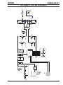
APPENDIX 3: system schematic ......................................................................... A-3
LIMITED WARRANTY
WARRANTY SCHEDULE
GLOBAL CUSTOMER SERVICE CONTACT INFORMATION ................................... Inside Rear
Page is loading ...

SAFETY INSTRUCTIONS THERMAL ARC 95 S
Safety Instructions 1-1 Manual 0-5086
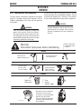
1.01 Arc Welding Hazards
WARNING
ELECTRIC SHOCK can kill.
Touching live electrical parts can cause fatal shocks or
severe burns. The electrode and work circuit is electri-
cally live whenever the output is on. The input power
circuit and machine internal circuits are also live when
power is on. In semi-automatic or automatic wire weld-
ing, the wire, wire reel, drive roll housing, and all metal
parts touching the welding wire are electrically live.
Incorrectly installed or improperly grounded equipment
is a hazard.
1. Do not touch live electrical parts.
2. Wear dry, hole-free insulating gloves and body protection.
3. Insulate yourself from work and ground using dry insulating mats
or covers.
4. Disconnect input power or stop engine before installing or
servicing this equipment. Lock input power disconnect switch
open, or remove line fuses so power cannot be turned on
accidentally.
5. Properly install and ground this equipment according to its Owner’s
Manual and national, state, and local codes.
6. Turn off all equipment when not in use. Disconnect power to
equipment if it will be left unattended or out of service.
7. Use fully insulated electrode holders. Never dip holder in water to
cool it or lay it down on the ground or the work surface. Do not
touch holders connected to two welding machines at the same
time or touch other people with the holder or electrode.
8. Do not use worn, damaged, undersized, or poorly spliced
cables.
9. Do not wrap cables around your body.
10. Ground the workpiece to a good electrical (earth) ground.
11. Do not touch electrode while in contact with the work (ground)
circuit.
12. Use only well-maintained equipment. Repair or replace damaged
parts at once.
13. In confined spaces or damp locations, do not use a welder with AC
output unless it is equipped with a voltage reducer. Use equipment
with DC output.
14. Wear a safety harness to prevent falling if working above floor
level.
15. Keep all panels and covers securely in place.
WARNING
ARC RAYS can burn eyes and skin; NOISE can damage
hearing. Arc rays from the welding process produce
intense heat and strong ultraviolet rays that can burn
eyes and skin. Noise from some processes can damage
hearing.
1. Wear a welding helmet fitted with a proper shade of filter (see
ANSI Z49.1 listed in Safety Standards) to protect your face and
eyes when welding or watching.
2. Wear approved safety glasses. Side shields recommended.
3. Use protective screens or barriers to protect others from flash and
glare; warn others not to watch the arc.
4. Wear protective clothing made from durable, flame-resistant
material (wool and leather) and foot protection.
5. Use approved ear plugs or ear muffs if noise level is high.
SECTION 1:
SAFETY INSTRUCTIONS AND WARNINGS
!
WARNING
PROTECT YOURSELF AND OTHERS FROM POSSIBLE SERIOUS INJURY OR DEATH. KEEP CHILDREN AWAY. PACEMAKER WEARERS KEEP
AWAY UNTIL CONSULTING YOUR DOCTOR. DO NOT LOSE THESE INSTRUCTIONS. READ OPERATING/INSTRUCTION MANUAL BEFORE
INSTALLING, OPERATING OR SERVICING THIS EQUIPMENT.
Welding products and welding processes can cause serious injury or death, or damage to other equipment or property, if the operator does not
strictly observe all safety rules and take precautionary actions.
Safe practices have developed from past experience in the use of welding and cutting. These practices must be learned through study and
training before using this equipment. Some of these practices apply to equipment connected to power lines; other practices apply to engine
driven equipment. Anyone not having extensive training in welding and cutting practices should not attempt to weld.
Safe practices are outlined in the American National Standard Z49.1 entitled: SAFETY IN WELDING AND CUTTING. This publication and other
guides to what you should learn before operating this equipment are listed at the end of these safety precautions. HAVE ALL INSTALLATION,
OPERATION, MAINTENANCE, AND REPAIR WORK PERFORMED ONLY BY QUALIFIED PEOPLE.

THERMAL ARC 95 S SAFETY INSTRUCTIONS
Manual 0-5086 1-2 Safety Instructinos
WARNING
FUMES AND GASES can be hazardous to your health.
Welding produces fumes and gases. Breathing these
fumes and gases can be hazardous to your health.
1. Keep your head out of the fumes. Do not breathe the fumes.
2. If inside, ventilate the area and/or use exhaust at the arc to remove
welding fumes and gases.
3. If ventilation is poor, use an approved air-supplied respirator.
4. Read the Material Safety Data Sheets (MSDSs) and the
manufacturer’s instruction for metals, consumables, coatings,
and cleaners.
5. Work in a confined space only if it is well ventilated, or while
wearing an air-supplied respirator. Shielding gases used for
welding can displace air causing injury or death. Be sure the
breathing air is safe.
6. Do not weld in locations near degreasing, cleaning, or spraying
operations. The heat and rays of the arc can react with vapors to
form highly toxic and irritating gases.
7. Do not weld on coated metals, such as galvanized, lead, or
cadmium plated steel, unless the coating is removed from the weld
area, the area is well ventilated, and if necessary, while wearing
an air-supplied respirator. The coatings and any metals containing
these elements can give off toxic fumes if welded.
WARNING
WELDING can cause fire or explosion.
Sparks and spatter fly off from the welding arc. The flying
sparks and hot metal, weld spatter, hot workpiece, and
hot equipment can cause fires and burns. Accidental
contact of electrode or welding wire to metal objects
can cause sparks, overheating, or fire.
1. Protect yourself and others from flying sparks and hot metal.
2. Do not weld where flying sparks can strike flammable material.
3. Remove all flammables within 35 ft (10.7 m) of the welding arc.
If this is not possible, tightly cover them with approved covers.
4. Be alert that welding sparks and hot materials from welding can
easily go through small cracks and openings to adjacent areas.
5. Watch for fire, and keep a fire extinguisher nearby.
6. Be aware that welding on a ceiling, floor, bulkhead, or partition
can cause fire on the hidden side.
7. Do not weld on closed containers such as tanks or drums.
8. Connect work cable to the work as close to the welding area as
practical to prevent welding current from traveling long, possibly
unknown paths and causing electric shock and fire hazards.
9. Do not use welder to thaw frozen pipes.
10. Remove stick electrode from holder or cut off welding wire at
contact tip when not in use.
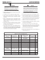
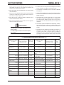
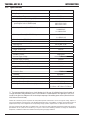
Welding or Cutting
Operation
Electrode Siz
e
Metal Thickness
or Weldin
g
Current
Filter
Shade
No.
Welding or Cutting
Operation
Electrode Siz
e
Metal Thickness
or Weldin
g
Filter
Shade
No.
Torch soldering 2
Gas metal-arc
welding (MIG)
Torch brazing 3 or 4 Non-ferrous base metal All 11
Oxygen Cutting
Non-ferrous base metal All 12
Light Under 1 in., 25 mm 3 or 4 Gas tungsten arc welding All 12
Medium 1 to 6 in., 25-150 mm 4 or 5 (TIG) All 12
Heavy Over 6 in., 150 mm 5 or 6 Atomic hydrogen welding All 12
Gas welding
Carbon arc welding All 12
Light Under 1/8 in., 3 mm 4 or 5 Plasma arc welding
Medium 1/8 to 1/2 in., 3-12 mm 5 or 6
Carbon arc air gouging
Heavy Over 1/2 in., 12 mm 6 or 8 Light 12
Shielded metal-arc
welding
(stick) electrodes
Under 5/32 in., 4 mm 10 Heavy 14
5/32 to 1/4 in.,
4 to 6.4 mm
12
Plasma arc cutting
Over 1/4 in., 6.4 mm 14 Light Under 300 Amp 9
Medium 300 to 400 Amp 12
Heavy Over 400 Amp 14
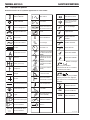
Eye protection filter shade selector for welding or cutting
(goggles or helmet), from AWS A6.2-73.

SAFETY INSTRUCTIONS THERMAL ARC 95 S
Safety Instructions 1-3 Manual 0-5086
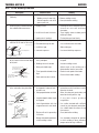
WARNING
FLYING SPARKS AND HOT METAL can cause injury.
Chipping and grinding cause flying metal. As welds cool,
they can throw off slag.
1. Wear approved face shield or safety goggles. Side shields
recommended.
2. Wear proper body protection to protect skin.
WARNING
CYLINDERS can explode if damaged.
Shielding gas cylinders contain gas under high pressure.
If damaged, a cylinder can explode. Since gas cylinders
are normally part of the welding process, be sure to
treat them carefully.
1. Protect compressed gas cylinders from excessive heat, mechanical
shocks, and arcs.
2. Install and secure cylinders in an upright position by chaining
them to a stationary support or equipment cylinder rack to prevent
falling or tipping.
3. Keep cylinders away from any welding or other electrical
circuits.
4. Never allow a welding electrode to touch any cylinder.
5. Use only correct shielding gas cylinders, regulators, hoses, and
fittings designed for the specific application; maintain them and
associated parts in good condition.
6. Turn face away from valve outlet when opening cylinder valve.
7. Keep protective cap in place over valve except when cylinder is in
use or connected for use.
8. Read and follow instructions on compressed gas cylinders,
associated equipment, and CGA publication P-1 listed in Safety
Standards.
!
WARNING
Engines can be dangerous.
WARNING
ENGINE EXHAUST GASES can kill.
Engines produce harmful exhaust gases.
1. Use equipment outside in open, well-ventilated areas.
2. If used in a closed area, vent engine exhaust outside and away
from any building air intakes.
WARNING
ENGINE FUEL can cause fire or explosion.
Engine fuel is highly flammable.
1. Stop engine before checking or adding fuel.
2. Do not add fuel while smoking or if unit is near any sparks or open
flames.
3. Allow engine to cool before fueling. If possible, check and add fuel
to cold engine before beginning job.
4. Do not overfill tank — allow room for fuel to expand.
5. Do not spill fuel. If fuel is spilled, clean up before starting
engine.
WARNING
MOVING PARTS can cause injury.
Moving parts, such as fans, rotors, and belts can cut fingers and hands
and catch loose clothing.
1. Keep all doors, panels, covers, and guards closed and
securely in place.
2. Stop engine before installing or connecting unit.
3. Have only qualified people remove guards or covers for
maintenance and troubleshooting as necessary.
4. To prevent accidental starting during servicing, disconnect
negative (-) battery cable from battery.
5. Keep hands, hair, loose clothing, and tools away from moving
parts.
6. Reinstall panels or guards and close doors when servicing
is finished and before starting engine.
WARNING
SPARKS can cause BATTERY GASES TO EXPLODE;
BATTERY ACID can burn eyes and skin.
Batteries contain acid and generate explosive gases.
1. Always wear a face shield when working on a battery.
2. Stop engine before disconnecting or connecting battery cables.
3. Do not allow tools to cause sparks when working on a battery.
4. Do not use welder to charge batteries or jump start vehicles.
5. Observe correct polarity (+ and –) on batteries.

THERMAL ARC 95 S SAFETY INSTRUCTIONS
Manual 0-5086 1-4 Safety Instructinos
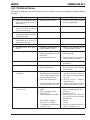
WARNING
STEAM AND PRESSURIZED HOT COOLANT can burn
face, eyes, and skin.
The coolant in the radiator can be very hot and under
pressure.
1. Do not remove radiator cap when engine is hot. Allow engine to
cool.
2. Wear gloves and put a rag over cap area when removing cap.
3. Allow pressure to escape before completely removing cap.
LEAD WARNING
This product contains chemicals, including lead, or
otherwise produces chemicals known to the State of
California to cause cancer, birth defects and other re-
productive harm. Wash hands after handling. (California
Health & Safety Code § 25249.5 et seq.)
NOTE
Considerations About Welding And The Effects of Low
Frequency Electric and Magnetic Fields
The following is a quotation from the General Conclusions Section of
the U.S. Congress, Office of Technology Assessment, Biological Effects
of Power Frequency Electric & Magnetic Fields - Background Paper,
OTA-BP-E-63 (Washington, DC: U.S. Government Printing Office, May
1989): “...there is now a very large volume of scientific findings based
on experiments at the cellular level and from studies with animals
and people which clearly establish that low frequency magnetic fields
interact with, and produce changes in, biological systems. While most
of this work is of very high quality, the results are complex. Current
scientific understanding does not yet allow us to interpret the evidence
in a single coherent framework. Even more frustrating, it does not
yet allow us to draw definite conclusions about questions of possible
risk or to offer clear science-based advice on strategies to minimize
or avoid potential risks.”
To reduce magnetic fields in the workplace, use the following
procedures.
1. Keep cables close together by twisting or taping them.
2. Arrange cables to one side and away from the operator.
3. Do not coil or drape cable around the body.
4. Keep welding power source and cables as far away from body
as practical.
!
ABOUT PACEMAKERS:
The above procedures are among those also normally
recommended for pacemaker wearers. Consult your
doctor for complete information.
1.02 Principal Safety Standards
Safety in Welding and Cutting, ANSI Standard Z49.1, from American
Welding Society, 550 N.W. LeJeune Rd., Miami, FL 33126.
Safety and Health Standards, OSHA 29 CFR 1910, from Superintendent
of Documents, U.S. Government Printing Office, Washington, D.C.
20402.
Recommended Safe Practices for the Preparation for Welding and
Cutting of Containers That Have Held Hazardous Substances, American
Welding Society Standard AWS F4.1, from American Welding Society,
550 N.W. LeJeune Rd., Miami, FL 33126.
National Electrical Code, NFPA Standard 70, from National Fire
Protection Association, Batterymarch Park, Quincy, MA 02269.
Safe Handling of Compressed Gases in Cylinders, CGA Pamphlet P-1,
from Compressed Gas Association, 1235 Jefferson Davis Highway,
Suite 501, Arlington, VA 22202.
Code for Safety in Welding and Cutting, CSA Standard W117.2, from
Canadian Standards Association, Standards Sales, 178 Rexdale
Boulevard, Rexdale, Ontario, Canada M9W 1R3.
Safe Practices for Occupation and Educational Eye and Face Protection,
ANSI Standard Z87.1, from American National Standards Institute,
1430 Broadway, New York, NY 10018.
Cutting and Welding Processes, NFPA Standard 51B, from National Fire
Protection Association, Batterymarch Park, Quincy, MA 02269.

SAFETY INSTRUCTIONS THERMAL ARC 95 S
Safety Instructions 1-5 Manual 0-5086
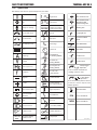
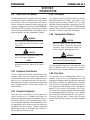
1.03 Symbol Chart
Note that only some of these symbols will appear on your model.
Gas Tungsten Arc
Welding (GTAW)
Air Carbon Arc
Cutting (CAC-A)
Constant Current
Constant Voltage
Or Constant Potential
High Temperature
Fault Indication
Arc Force
Touch Start (GTAW)
Variable Inductance
Voltage Input
Single Phase
Three Phase
Three Phase Static
Frequency Converter-
Transformer-Rectifier
Dangerous Voltage
Off
On
Panel/Local
Shielded Metal
Arc Welding (SMAW)
Gas Metal Arc
Welding (GMAW)
Increase/Decrease
Circuit Breaker
AC Auxiliary Power
Remote
Duty Cycle
Percentage
Amperage
Voltage
Hertz (cycles/sec)
Frequency
Negative
Positive
Direct Current (DC)
Protective Earth
(Ground)
Line
Line Connection
Auxiliary Power
Receptacle Rating-
Auxiliary Power
Art # A-04130
115V 15A
t
t1
t2
%
X
IPM
MPM
t
V
Fuse
Wire Feed Function
Wire Feed Towards
Workpiece With
Output Voltage Off.
Preflow Time
Postflow Time
Spot Time
Spot Weld Mode
Continuous Weld
Mode
Press to initiate wirefeed and
welding, release to stop.
Purging Of Gas
Inches Per Minute
Meters Per Minute
Welding Gun
Burnback Time
Press and hold for preflow, release
to start arc. Press to stop arc, and
hold for preflow.
4 Step Trigger
Operation
2 Step Trigger
Operation
Page is loading ...
Page is loading ...
Page is loading ...

SAFETY INSTRUCTIONS THERMAL ARC 95 S
Safety Instructions 1-9 Manual 0-5086
2. Ne faites pas le plein en fumant ou proche d’une source d’étincelles
ou d’une flamme nue.
3. Si c’est possible, laissez le moteur refroidir avant de faire le plein
de carburant ou d’en vérifier le niveau au début du soudage.
4. Ne faites pas le plein de carburant à ras bord: prévoyez de l’espace
pour son expansion.
5. Faites attention de ne pas renverser de carburant. Nettoyez tout
carburant renversé avant de faire démarrer le moteur.
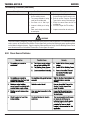
AVERTISSEMENT
DES PIECES EN MOUVEMENT PEUVENT CAUSER DES
BLESSURES.
Des pièces en mouvement, tels des ventilateurs, des
rotors et des courroies peuvent couper doigts et mains,
ou accrocher des vêtements amples.
1. Assurez-vous que les portes, les panneaux, les capots et les
protecteurs soient bien fermés.
2. Avant d’installer ou de connecter un système, arrêtez le moteur.
3. Seules des personnes qualifiées doivent démonter des protecteurs
ou des capots pour faire l’entretien ou le dépannage nécessaire.
4. Pour empêcher un démarrage accidentel pendant l’entretien,
débranchez le câble d’accumulateur à la borne négative.
5. N’approchez pas les mains ou les cheveux de pièces en mouve-
ment; elles peuvent aussi accrocher des vêtements amples et des
outils.
6. Réinstallez les capots ou les protecteurs et fermez les portes après
des travaux d’entretien et avant de faire démarrer le moteur.
AVERTISSEMENT
DES ETINCELLES PEUVENT FAIRE EXPLOSER UN ACCU-
MULATEUR; L’ELECTROLYTE D’UN ACCUMU-LATEUR
PEUT BRULER LA PEAU ET LES YEUX.
Les accumulateurs contiennent de l’électrolyte acide et
dégagent des vapeurs explosives.
1. Portez toujours un écran facial en travaillant sur un accumu-la-
teur.
2. Arrêtez le moteur avant de connecter ou de déconnecter des câbles
d’accumulateur.
3. N’utilisez que des outils anti-étincelles pour travailler sur un ac-
cumulateur.
4. N’utilisez pas une source de courant de soudage pour charger un
accumulateur ou survolter momentanément un véhicule.
5. Utilisez la polarité correcte (+ et –) de l’accumulateur.
AVERTISSEMENT
LA VAPEUR ET LE LIQUIDE DE REFROIDISSEMENT
BRULANT SOUS PRESSION PEUVENT BRULER LA
PEAU ET LES YEUX.
Le liquide de refroidissement d’un radiateur peut être
brûlant et sous pression.
1. N’ôtez pas le bouchon de radiateur tant que le moteur n’est pas
refroidi.
2. Mettez des gants et posez un torchon sur le bouchon pour
l’ôter.
3. Laissez la pression s’échapper avant d’ôter complètement le
bouchon.
PLOMB AVERTISSEMENT
Ce produit contient des produits chimiques, comme
le plomb, ou engendre des produits chimiques,
reconnus par l’état de Californie comme pou-
vant être à l’origine de cancer, de malformations
fœtales ou d’autres problèmes de reproduction.
Il faut se laver les mains après toute manipulation.
(Code de Californie de la sécurité et santé, paragraphe
25249.5 et suivants)
1.06 Principales Normes De Securite
Safety in Welding and Cutting, norme ANSI Z49.1, American Welding
Society, 550 N.W. LeJeune Rd., Miami, FL 33128.
Safety and Health Standards, OSHA 29 CFR 1910, Superintendent
of Documents, U.S. Government Printing Office, Washington, D.C.
20402.
Recommended Safe Practices for the Preparation for Welding and
Cutting of Containers That Have Held Hazardous Substances, norme
AWS F4.1, American Welding Society, 550 N.W. LeJeune Rd., Miami,
FL 33128.
National Electrical Code, norme 70 NFPA, National Fire Protection
Association, Batterymarch Park, Quincy, MA 02269.
Safe Handling of Compressed Gases in Cylinders, document P-1,
Compressed Gas Association, 1235 Jefferson Davis Highway, Suite
501, Arlington, VA 22202.
Code for Safety in Welding and Cutting, norme CSA W117.2 Association
canadienne de normalisation, Standards Sales, 276 Rexdale Boulevard,
Rexdale, Ontario, Canada M9W 1R3.
Safe Practices for Occupation and Educational Eye and Face Protec-
tion, norme ANSI Z87.1, American National Standards Institute, 1430
Broadway, New York, NY 10018.
Cutting and Welding Processes, norme 51B NFPA, National Fire Protec-
tion Association, Batterymarch Park, Quincy, MA 02269.
Page is loading ...

INTRODUCTION THERMAL ARC 95 S
Introduction 2-1 Manual 0-5086
SECTION 2:
INTRODUCTION
2.01 How to Use This Manual
This Operating Manual usually applies to the part numbers
listed on page i. If none are underlined, they are all covered
by this manual. To ensure safe operation, read the entire
manual, including the chapter on safety instructions and
warnings. Throughout this manual, the word WARNING,
CAUTION and NOTE may appear. Pay particular attention
to the information provided under these headings. These
special annotations are easily recognized as follows:
!
WARNING
Gives information regarding possible personal
injury. Warnings will be enclosed in a box
such as this.
CAUTION
Refers to possible equipment damage. Cau-
tions will be shown in bold type.
NOTE
Offers helpful information concerning certain
operating procedures. Notes will be shown
in italics
2.02 Equipment Identification
The unit’s identification number (specification or part
number), model, and serial number usually appear on
a nameplate attached to the machine. Equipment which
does not have a nameplate attached to the machine is
identified only by the specification or part number printed
on the shipping container. Record these numbers for
future reference.
2.03 Receipt of Equipment
When you receive the equipment, check it against the
invoice to make sure it is complete and inspect the
equipment for possible damage due to shipping. If there is
any damage, notify the carrier immediately to file a claim.
Furnish complete information concerning damage claims
or shipping errors to the location in your area listed in the
inside back cover of this manual. Include all equipment
identification numbers as described above along with a
full description of the parts in error.
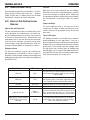
2.04 Description
This compact inverter welding machine has infinitely
adjustable welding current from 5 to 95 amps. It uses
standard general purpose SMAW 3/32” (2.5mm)
electrodes for light gauge work, generally less than 1/8”
(3.2mm) thick. The unit also has a Lift TIG (GTAW) welding
mode that offers stable TIG welding characteristics when
used with a suitable TIG torch and shielding gas.
2.05 Transportation Methods
CAUTION
ELECTRIC SHOCK can kill. DO NOT TOUCH
live electric parts. Disconnect input power
conductors from de-energized supply line
before moving the welding power source.
!
WARNING
FALLING EQUIPMENT can cause serious per-
sonal injury and equipment damage.
Lift unit with handle on top of case. Use handcart or similar
device of adequate capacity. If using a fork lift vehicle,
place secure unit on a proper skid before transporting.
2.06 Duty Cycle
The rated duty cycle of a Welding Power Source, is a
statement of the time it may be operated at its rated
welding current output without exceeding the temperature
limits of the insulation of the component parts. To explain
the 10 minute duty cycle period the following example is
used. Suppose a Welding Power Source is designed to
operate at a 30% duty cycle, 80 amperes at 23.2 volts.
This means that it has been designed and built to provide
the rated amperage (80A) for 3 minutes, i.e. arc welding
time, out of every 10 minute period (30% of 10 minutes is
3 minutes). During the other 7 minutes of the 10 minute
period the Welding Power Source must idle and allowed
to cool.

THERMAL ARC 95 S INTRODUCTION
Manual 0-5086 2-2 Introduction
2.07 Specifi cations
Power Source Part Number W1003200
Welding Output
Welding Current Range 5 - 95 Amps
Nominal DC Open Circuit Voltage (OCV) 60V
Welding Output, 104º F (40º C), 10 min.
(quoted fi gures refer to SMAW output)
50A / 22V @ 100%
80A / 23.2V @ 30%
90A / 23.6V @ 20%
Rated Input Current (A) for STICK Welding 33.5A
Iο = 90A @ 23.6V
Rated Input Current (A) for TIG Welding 21.0A
Io = [email protected]
Rated Output for STICK Welding 90A / 23.6V @ 20%
Rated Output for TIG Welding 95A / 13.8V @ 20%
Duty Cycle (%) 20% @ 90A / 23.6V
Welder Type Inverter Power Source
Output Terminal Type Dinse 25
Mains Power
Number of Phases Single Phase
Nominal Supply Voltage 115V
Nominal Supply Frequency 50/60 Hz
Effective Input Current (l1eff) 15.0 Amps
Maximum Input Current (l1 max) Δ 33.5 Amps
Single Phase Generator Requirements 6 KVA
Classifi cation
Protection Class IP23S
Standards IEC 60974-1
Cooling Method Fan Cooled
Dimensions and Weight
Welding Power Source Mass 9.7 lb. (4.4 kg)
Welding Power Source Dimensions (Height x Width x Depth) H 13.0" x W 5.1" x D 9.0"
(H 330mm x W 130mm x D 230mm)
Δ The recommended time delay fuse or circuit breaker size is 30 amp. An individual branch circuit capable of
carrying 30 amperes and protected by fuses or circuit breaker is recommended for this application. Fuse size is
based on not more than 200 percent of the rated input amperage of the welding power source (Based on Article
630, National Electrical Code).
Thermal Arc continuously strives to produce the best product possible and therefore reserves the right to change, improve or
revise the specifi cations or design of this or any product without prior notice. Such updates or changes do not entitle the buyer of
equipment previously sold or shipped to the corresponding changes, updates, improvements or replacement of such items.
The values specifi ed in the table above are optimal values, your values may differ. Individual equipment may differ from the above
specifi cations due to in part, but not exclusively, to any one or more of the following; variations or changes in manufactured
components, installation location and conditions and local power grid supply conditions.

INSTALLATION THERMAL ARC 95 S
Installation 3-1 Manual 0-5086
3.01 Environment
These units are designed for use in environments
with increased hazard of electric shock. Examples of
environments with increased hazard of electric shock
are:
A. In locations in which freedom of movement is
restricted, so that the operator is forced to perform the
work in a cramped (kneeling, sitting or lying) position
with physical contact with conductive parts.
B. In locations which are fully or partially limited by
conductive elements, and in which there is a high risk
of unavoidable or accidental contact by the operator.
C. In wet or damp hot locations where humidity or
perspiration considerably reduces the skin resistance
of the human body and the insulation properties of
accessories.
Environments with increased hazard of electric shock do
not include places where electrically conductive parts in
the near vicinity of the operator, which can cause increased
hazard, have been insulated.
3.02 Location
Be sure to locate the welder according to the following
guidelines:
• In areas, free from moisture and dust.
• Ambient temperature between 32°F (0°C) to 104° F
(40° C).
• In areas, free from oil, steam and corrosive gases.
• In areas, not subjected to abnormal vibration or
shock.
• In areas, not exposed to direct sunlight or rain.
• Place at a distance of 12” (300mm) or more from
walls or similar that could restrict natural air flow
for cooling
!
WARNING
Thermal Arc advises that this equipment
be electrically connected by a qualified
electrician.
SECTION 3:
INSTALLATION
3.03 Electrical Input Connections
!
WARNING
ELECTRIC SHOCK can kill; SIGNIFICANT DC
VOLTAGE is present after removal of input
power.
DO NOT TOUCH live electrical parts.
SHUT DOWN welding power source, disconnect input
power employing lockout/tagging procedures. Lock-out/
tagging procedures consist of padlocking line disconnect
switch in open position, removing fuses from fuse box,
or shutting off and red-tagging circuit breaker or other
disconnecting device.
• Electrical Input Requirements
Operate the welding power source from a single-phase
50/60 Hz, AC power supply. The input voltage must match
one of the electrical input voltages shown on the input
data label on the unit nameplate. Contact the local electric
utility for information about the type of electrical service
available, how proper connections should be made, and
inspection required. The line disconnect switch provides
a safe and convenient means to completely remove all
electrical power from the welding power supply whenever
necessary to inspect or service the unit.
Do not connect an input (WHITE or BLACK) conductor to
the ground terminal.

THERMAL ARC 95 S INSTALLATION
Manual 0-5086 3-2 Installation
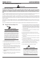
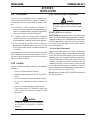
Refer to Figure 3-1:
1. Connect end of ground (GREEN or GREEN/YELLOW) conductor to a suitable ground. Use a grounding method
that complies with all applicable electrical codes.
2. Connect ends of line 1 (BLACK) and line 2 (WHITE) input conductors to a de-energized line disconnect switch.
3. Use Table 3-1 as a guide to select line fuses for the disconnect switch.
Input Voltage Fuse Size
115V 30 Amps
Figure 3-1: Electrical Input Connections
CAUTION
The time-delay fuses or circuit breaker of an individual branch circuit may have nuisance tripping when
welding with this product due to the amperage rating of the time-delay fuses or circuit breaker.
The recommended time-delay fuses or circuit breaker size is 30 amperes. Fuse/circuit breaker size is based
on not more than 200 percent of the rated input amperage of the welding power source (Based on Article
630, National Electrical Code).
An individual branch circuit capable of carrying 30 amperes and time-delay fuses or circuit breaker protec-
tion is recommended for this application.
Art #: A-08473_AB
Welding Power Supply
Primary Power Cable
120 V, 20A, 1Ø

INSTALLATION THERMAL ARC 95 S
Installation 3-3 Manual 0-5086
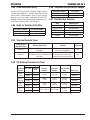
Input Power
Each unit incorporates an INRUSH circuit. When the MAIN CIRCUIT SWITCH is turned on, the inrush circuit provides
pre-charging for the input capacitors. A relay in the Power Control Assembly (PCA) will turn on after the input capacitors
have charged to operating voltage (after approximately 5 seconds)
NOTE
Damage to the PCA could occur if 133 VAC or higher is applied to the Primary Power Cable.
Table 3-2: Primary Circuit Sizes to Achieve Maximum Current
Model
Primary Supply Lead Size
(Factory Fitted)
Minimum Primary
Current Circuit Size
(Vin/Amps)
Current & Duty Cycle
TIG STICK
Thermal Arc 95 S 12 AWG (3.3mm²)
115V/30A - 90A / 23.6V @ 20%
115V/21A 95A / 13.8V @ 20% -

THERMAL ARC 95 S INSTALLATION
Manual 0-5086 3-4 Installation
3.04 Electromagnetic Compatibility
!
WARNING
Extra precautions for Electromagnetic
Compatibility may be required when this
Welding Power Source is used in a domestic
situation.
A. Installation and Use - Users Responsibility
The user is responsible for installing and using the welding
equipment according to the manufacturer’s instructions.
If electromagnetic disturbances are detected then it shall
be the responsibility of the user of the welding equipment
to resolve the situation with the technical assistance of
the manufacturer. In some cases this remedial action
may be as simple as earthing the welding circuit, see
NOTE below. In other cases it could involve constructing
an electromagnetic screen enclosing the Welding Power
Source and the work, complete with associated input
filters. In all cases, electromagnetic disturbances shall be
reduced to the point where they are no longer Trouble-
some.
B. Assessment of Area
Before installing welding equipment, the user shall make
an assessment of potential electromagnetic problems in
the surrounding area. The following shall be taken into
account.
1. Other supply cables, control cables, signaling and
telephone cables; above, below and adjacent to the
welding equipment.
2. Radio and television transmitters and receivers.
3. Computer and other control equipment.
4. Safety critical equipment, e.g. guarding of industrial
equipment.
5. The health of people around, e.g. the use of pace-
makers and hearing aids.
6. Equipment used for calibration and measurement.
7. The time of day that welding or other activities are to
be carried out.
8. The immunity of other equipment in the environment:
the user shall ensure that other equipment being used
in the environment is compatible: this may require
additional protection measures.
The size of the surrounding area to be considered will
depend on the structure of the building and other activities
that are taking place. The surrounding area may extend
beyond the boundaries of the premises.
C. Methods of Reducing Electromagnetic Emissions
1. Mains Supply
Welding equipment should be connected to the
mains supply according to the manufacturer’s
recommendations. If interference occurs, it may be
necessary to take additional precautions such as
filtering of the mains supply. Consideration should
be given to shielding the supply cable of permanently
installed welding equipment in metallic conduit or
equivalent. Shielding should be electrically continuous
throughout its length. The shielding should be
connected to the Welding Power Source so that good
electrical contact is maintained between the conduit
and the Welding Power Source enclosure.
2. Maintenance of Welding Equipment
The welding equipment should be routinely maintained
according to the manufacturer’s recommendations. All
access and service doors and covers should be closed
and properly fastened when the welding equipment
is in operation. The welding equipment should not
be modified in any way except for those changes
and adjustments covered in the manufacturer’s
instructions. In particular, the spark gaps of arc
striking and stabilizing devices should be adjusted
and maintained according to the manufacturer’s
recommendation
3. Welding Cables
The welding cables should be kept as short as possible
and should be positioned close together, running at or
close to the floor level.
4. Equipotential Bonding
Bonding of all metallic components in the welding
installation and adjacent to it should be considered.
However, metallic components bonded to the work
piece will increase the risk that the operator could
receive a shock by touching the metallic components
and the electrode at the same time. The operator
should be insulated from all such bonded metallic
components.

INSTALLATION THERMAL ARC 95 S
Installation 3-5 Manual 0-5086
5. Earthing of the Work Piece
Where the work piece is not bonded to earth for electri-
cal safety, nor connected to earth because of its size
and position, e.g. ship’s hull or building steelwork,
a connection bonding the work piece to earth may
reduce emissions in some, but not all instances. Care
should be taken to prevent the earthing of the work
piece increasing the risk of injury to users, or damage
to other electrical equipment. Where necessary, the
connection of the work piece to earth should be made
by direct connection to the work piece, but in some
countries where direct connection is not permitted, the
bonding should be achieved by suitable capacitance,
selected according to national regulations.
6. Screening and Shielding
Selective screening and shielding of other cables
and equipment in the surrounding area may alleviate
problems of interference. Screening the entire
welding installation may be considered for special
applications.
3.05 Setup for Welding
NOTE
Conventional operating procedures apply
when using the Welding Power Source, i.e.
connect work lead directly to work piece and
electrode lead is used to hold electrode. Wide
safety margins provided by the design ensure
that the Welding Power Source will withstand
short-term overload without adverse effects.
The welding current range values should be
used as a guide only. Current delivered to the
arc is dependent on the welding arc voltage,
and as welding arc voltage varies between
different classes of electrodes, welding cur-
rent at any one setting would vary according
to the type of electrode in use. The operator
should use the welding current range values
as a guide then fine tune the welding current
to suit the application.
!
WARNING
Before connecting the work clamp to the work
and inserting the electrode in the electrode
holder make sure the Primary power supply
is switched off.

THERMAL ARC 95 S INSTALLATION
Manual 0-5086 3-6 Installation
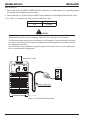
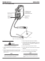
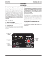
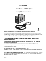
Figure 3-2: Setup for STICK Welding
Stick Mode Sequence of Operation
CAUTION
Before any welding is to begin, be sure to wear all ap-
propriate and recommended safety equipment.
1. Switch the ON/OFF Switch (located on the rear panel)
to OFF.
2. Connect the ground clamp cable to the negative output
terminal, and the electrode holder cable to the positive
output terminal.
NOTE
This set up is known as DC Electrode Positive or reverse
polarity. Please consult with the stick electrode manu-
facturer for specific polarity recommendations.
3.06 STICK (SMAW) Setup
3. Connect the ground clamp to your workpiece.
4. Plug the power cable into the appropriate outlet, and
turn the switch to the “ON” position. The power L.E.D
light should illuminate.
5. Set the “Process Selection Switch” to Stick
6. Set the weld current control knob to the desired
amperage.
7. Install a stick electrode in the electrode holder.
8. You are now ready to begin Stick Welding
NOTE
Gently strike the electrode on the work piece to gener-
ate a welding arc, and slowly move along the work
piece while holding a consistent arc length above base
metal.
200A
Set Welding Current
as specified by the
Electrode Manufacturer.
Set Process Selection
Switch to Stick.
Positive Output
Terminal
(Dinse™ 25)
Negative Output
Terminal
(Dinse™ 25)
Art #: A-08602

INSTALLATION THERMAL ARC 95 S
Installation 3-7 Manual 0-5086
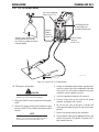
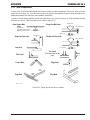
3.07 Lift TIG (GTAW) Setup
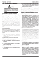
Figure 3-3: Setup for Lift TIG (GTAW) Welding
Lift TIG Sequence of Operation
CAUTION
Before any welding is to begin, be sure to wear all ap-
propriate and recommended safety equipment.
1. Switch the ON/OFF Switch (located on the rear panel)
to OFF.
2. Connect the ground clamp cable to positive output
terminal, and the TIG torch cable to the negative output
terminal.
NOTE
This set up is known as Straight Polarity or DC Electrode
Negative. This is commonly used for DC TIG welding on
most materials such as steel and stainless steel.
3. Using a secured Argon cylinder, slowly crack open then
close the cylinder valve while standing off to the side
of the valve. This will remove any debris that may be
around the valve & regulator seat area.
4. Install the regulator and tighten with a wrench.
5. Connect the gas hose to the outlet of the Argon
regulator, and tighten with a wrench.
6. Be sure the gas valve on the torch is closed, and
slowly open the Argon Cylinder Valve to the fully open
position.
7. Connect the ground clamp to your work piece.
8. Plug the power cable into the appropriate outlet, and
turn the switch to the “ON” position. The power L.E.D.
light should illuminate.
Set Process Selection
Switch to LIFT TIG.
Positive Output
Terminal
(Dinse™ 25)
Negative
Output
Terminal
(Dinse™ 25)
Art #: A-08603
Set Welding Current
as specified by the
Electrode Manufacturer.
Secure the gas cylinder in an
upright position by chaining it
to a stationary support to prevent
falling or tipping.
Page is loading ...
Page is loading ...
Page is loading ...
Page is loading ...
Page is loading ...
Page is loading ...
Page is loading ...
Page is loading ...
Page is loading ...
Page is loading ...
Page is loading ...
Page is loading ...
Page is loading ...
Page is loading ...
Page is loading ...
Page is loading ...
Page is loading ...
Page is loading ...
Page is loading ...
Page is loading ...
Page is loading ...
Page is loading ...
Page is loading ...
-
 1
1
-
 2
2
-
 3
3
-
 4
4
-
 5
5
-
 6
6
-
 7
7
-
 8
8
-
 9
9
-
 10
10
-
 11
11
-
 12
12
-
 13
13
-
 14
14
-
 15
15
-
 16
16
-
 17
17
-
 18
18
-
 19
19
-
 20
20
-
 21
21
-
 22
22
-
 23
23
-
 24
24
-
 25
25
-
 26
26
-
 27
27
-
 28
28
-
 29
29
-
 30
30
-
 31
31
-
 32
32
-
 33
33
-
 34
34
-
 35
35
-
 36
36
-
 37
37
-
 38
38
-
 39
39
-
 40
40
-
 41
41
-
 42
42
-
 43
43
-
 44
44
-
 45
45
-
 46
46
-
 47
47
-
 48
48


ESAB 95 S THERMAL ARC® Inverter Arc Welder User manual
- Category
- Welding System
- Type
- User manual
- This manual is also suitable for
Ask a question and I''ll find the answer in the document
Finding information in a document is now easier with AI
Related papers
-
ESAB 251 FABRICATOR® Mig Welding Machine User manual
-
-
-
-
-
-
ESAB 95 S THERMAL ARC® Inverter Arc Welder User manual
-
-
ESAB A 2000 ULTRAFEED® Variac Controlled Wire Feeder User manual
-
Other documents
-
 HIT Welding 802030 User guide
-
 HIT Welding 802030 User guide
-
 METAL MAN I80 User manual
-
 HIT Welding 802030 User manual
-
 Thermal Arc 211i Operating instructions
-
Ross RXT150E General Instructions Manual
-
 Thermal Comfort 3000 User manual
-
 Thermal Arc PORTAFEED VS 212 Operating instructions
-
HobartWelders HELMET INVENTOR AUTO-DARKENING Owner's manual
-
Miller DIGITAL INFINITY SERIES AUTO-DARKENING HELMETS CL2 Owner's manual


