Page is loading ...


SERVICE MANUAL
Standard - Morgana FRN-6 and SRN-9x
Read this manual, and thoroughly
familiarize yourself with its
contents before operating or
servicing this equipment.


ROTARY
PAGE 2
SERVICE
i .......... Introduction
The purpose of this Manual is to explain the procedure for dis-
mantling and re-assembly of the major assemblies on both the
Friction-Feed and Suction Feed Rotary Numbering Machines.
All the engineering adjustments are shown at the end of each
relevant section.
Operator's adjustments and routine maintenance are explained in
the appropriate Operators Guide which should always be used in
conjunction with this manual.
It is always a good idea to have a copy of the machines Illustrated
Parts Manual available when servicing, as its illustrations provide
an invaluable reference to the construction of the individual
assemblies used to build the machine.
ii ......... Fasteners
Most of the pulleys on the machines use dog-point screws, which
engage in holes in the shafts to ensure reliable drive. They must be
fully withdrawn prior to dismantling.
All threaded fasteners are ISO-Metric & all nuts are ISO-Metric
Hexagon. All screws are hardened high tensile steel.
SERVICE MANUAL
INTRODUCTION
ROTARY NUMBERING MACHINES

NUMBERER
PAGE 3
MANUAL
INTRODUCTION
Cap Head, Button Head, Socket Countersunk, Shoulder Bolts and
Grub-Screws have internal hexagon drives which require ISO-
Metric Hexagon Wrenches (Allen Keys). Ball Drivers may be used,
but care should be taken -particularly when releasing screws for
dismantling- to avoid breaking the driver as they cannot cope with
full tightening torques.
NOTE...... Do not substitute fasteners with low grade alternatives
which may fail or become irremovable.
Pan Head and Cross-Head Countersunk Screws all have ISO-Metric
Taptite Threads and Pozi-Drive Recesses. Use No.2 Point Pozidriv
or Supadriv Drivers for all screws M4 & above, and No.1 Point
Drivers for M3 & below.
WARNING
DO NOT USE PHILLIPS DRIVERS - THESE WILL DAMAGE
THE SCREWS & MAY SLIP, CAUSING DAMAGE OR
INJURY.
iii ........ Identification
For general identification of areas of the machines, the following
terms are used:-
Operator Side
Clutch Side (opposite Operator Side)
Feeder End ( on your Left )
Delivery End ( on your Right )

ROTARY
PAGE 4
SERVICE
INDEX
Introduction ..... .................................................Page 2
¡ Introduction 2
¡¡ Fasteners 2
¡¡¡ Identification 3
Section ..1 .......Covers ......................................Page 6
1.1 Side Covers - Friction Machine 6
1.2 Covers - Suction Machine 7
Section ..2 .......Friction Feed.............................Page 8
2.1 Friction Feed Drive Shaft 8
2.2 Drive Shaft Adjustment 9
2.3 Feed Clutch 10
Section ..3 .......Suction Feed...........................Page 11
3.1 Vacuum Roller 11
3.2 Vacuum Roller Adjustment 12
3.3 Vacuum Hose 14
3.4 Vacuum Belt Adjustment 15
Section ..4 .......Drive Belts..............................Page 16
4.1 Twin Grip Drive Belt 16
4.2 Adjustment - Twin Grip Belt 17
4.3 Motor Drive Belt - Adjustment 17
Section ..5 .......Input Rollers ...........................Page 18
5.1 Input Rollers - Removal 18
Section ..6 .......Output Shafts..........................Page 20
6.1 Output Shaft - Removal 20
Section ..7 .......Inking......................................Page 22
7.1 Ink Transfer Rollers & Shaft - Removal 22
7.2 Ink Transfer Roller - Pressure Adjustment 23
Section ..8 .......Registration ............................Page 24
8.1 Numbering Registration 24
8.2 Operational Problems 24
8.3 Machine Problems 24
8.4 Clutch Problems 25
Section ..9 .......Clutch Assembly .....................Page 26
9.1 Clutch Assembly - Removal 26
9.2 Over-travel - Measurement 27
9.3A Over-travel - Adjustment (Old Style Clutch) 28
9.3B Over-travel - Adjustment (New Style Clutch) 30

NUMBERER
PAGE 5
MANUAL
INDEX
9.4 Actuator - Measurement 32
9.5 Actuator - Adjustment 33
9.6 Collar Position - Measurement 33
9.7 Collar Position - Adjustment 34
9.8 Clutch Position Switch 35
Section ..10 .....Main Print Shaft ......................Page 36
10.1 Main Print Shaft - Removal 36
10.2 Main Print Shaft - Re-assembly 37
Section ..11 .....Platen .....................................Page 38
11.1 Platen Removal 38
11.2 Platen Re-assembly 39
11.3 Platen Adjustment 40
Section ..12 .....Sensor....................................Page 42
12.1 Sensor - All Machines 42
12.2 Sensor Replacement 43
Section ..13 .....Guards....................................Page 44
13.1 Guard Position 44
13.2 Strippers 45
Section ..14 .....Compressor............................Page 46
14.1 Compressor - Suction Machine 46
14.3 Filters 47
14.4 Compressor Removal 47
Section ..15 .....Suction Control Valve..............Page 48
15.1 Suction Control Valve 48
15.2 Valve - Dismantling 49
Section ..16 .....Control System - Friction.........Page 50
16.1 Control System - Access 51
16.2 Troubleshooting - Machine Won’t Run 52
16.3 Troubleshooting - Machine Won’t Feed 52
16.4 Troubleshooting - Machine Won’t Number 53
Section ..17 .....Control System - Suction.........Page 54
17.1 Control Box 55
17.2 Control System - Access 57
17.3 Suction Control Board 57
17.4 Motor Speed Control Board 58
17.5 Troubleshooting - Machine Won’t Run 59
17.6 Troubleshooting - Machine Won’t Feed 61
17.7 Troubleshooting - Machine Won’t Number 62

ROTARY
PAGE 6
SERVICE
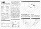
Side Covers - Friction Machine.................................... Fig 1.11
Section 1
SIDE COVERS
1.1 ...... Friction Machine
Each of the side covers is secured by two screws and two nuts as
shown in Fig.1.11. Before removing the clutch cover, remove the
handwheel, using a 10mm socket wrench.
After releasing the operator side cover, but before removing it
completely, you will need to dis-connect the 6 way Trident plug
(which connects the switches on the facia plate to the control
system) from it’s socket on the side frame under the cover.
Note........Do not allow dirt to enter the handwheel bore as it
contains a one-way clutch which operates directly on the
shaft.
Two M6 Nuts
Each Side
Two M4 Screws Each Side M6 Nut & Washer Handwheel
Operator Side Cover Clutch Side Cover
Facia Plate

NUMBERER
PAGE 7
MANUAL
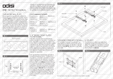
Covers - Suction Machine............................................Fig 1.21
Section 1
COVERS
1.2 ...... Suction Machine
Each side cover is secured by five screws and two nuts as shown
in Fig.1.21. Before removing the clutch side cover, remove the
handwheel, using a 10mm socket wrench.
Note ....... Do not allow dirt to enter the handwheel bore as it
contains a one-way clutch which operates directly on the
shaft.
The base access panel is removed by releasing the four screws,
(two through each side frame) pulling the panel out and then
upwards. Take care not to pull the fan lead which may be easily
unplugged from the control box, inside the machine. (See section
17 on page 53)
M6 Nut & Washer
Hand Wheel
Two M6 Nuts Each Side
Five M4 Screws
Each Side
Base Access
Panel Screws -
Two Each Side

ROTARY
PAGE 8
SERVICE
Friction Feed.............................................................. Fig 2.11
Two Cap Head Bolts Each Side
Grub Screw
Gears Inside Housing Pull Housings Together To Release Pins
Section 2
FRICTION FEED
2.1 ...... Friction Feed Drive Shaft
The friction feed drive shaft is removed after unscrewing the four
cap head bolts as shown in Fig. 2.11. The bearing housings are
located on dowel pins and must be pulled inwards as shown to
release them but take care not to lose the idler gear and washer
from inside the clutch side housing.
To replace the friction feed tyre, the friction feed shaft is
dismantled as follows:- (See Fig. 2.21)
-Remove the grub screw from the drive hub and rotate the drive
hub to align the holes in both hub & shaft so that a 2.5mm hexagon
wrench / allen key will pass through both. This will enable you to
hold the shaft whilst releasing the M6 nut at the end, (using a
10mm socket wrench) and withdraw all components from the
shaft.
Note:.......During dismantling and certainly before re-assembly,
ensure that all components are kept clean and handled
carefully to avoid damage. The drive has to be sensitive
to all stocks - particularly lightweight NCR -& it's
sensitivity will be impaired if the components are

NUMBERER
PAGE 9
MANUAL
Section 2
FRICTION FEED
contaminated or damaged.
2.2 ...... Drive Shaft Adjustment
Re-assemble the shaft in reverse order but set the position of the
drive hub only after the assembly has been fitted into the machine
and the four cap head bolts fully tightened. (See Fig. 2.11).
It is important that the drive hub is positioned laterally on the shaft
so that the support tube has 0.2mm or 0.008" of sideways
Drive Shaft .................................................................Fig 2.21
movement (end float) so tighten the grub screw so that it is radially
well clear of the hole in the shaft.
Note ....... If the grub screw is positioned too close to the hole in the
shaft, it may be impossible to achieve the correct amount
of clearance for the support tube.
Note ....... Take care to make sure the one-way clutch within the
friction tyre operates in the correct direction, & waved
washers have been replaced in their correct positions.
0,2mm / 0.008” End Float Grub Screw
Drive Hub
M6 Nut Waved Washers
Idler Gear
Support Tube
Holes Through Hub & Shaft
Cover Tube
Friction Tyre & Clutch Assembly
Location Dowel Pin

ROTARY
PAGE 10
SERVICE
Note........It’s worth consulting the relevant section in the
appropriate illustrated parts manual to ensure that this
assembly is correctly re-constructed.
2.3 ...... Feed Clutch
The feed clutch is removed from the machine by unplugging it's
wires (taking care not to strain them), and using a 5mm allen key to
unscrew the clutch spindle assembly. (Hold the input roller using a
13mm spanner/wrench on the flats while releasing the spindle).
Upon re-assembly, ensure that the tang on the clutch back-plate
engages with the anchor pin, the drive dog on the sleeve gear
Feed Clutch................................................................ Fig 2.31
13mm A/F Spanner/Wrench
Upper
Input Roller
Clutch Spindle
Assembly
Feed Clutch
Drive Pin
Drive Slots
(input)
Anchor Pin
Flats
Tang Side Frame
(Clutch Side)
Integral Flying Lead
Clutch Cable (to control system)
In-Line Connectors
Un-Plug
Drive Dog
Sleeve Gear Assembly
Drive Slots (Output)
Section 2
FRICTION FEED

NUMBERER
PAGE 11
MANUAL
Section 3
SUCTION FEED
3.1 ...... Vacuum Roller Assembly (See Fig. 3.11 Overleaf)
The vacuum roller is mounted on the bed stiffener beneath the
loading table. To replace the vacuum roller, the loading table,
manifolds, and papergate must be removed.(See Fig 3.11)
-Remove the side-covers and the base access panel. (See
fig.1.21 )
-Remove the two M8 bolts (item 1) which secure the papergate
shaft-and disconnect the hoses from the manifold elbows.
-Remove the four M6 Hex Head screws (item 2) which secure each
manifold mounting bracket to it’s mounting link.
-Remove the hose support beam, by releasing it's two fixing screws
(item 3) and the three nuts (item 4) below the loading table.
-Remove the two M4 nuts (item 5), which secure the underside of
the loading table to the bed stiffener.
-Remove the six M8 bolts (item 6) which secure the loading table to
the side frames and lift the loading table, manifolds and
papergate off the machine as one unit.
-Remove the feed drive timing belt by winding it carefully off the
larger of the two timing pulleys.
-Remove the five screws (item 7) from the bed stiffener (three on
operator side & two on the clutch side), and the two screws (item
8) from the feed bed.
-Cut all cable ties (taking care not to damage the cables) and lift
the vacuum roller assembly and feed bed from the machine.
-Remove the vacuum roller from the subframe by removing the
hose & connecting tube and then releasing the 4 screws holding
the two roller support blocks (See fig.3.31 on page 14)
Replacing the assembly is a reversal of the above but care should
be taken to align all fixing holes BEFORE attempting to replace the
fasteners as damage to the threads will result from mis-aligned
components.

ROTARY
PAGE 12
SERVICE
3.2 ...... Vacuum Roller Adjustment
If the vacuum roller is not set parallel to the input rollers, paper will
always be driven to one side whilst it is feeding.
In order to identify this problem use the following procedure :-
Vacuum Roller Assembly............................................ Fig 3,11
Section 3
SUCTION FEED
Clutch Side Manifold
Operator Side
Manifold
Vacuum
Roller
Feed Drive Timing Belt
Bed
Stiffener
Loading Table
Paper-Gate Shaft
1
Hose
Elbow
Hose Support Beam
2
4
5
6
Paper-Gate
Large Timing Pulley
Feed Drive Shaft
7
8
Feed Bed
Slot
3
Manifold
Mounting
Bracket
Mounting
Link
6

NUMBERER
PAGE 13
MANUAL
-The op side manifold must be set accurately by measuring it's
position on the loading table. (Do not rely on the printed scales
because they may not be accurate enough due to limitations of
the printing process).
-Load some paper and set the clutch side manifold so that there is
no side-ways movement of the paper.
-Run a few sheets with the numbering 'ON', and watch carefully
the edge of the sheet whilst it is feeding.
The edge should always run straight as this indicates that the
vacuum roller is correctly adjusted.
If the edge runs off to one side while the suction is on, and then
runs straight whilst the suction is off (listen to the sound of the
suction while watching the edge of the sheets), the vacuum roller
will require adjusting.
The vacuum roller assembly is set at the factory with it's
adjustment as far forward as possible (to the delivery end of the
machine).
This means that if the sheet edge runs towards the operator side,
the clutch side of the vacuum roller assembly must be adjusted
rearwards (towards the feeder end).
Conversely, if the sheet runs away from the operator side, the
operator side of the vacuum roller assembly must be adjusted
rearwards (towards the feeder end).
The vacuum roller assembly is adjusted by re-positioning the
screws (item 7) in the slots in the side-frames. The M4 nuts (item
5) under the loading table will also have to be released before
adjusting the vacuum roller assembly. (Ensure they are re-
tightened after adjustment is completed).
The feed drive timing belt may also require adjustment (See
section 3.4).
Note ....... Don’t attempt to stretch the drive belt over pulley
flanges.
Section 3
SUCTION FEED

ROTARY
PAGE 14
SERVICE
Section 3
SUCTION FEED
3.3 ...... Vacuum Hose
To disconnect the vacuum hose, remove the grub screw as shown
in Fig.3.31 and slide the connecting tube over the hose. The hose
is then twisted off the vacuum roller spigot.
After replacing the hose & connecting tube the grub screw in the
tube MUST be locked-up so that the suction choke control knob is
in vertical alignment with the suction slot (inside the vacuum
roller).
To achieve this, an alignment tool (a piece of ¼” dia. (Ø6,35mm)
bar at least 2” / 50mm long will do) may be carefully inserted
through one of the holes in the vacuum roller and into the suction
slot.
The suction choke control knob may now be temporarily screwed
into it’s tapped hole in the connecting tube and brought into
vertical alignment with the alignment tool in the vacuum roller
before finally locking the grub screw tight.
Vacuum Hose............................................................. Fig 3.31
Grub Screw
Vacuum Hose
Suction Choke Control
Connecting Tube
Suction Slot ( Inside Vacuum Roller )
Bearing Blocks
Drive Shaft
Vacuum Roller Spigot
Bed Stiffener (Sub Frame)
Alignment Tool
Tapped Hole

NUMBERER
PAGE 15
MANUAL
Section 3
SUCTION FEED
Note ....... Remove the tool and the knob before continuing
assembly
3.4 ...... Vacuum Belt Adjustment
The vacuum drive belt takes the drive from the lower input roller to
the feed drive shaft and is tensioned by adjusting the bearing
blocks.
Release the two screws in each bearing block and move the
screws in their slots until the belt is tensioned.
Care must be taken to ensure that the vacuum drive shaft remains
parallel to the input shafts. (When the feed drive shaft is parallel,
all the adjusting screws will be in similar positions in their slots.)
Failure to set the feed drive shaft correctly will result in the toothed
belt tracking badly and may result in premature belt failure.
WARNING
DO NOT ADJUST THE BELT BY MOVING THE BED
STIFFENER AS THE RESULTING MISALIGNMENT WILL
CAUSE FEEDING PROBLEMS.
Vacuum Belt Adjustment.............................................Fig 3.41
Input Shaft & Vacuum Drive Shafts Must Be Parallel
Bearing Blocks Are Adjustable
Bed Stiffener

ROTARY
PAGE 16
SERVICE
Section 4
DRIVE BELTS
Twin - Grip Drive Belt.................................................. Fig 4.11
4.1 Twin Grip Drive Belt
Remove the operator side cover to gain access to this belt which is
removed only after taking out the bearing housing bolts. This
allows the bearing housing more travel to give extra slack on the
belt which may then be wound off the pulleys in the direction
shown. (See fig.4.11).
When replacing the belt, wind it back on to the pulleys in the same
direction, being careful not to strain the belt.
WARNING
DO NOT ATTEMPT TO REMOVE OR REPLACE THE BELT
WITHOUT FIRST REMOVING THE BOLTS.
Remove Bolts Completely
Before Attempting to
Remove Belt
Belt Direction
Bearing Housing

NUMBERER
PAGE 17
MANUAL
These belts are tensioned by adjusting
the bearing housings after slackening
their fixing bolts. (see note below)
The fixing bolt nearest to the feeder
end of the machine acts as a pivot
whilst the delivery end bolt runs in a
slot in the side frame and allows
adjustment to be made.
The belts should not be over
tensioned, but note that an under
tensioned belt will cause poor
Section 4
DRIVE BELTS
Motor Drive Belt..........................................................Fig 4.31
Motor Drive Belt
Adjust Motor to Tension Belt
Motor Fixing Bolts
4.2 ...... Adjustment - Twin Grip and Clutch Drive Belts
registration.
4.3 ...... Adjustment - Motor Drive Belt
The motor drive belts are tensioned by adjusting the motor position
after slackening the motor fixing bolts which all run in slots in the
side frame.
Note ....... On the friction machine, the clutch side bearing housing
is on the outside of the side frame and the clutch drive
Bearing Housing
Fixing Bolts

ROTARY
PAGE 18
SERVICE
Section 5
INPUT ROLLERS
5.1 ...... Input Rollers - Dismantling
Before dismantling the input rollers, remove the twin grip belt
(Section 4) and, on the friction machine, the feed clutch (Section 2)
Remove the M8 nuts from the ends of the input rollers, (clutch
side), and, on the suction machine, the feed drive belt and pulley
from the lower input roller. Work on one roller at a time, starting
with the top roller.
Remove the pulley from the operator end of the roller by releasing
the M6 bolt in the end of the roller shaft and the M4 grub screws in
the pulley.
Note:.......In order to stop the rollers turning, use a 13mm spanner /
wrench on their flats.
Input Rollers - Friction Machine................................... Fig 5.11
Upper Input Roller
Input Roller (Lower) M8 Nut
Flats (for 13mm A/F Wrench)
M6 Bolts & Clamp Washer
Waved Washers *
(See Note 1-Page 21)
Roller Bearing
Ball Bearings
Timing Pulley (Flanged)
Timing Pulley (Un-Flanged)
Grub Screws
Side Frame (Clutch Side)
Side Frame (Operator Side)
Friction Clutch
/