Page is loading ...


PROTEUS
PROTEUS
PROTEUS
PROTEUS
PROTEUS
PROTEUS
PROTEUS
PROTEUS
by
P
PROTEUS
Assembly instructions
The key
to a superb
workplace
KC AUG 08

General Guidelines
Please read these notes before starting to assemble your proteus units
THE BASIC COMPONENTS OF THE PROTEUS SYSTEM consist of two aluminium extrusions (the leg and beam extru-
sions) which are connected together with joining brackets to construct various forms of work benches, tables, storage units, etc.
Plastic trim is then fitted to the finished construction to enhance its good looks.
THE ORDER OF ASSEMBLY IS IMPORTANT for all constructions:
❍ Fasten the joining brackets to the leg extrusions
❍ Construct the end frames
❍ Join the end frames and beam extrusions to complete the cube
❍ Fix the trim and worktop
POSITIONING THE JOINING BRACKETS ON THE LEG is done in one of two ways :
With each kit is included a small section of the beam extrusion which acts as a spacer. When placed over the joining
bracket during assembly it enables you to precisely predict the final position of the beam on the leg when the assembly is
complete. This method is particularly useful when a beam is required to be flush with the end of a leg extrusion.
Use a measuring tape or make a spacer from stiff card or wood to space the joining bracket a given distance
from another joining bracket or the end of the leg.
THE 5mm ALLEN KEY (HEXAGON WRENCH) in your assembly kit has a ball end on the longer leg which enables the key to
be rotated at an oblique angle to the screw it is tightening. This feature allows the key to be rotated fully when used in a confined
area. Many ratchet screw driver tool sets contain 5mm Allen key bits which can be very useful when assembling the Proteus.
WHEN FITTING GLASS OR OTHER SMOOTH MATERIALS such as a smooth MDF
work top for example, without using screws or other fixings we offer a white silicon rubber
cord to provide the grip necessary to avoid easy displacement, the cord fits into the slot in one
of the narrow sides of the beam.
When assembling a bench or table ensure that the slot is uppermost.
➤
BRACKET
BRACKET
LEG
BEAM
SPACER
ALLEN KEY
LEG
➠
➤

SPECIAL ASSEMBLY NOTES AND PRECAUTIONS
Both the beam and leg sections feature special webs which are intended to collapse locally under pressure from the conical end of
the grub screw. The result is a permanent and secure position for each grub screw which is designed to prevent collapse of a
structure under load in the event of one or more grub screws working loose over a period of time.
It is essential that the grub screws are clamped up tight. Use the ball end of the Allen key to initially tighten the grub screw,
then when you are satisfied that the components are located in the correct position, always fully tighten the grub screws with the
short leg of the Allen key in the screw head using additional leverage of the long leg (possibly another 1
1
/2 turns or so).
For the reasons described above it is important to locate each component carefully before tightening fully because a small
adjustment (less than 5mm or
3
/16”) will be difficult afterwards. Large realignments will present no problem.
Construction Details
Workbench or Table Section 1
Workbench or Table Extension Section 2
Matboard Storage Unit PD02 & PD07 Section 3
Adding a Matboard Storage Unit Extension PR02 & PR07 Section 4
Matboard Storage Unit with Extension Section 5
Covering the Worktop with Fabric Section 6
Fitting the Worktop Section 7
Fitting Cantelever Matcutter Supports Section 8

Workbench or Table SECTION 1
Put a grub screw backwards into each of the joining brackets - do not place grub screws in the other holes
at this stage.
Attach the joining brackets to the legs.
At this stage you need to decide the format of your bench/table. Here are a few ideas :
ITEM QTY
Leg 4
Long Beam 4
Short Beam 4
ITEM QTY
Allen Key 1
Spacer 1
ITEM QTY
Grub Screw 48
Joining
Bracket 16
Screw 6
Work Top Clip 6
Leg-End Cap 4
TOOLS
You should have :
✓
✗
➤
➤
GRUB SCREW
JOINING BRACKET

(Continued)
We will assume for the purposes of these instructions, that the style on the left is required.
Using the spacer, fit two brackets to the top of each leg ensuring the brackets are fitted the correct way round - with the flat
faces towards each other.
Attach joining brackets to the bottom
of the legs, using a tape measure, or
self made spacer to position them
accurately to your requirements.
Put grub screws in each of the two large
holes in every bracket, only screw them in
by 2 or 3 turns.
Make the end frames
Fit two short beams between two leg assemblies ensuring the small
groove in the beam is uppermost. Pulling the two legs together -
closing any gaps between the end of the beam and the legs - tighten
all the grub screws using the long end of the allen key first then the
short end to lock them.
Repeat for the second frame.
➤
➤
✓ ✘
➠
➠
➠
SHORT BEAM
SHORT BEAM
LEG
LEG

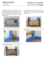
Join the end frames
Place one end frame on the floor with the brackets
pointing upwards, position a long beam over each
bracket, ensuring the small groove in the beam is
uppermost. Place the other end frame over the beams
and tighten the grub screws ensuring there are no
gaps between the beam end and the legs.
Fit the moulded leg-end caps.
➤
Workbench or Table Extension SECTION 2
When ordering an extension unit to an existing standard bench, order one end frame with the same order prefix as the bench. e.g.
Order a PA01 end frame to extend a PA03 bench.
Then order the beams and brackets bearing in mind the leg is 4cm (1
9
/16
”) square.
Plastic trim is also available seperately.
Assemble the end frame as in Section 1;
Attach the joining brackets to the legs on the side of the bench being extended;
Position the beams and end frame then tighten the grub screws ensuring there are no gaps between the ends of the
beams and the legs.

ITEM PD02 PD07
Grub Screw 42 42
Joining
Bracket 14 14
Screw 9 9
Work Top Clip 6 6
Leg-End Cap 4 4
Cap screw 6 6
Washer 6 6
You should have :
Single Matboard Storage Unit SECTION 3
ITEM PD02 PD07
Base Channel 10 7
Dividing Rod 33 24
Fixing Channel 2 2
Dividing
Rod Support 3 3
Leg 4 4
Beam 3+4 3+4
ITEM QTY
Allen Key 1
Spacer 1
TOOLS
Put a grub screw backwards into each of the joining brackets - do not place grub screws in the other holes
at this stage.
✓
✗
NOTE:
If you are assembling an extension unit with a standard unit –
go to section 5

Using the spacer, fit two brackets to the top of each leg ensuring the brackets are fitted the correct way round - with the flat
faces towards each other.
Attach joining brackets to the bottom
of the legs, again using the spacer, position
them as shown.
Put grub screws in each of the two large
holes in every bracket, only screw them in
by 2 or 3 turns.
➤
✓
✘
➠
➠
➠
FOR L.H. FOR R.H.
END FRAME END FRAME
➤
Make the end frames
Lay the two legs for the LH end frame on the floor together
and two of the set of four beams. Slide a fixing channel in
the top beam - take note of the relative positions of the
brackets in the drawing and the diamond hole in the fixing
channel.
Fix the legs over the brackets and tighten all the grub
screws using the long end of the allen key. Ensure there are
no gaps between the ends of the beams and the legs, then
lock the grub screws using the short end of the allen key.
Remember to ensure the groove in the
beam is on top.
Repeat for the RH frame.
➠
BOTTOM
L.H. FRAME
TOP

Join the end frames
Position the beams (set of 3) on the end frames as shown, again ensuring the groove in the beam is at the top. Tighten the grub
screws ensuring there are no gaps between the beam ends and the legs.
Repeat for the RH frame.
Remember to ensure the groove in the
beam is on top.
➤
Fit leg-end caps
Carefully trim the leg-end caps as shown. Keeping your fingers behind the blade at all times.
➠
BOTTOM
R.H. FRAME
TOP

Fitting the base channels
Place the unit in its final position, once the base channels are fitted
the unit can be dragged but not lifted
.
Slide the base channels in place starting from the outside working
towards the centre. Ensure the set of holes in the edges are towards
the front of the unit.
The two channels on the outside fit tight to the inside of the beam
leaving a small gap at the back of the channel.
Fitting the dividing rod supports &
dividing rods
Fit the dividing rod supports inside the top beams as
shown, using the cap screws and washers.
Note:- ensure the fixing channel is pushed to the back
of the unit.
Offer each rod up into the slot (this may be a tight fit -
this stops the rods rattling when in use).
Pull the rods down and push into the holes in the base channels.
➠
GAP
➠
➠
➠

ITEM PR02 PR07
Grub Screw 30 30
Joining
Bracket 10 10
Screw 7 7
Work Top Clip 4 4
Leg-End Cap 2 2
long Cap
screw 3 3
Nut 3 3
Washer 6 6
You should have :
Adding a Matboard Storage Unit Extension SECTION 4
ITEM PR02 PR07
Base Channel 10 7
Dividing Rod 33 24
Beam with
holes 1 1
Dividing
Rod Support 3 3
Leg 4 4
Beam 3+4 3+4
ITEM QTY
Allen Key 1
Spacer 1
TOOLS
Put a grub screw backwards into each of the joining brackets - do not place grub screws in the other holes
at this stage.
✓
✗
NOTE:
If you are assembling an Matboard Storage unit with an extension unit
–
– go to section 5

Attach the Joining brackets to the legs
Using the spacer, fit the joining brackets to the top of each leg
NOTE:- Ensure the joining brackets are fitted the correct
way round.
Make the Centre frame
Assemble the frame using the beam with holes and the other single
beam of the same length. ensure the beam with holes is assembled
the correct way round (see diagram)
Tighten all the grub screws using the long end of the allen key. ensure
there are no gaps between the ends of the beams and the legs, then
lock the grub screws using the short end of the allen key.
Change the frame on your existing unit
Remove the worktop from your existing unit then:-
Either Remove the dividing rods and dividing rod supports from
your existing unit
Or Hold the dividing rod supports in place with a length of timber
fixed to the unit with strong tape or string.
Remove the screws and
washers attaching the
dividing rod supports
to the end frames.
Put grub screws in each of
the two large holes in every
bracket, only screw them in
by 2 or 3 turns.
HOLES TOWARDS
THE BACK
REMOVE SCREWS AND
WASHERS
SIDE TO BE EXTENDED
TIMBER
FRONT LEG
BACK LEG
TIMBER
TAPE OR
STRING
BACK LEG FRONT LEG

(Continued)
Release the grub screws to remove
the end frame and replace it with the
centre frame.
NOTE:- Rod supports are not show
for clarity.
Complete the frame work
Using the set of 3 beams assemble the
unit as shown. Ensure all grub screws
are tightened fully and there are no gaps
between the beam ends and legs.
Fitting the leg-end caps
Carefully trim the leg-end caps as
shown, keeping your fingers behind the
blade at all times.
➤

Fitting the dividers
Place the dividing rod supports as shown, using the short cap
screws and washers removed earlier, to hold the supports to the
end of the unit.
Offer each rod up into the slot (this may be a tight fit -
this stops the rods rattling when in use).
Pull the rods down and push into the holes in the base channels.
Fitting the base channels
Slide the base channels in place starting
from the outside working towards the
centre. Ensure the set of holes in the edges
are towards the front of the unit.
The two channels on the outside
fit tight to the inside of the
beam leaving a small
gap at the back of
the channel.
➠
GAP
➠
➠
➠
BEAM
BEAM
LEG
BEAM
NUT
WASHER
WASHER
DIVIDING ROD
SUPPORT
DIVIDING ROD
SUPPORT
DIVIDING ROD
SUPPORT
LONG CAP
SCREW
SHORT CAP
SCREW

Matboard Storage Unit with Extension SECTION 5
NOTE:
If you are adding an extension to an existing Matboard Storage Unit
– go to section 4. For a Parts List refer to the beginning of:
Section 3 – Matboard Storage unit PD02 & PD07
Section 4 – Matboard Storage unit extension PR02 & PR07
Put a grub screw backwards into each of the joining brackets - do not place grub screws in the other holes
at this stage.
✓
✗
Attach the joining brackets to the legs
Using the spacer, fit two brackets to the top of 4 legs ensuring the brackets are fitted the correct way round - with the flat
faces towards each other.
Attach joining brackets to the bottom
of the legs, using the spacer. Position them
as shown in the diagram. These will make
the left & right hand end frames
➤
✓
✘
➠
➠
➠
FOR L.H. FOR R.H.
END FRAME END FRAME

(Continued)
Using the spacer, fit the joining brackets to the other two legs
as shown, these will make the centre frame.
NOTE:- Ensure the joining brackets are fitted the correct
way round.
Put grub screws in each of
the two large holes in every
bracket, only screw them in
by 2 or 3 turns.
➤
Make the end frames
Lay the two legs for the LH end frame on the floor together
and two of the set of four beams. Slide a fixing channel in
the top beam - take note of the relative positions of the
brackets in the drawing and the diamond hole in the fixing
channel.
Fix the legs over the brackets and tighten all the grub
screws using the long end of the allen key. Ensure there are
no gaps between the ends of the beams and the legs, then
lock the grub screws usingthe short end of the allen key.
Remember to ensure the groove in the
beam is on top.
Repeat for the RH frame.
➠
BOTTOM
L.H. FRAME
TOP
➤
➠
BOTTOM
R.H. FRAME
TOP
BACK LEG FRONT LEG
FOR CENTRE FRAME

Make the Centre frame
Assemble the frame using the beam with holes and the other single
beam of the same length. ensure the beam with holes is assembled
the correct way round (see diagram)
Tighten all the grub screws using the long end of the allen key. ensure
there are no gaps between the ends of the beams and the legs, then
lock the grub screws using the short end of the allen key.
Assemble the frame work
Using the remainder of the beams assem-
ble the framework as shown. Start from one
end frame and attach 3 beams, then the
centre frame,3 beams and then the
remaining end frame. Ensure all grub
screws are tightened fully
and there are no
gaps between
the beam ends
and legs.
➤
Fitting the leg-end caps
Carefully trim the leg-end caps as
shown, keeping your fingers behind the
blade at all times.
R.H. END
FRAME
L.H. END
FRAME
CENTRE
FRAME
HOLES TOWARDS
THE BACK
FRONT LEG
BACK LEG
CENTRE FRAME

Fitting the dividers
Place the dividing rod supports as shown, using the short cap
screws and washers removed earlier, to hold the supports to the
end of the unit.
Offer each rod up into the slot (this may be a tight fit -
this stops the rods rattling when in use).
Pull the rods down and push into the holes in the base channels.
Fitting the base channels
Slide the base channels in place starting
from the outside working towards the
centre. Ensure the set of holes in the edges
are towards the front of the unit.
The two channels on the outside
fit tight to the inside of the
beam leaving a small
gap at the back of
the channel.
➠
GAP
➠
➠
➠
BEAM
BEAM
LEG
BEAM
NUT
WASHER
WASHER
DIVIDING ROD
SUPPORT
DIVIDING ROD
SUPPORT
DIVIDING ROD
SUPPORT
LONG CAP
SCREW
SHORT CAP
SCREW

Cut the fabric larger than the worktop allowing about 10cm
(4”) overhang on all four sides. Apply tape or adhesive
around the edges and to the middle of the worktop.
Covering the worktop with fabric SECTION 6
Worktops can be covered with many types of worksurface, the Proteus covering (PN01/2/3) is a grey non woven fabric which will not
fray or unravel and can be moulded around worktop corners.
Proteus worktop fabric has a smooth upper surface and slightly rougher underside to key into adhesives. Use double sided carpet
tape, carpet/flooring adhesive or staples.
Fold the sides of the fabric down and pinch the flap made
in each corner, trim with scissors.
Fold the fabric to the underside, again pinch and trim. A
few staples in the underside will ensure the fabric is held in
place whilst the adhesive cures.
TOP
APPLY
DOUBLE SIDED
TAPE OR ADHESIVE
PINCH
PINCH
UNDERSIDE
ALSO APPLY
AROUND
EDGE ON
UNDERSIDE
➠
➠
➠
➠
✄
✄
/