
Installation Guide
SBX IP 320

Vertical Communications, Inc. reserves the right to revise this publication and to make changes in con-
tent without notice.
© 2007 by Vertical Communications, Inc. All rights reserved.
This publication contains proprietary and confidential information of Vertical Communications, Inc.
The contents of this document may not be disclosed, copied or translated by third parties, in any form,
or by any means known, or not now known or conceived, without prior explicit written permission from
Vertical Communications, Inc.
LIMIT OF LIABILITY/DISCLAIMER OF WARRANTY
Vertical Communications, Inc. makes no representation or warranties with respect to the accuracy or
completeness of the content of this publication and specifically disclaims any implied warranty of mer-
chantability or fitness for any particular purpose, and shall not be liable for any loss of profit or any other
commercial damage, including but not limited to, special, incidental, or consequential.
TRADEMARKS
Vertical Communications and the Vertical Communications logo and combinations thereof are trade-
marks of Vertical Communications, Inc. All other brand and product names are used for identification
only and are the property of their respective holders.
RESTRICTED RIGHTS LEGEND
Use, duplication, or disclosure of the technical data contained in this document by the Government is
subject to restrictions as set forth in subdivision (c) (1) (ii) of the Rights in Technical Data and Computer
Software clause at DFARS 52.227-7013 and/or in similar or successor clauses in the FAR, or in the
DOD or NASA FAR Supplement. Unpublished rights reserved under the Copyright Laws of the United
States. Contractor/manufacturer is Vertical Communications, Inc., 10 Canal Park, Suite 602, Cambridge,
MA 02141-2249.

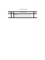
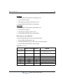
REVISION HISTORY
Release Date Documentation Changes Page No.
1.0 01-08
Initial Release
NOTE: that this document contains information on ISDN,
DCOB, and SMS. These features are currently not supported.
Information pertaining to DID pertains only to SIP Trunking.
--


SBX IP 320 Installation Guide
Contents
Chapter 1 Introduction
Important Safety Instructions - - - - - - - - - - - - - - - - - - - - - - - - - 1-1
Safety Requirements - - - - - - - - - - - - - - - - - - - - - - - - - - - - 1-1
Precautions - - - - - - - - - - - - - - - - - - - - - - - - - - - - - - - - - - 1-2
Cautions - - - - - - - - - - - - - - - - - - - - - - - - - - - - - - - - - - - - 1-3
Disposal of Old Appliances - - - - - - - - - - - - - - - - - - - - - - - 1-3
Manual Usage - - - - - - - - - - - - - - - - - - - - - - - - - - - - - - - - - - - 1-4
Chapter 2 System Overview
SBX IP 320 System Highlights - - - - - - - - - - - - - - - - - - - - - - - - 2-1
System Connection Diagram - - - - - - - - - - - - - - - - - - - - - - - - - 2-2
System Components - - - - - - - - - - - - - - - - - - - - - - - - - - - - - - 2-3
Specifications - - - - - - - - - - - - - - - - - - - - - - - - - - - - - - - - - - - 2-4
Chapter 3 KSU Installation
Pre-Installation - - - - - - - - - - - - - - - - - - - - - - - - - - - - - - - - - - - 3-1
Safety Installation Instructions - - - - - - - - - - - - - - - - - - - - - 3-1
Installation Precautions - - - - - - - - - - - - - - - - - - - - - - - - - - 3-1
Wiring Precautions - - - - - - - - - - - - - - - - - - - - - - - - - - - - - 3-2
KSU Installation - - - - - - - - - - - - - - - - - - - - - - - - - - - - - - - - - - 3-3
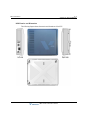
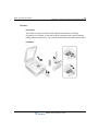
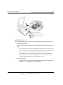
Unpacking - - - - - - - - - - - - - - - - - - - - - - - - - - - - - - - - - - - 3-3
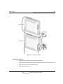
KSU Exterior and Dimension - - - - - - - - - - - - - - - - - - - - - - 3-4
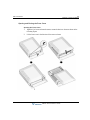
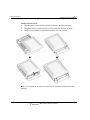
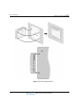
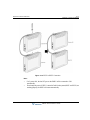
Opening and Closing the Front Cover - - - - - - - - - - - - - - - - 3-5
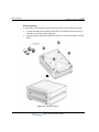
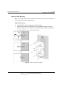
Power Supply Unit Installation - - - - - - - - - - - - - - - - - - - - - 3-7
Frame Ground Connection - - - - - - - - - - - - - - - - - - - - - - - - 3-8
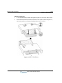
External Backup Battery Installation - - - - - - - - - - - - - - - - - 3-9
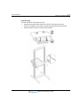
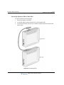
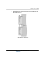
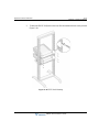
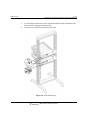
KSU Mounting - - - - - - - - - - - - - - - - - - - - - - - - - - - - - - - 3-10
Expansion KSU Installation - - - - - - - - - - - - - - - - - - - - - - - - - 3-15
Unpacking - - - - - - - - - - - - - - - - - - - - - - - - - - - - - - - - - - 3-15

Contents TOC-2
SBX IP 320 Installation Guide
Connecting Expansion KSU to Basic KSU - - - - - - - - - - - - 3-16
Expansion KSU Mounting - - - - - - - - - - - - - - - - - - - - - - - - 3-18
Chapter 4 Board Installation
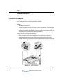
Installation of the Boards - - - - - - - - - - - - - - - - - - - - - - - - - - - - 4-1
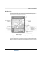
Main Board Unit - - - - - - - - - - - - - - - - - - - - - - - - - - - - - - - - - - - 4-2
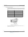
Modular Jack (MJ1 - MJ3) Pin Assignment - - - - - - - - - - - - - 4-4
Switch, LED, and Connector - - - - - - - - - - - - - - - - - - - - - - - 4-6
Expansion Main Board Unit (EMBU/NTB412) - - - - - - - - - - - - - - 4-7
Modular Jack (MJ1 - MJ3) Pin Assignment - - - - - - - - - - - - 4-10
Installation of the CO Line & Extension Board - - - - - - - - - - - - 4-11
CHB308 (3 CO Line and 8 Hybrid Interface Board/NTB417) - - -
4-11
VOIB (Voice over Internet protocol Board (4ch)/NTB422) - - 4-13
Other Board Installations - - - - - - - - - - - - - - - - - - - - - - - - - - - 4-16
Voice Mail Interface Unit (VMIU/NTB420) - - - - - - - - - - - - - 4-16
Modem Function Unit (MODU/NTB413) - - - - - - - - - - - - - - 4-17
Chapter 5 Terminal Connection And Wiring Method
Terminal and Doorbox Models - - - - - - - - - - - - - - - - - - - - - - - - 5-1
Terminal Cabling Distance - - - - - - - - - - - - - - - - - - - - - - - - - - - 5-3
Basic Terminal Connection - - - - - - - - - - - - - - - - - - - - - - - - - - - 5-4
DKT and DSS - - - - - - - - - - - - - - - - - - - - - - - - - - - - - - - - - 5-4
SLT - - - - - - - - - - - - - - - - - - - - - - - - - - - - - - - - - - - - - - - - - 5-4
Doorbox - - - - - - - - - - - - - - - - - - - - - - - - - - - - - - - - - - - - - 5-5
Connecting Additional Terminals - - - - - - - - - - - - - - - - - - - - - - - 5-7
External Music Source Wiring - - - - - - - - - - - - - - - - - - - - - - 5-7
Relay Contacts - - - - - - - - - - - - - - - - - - - - - - - - - - - - - - - - 5-7
External Paging Port Wiring - - - - - - - - - - - - - - - - - - - - - - - 5-8
Alarm Detection Wiring - - - - - - - - - - - - - - - - - - - - - - - - - - - 5-8
Cable Wiring - - - - - - - - - - - - - - - - - - - - - - - - - - - - - - - - - - - - - 5-8
Wall Mount Wiring - - - - - - - - - - - - - - - - - - - - - - - - - - - - - - 5-8
Rack Mount Wiring - - - - - - - - - - - - - - - - - - - - - - - - - - - - - - 5-9

Contents TOC-3
SBX IP 320 Installation Guide
Chapter 6 Starting the SBX IP 320
Before Starting the SBX IP 320 - - - - - - - - - - - - - - - - - - - - - - - 6-1
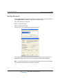
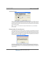
Basic Programming - - - - - - - - - - - - - - - - - - - - - - - - - - - - - - - 6-1
DKT Programming - - - - - - - - - - - - - - - - - - - - - - - - - - - - - 6-1
Entering the Programming Mode - - - - - - - - - - - - - - - - - - - 6-4
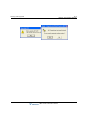
Pre-Programming - - - - - - - - - - - - - - - - - - - - - - - - - - - - - - 6-5
Chapter 7 Using Database Upload/Download
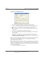
General Description - - - - - - - - - - - - - - - - - - - - - - - - - - - - 7-1
PC Requirement - - - - - - - - - - - - - - - - - - - - - - - - - - - - - - - 7-1
Connection Method with SBX IP 320 - - - - - - - - - - - - - - - - 7-1
SBXIP 320 MPB S/W Version Compatibility - - - - - - - - - - - - 7-2
Installation - - - - - - - - - - - - - - - - - - - - - - - - - - - - - - - - - - - - - - 7-2
File Component in your Execution Directory - - - - - - - - - - - 7-2
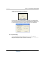
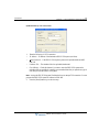
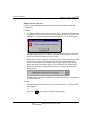
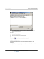
Choosing Up/Download and Connection Type - - - - - - - - - - 7-2
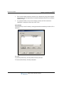
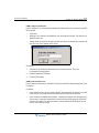
User Information Dialog - - - - - - - - - - - - - - - - - - - - - - - - - - 7-3
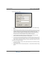
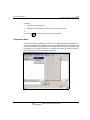
Starting Database File Upload/Download - - - - - - - - - - - - - - - - 7-7
Transferring Process - - - - - - - - - - - - - - - - - - - - - - - - - - - - 7-8
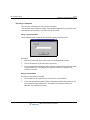
Finishing DataBase File Upload/Download - - - - - - - - - - - - 7-8
Chapter 8 Software Upgrade
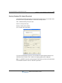
General Description - - - - - - - - - - - - - - - - - - - - - - - - - - - - 8-1
PC Requirement - - - - - - - - - - - - - - - - - - - - - - - - - - - - - - - 8-1
Connection Method with SBX IP 320 - - - - - - - - - - - - - - - - 8-1
SBX IP 320 MPB S/W Version Compatibility - - - - - - - - - - - 8-2
Installation - - - - - - - - - - - - - - - - - - - - - - - - - - - - - - - - - - - - - - 8-2
File Component in your Execution Directory - - - - - - - - - - - 8-2
Choosing Up/Download and Connection Type - - - - - - - - - - 8-2
User Information Dialog - - - - - - - - - - - - - - - - - - - - - - - - - - 8-3
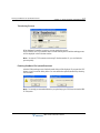
Starting S/W Upgrade - - - - - - - - - - - - - - - - - - - - - - - - - - - - - - 8-6
Transferring Process - - - - - - - - - - - - - - - - - - - - - - - - - - - - 8-7
Finishing DataBase File Upload/Download - - - - - - - - - - - - 8-7
Chapter 9 Remote Diagnostics
Introduction - - - - - - - - - - - - - - - - - - - - - - - - - - - - - - - - - - - - - 9-1

Contents TOC-4
SBX IP 320 Installation Guide
Hardware/Software Requirements - - - - - - - - - - - - - - - - - - - 9-1
Hardware Configuration - - - - - - - - - - - - - - - - - - - - - - - - - - 9-2
Uninstalling Software - - - - - - - - - - - - - - - - - - - - - - - - - - - - 9-2
Important Notes for Users - - - - - - - - - - - - - - - - - - - - - - - - - 9-3
Full Screen Layout - - - - - - - - - - - - - - - - - - - - - - - - - - - - - - 9-4
[File] Menu - - - - - - - - - - - - - - - - - - - - - - - - - - - - - - - - - - - - - - 9-4
[Open] Sub-menu - - - - - - - - - - - - - - - - - - - - - - - - - - - - - - - 9-5
[Capture On] Sub-menu - - - - - - - - - - - - - - - - - - - - - - - - - - 9-5
[Capture Off] Sub-menu - - - - - - - - - - - - - - - - - - - - - - - - - - 9-5
[Connection] Menu - - - - - - - - - - - - - - - - - - - - - - - - - - - - - - - - - 9-6
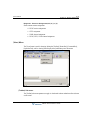
Serial Port Connection with SBX IP 320System - - - - - - - - - 9-6
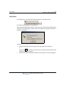
Modem Connection with the SBX IP 320 System - - - - - - - - 9-9
LAN Connection with the SBX IP 320 System - - - - - - - - - - 9-18
[Commands] Menu - - - - - - - - - - - - - - - - - - - - - - - - - - - - - - - 9-21
Executing Commands - - - - - - - - - - - - - - - - - - - - - - - - - - - 9-22
Functions of Commands - - - - - - - - - - - - - - - - - - - - - - - - - 9-24
[View] Menu - - - - - - - - - - - - - - - - - - - - - - - - - - - - - - - - - - - - 9-37
[Toolbar] Sub-menu - - - - - - - - - - - - - - - - - - - - - - - - - - - - 9-37
[Command Bar] Sub-menu - - - - - - - - - - - - - - - - - - - - - - - 9-38
[Input Box Bar] Sub-menu - - - - - - - - - - - - - - - - - - - - - - - - 9-38
[Clear New] Sub-Menu - - - - - - - - - - - - - - - - - - - - - - - - - - 9-38
[Help] Menu - - - - - - - - - - - - - - - - - - - - - - - - - - - - - - - - - - - - 9-39
[Data Display Area] - - - - - - - - - - - - - - - - - - - - - - - - - - - - - - - 9-40
Data Display Functions - - - - - - - - - - - - - - - - - - - - - - - - - - 9-40
Automatic Data Storing Functions - - - - - - - - - - - - - - - - - - 9-41
Important Note for Users - - - - - - - - - - - - - - - - - - - - - - - - - 9-41
Chapter 10 Troubleshooting
Index

SBX IP 320 Installation Guide
Chapter 1
Introduction
Important Safety Instructions
Safety Requirements
When using your telephone equipment, basic safety precautions should always be followed to
reduce the risk of fire, electric shock and other personal injury, including the following:
• Please read and understand all instructions.
• Follow all warnings and instructions marked on the product.
• Unplug this product from the wall outlet before cleaning. A damp cloth should be used
for cleaning; do not use liquid or aerosol cleaners.
• Do not use this product near water, such as in a bathtub, washbowl, kitchen sink, or
laundry tub, in a wet basement, or near a swimming pool.
• Do not place this product on an unstable card, stand, or table. The product may fall,
causing serious damage to the product or serious injury.
• Slots and openings in the KSU and the back or bottom are provided for ventilation and to
protect it from overheating. These openings must not be blocked or covered. The
openings should never be blocked by placing the product on a bed, sofa, or other similar
surface. This product should never be placed near or over a radiator or other heat source.
This product should not be placed in a built-in installation without proper ventilation.
• This product should be operated only from the type of power source indicated on the
product label. If you are not sure of the type of power supply to your location, consult
your dealer or local power company.
• Do not allow anything to rest on the power cord. Do not locate this product where the
cord could be abused by people walking on it.
• Do not overload wall outlets and extension cords as this can result in the risk of fire or
electric shock.
• Never push objects of any kind into this product through KSU slots or connectors as they
may touch dangerous voltage points or short out parts that could result in a risk of fire or
electric shock.

Important Safety Instructions 1-2
Chapter 1: Introduction
SBX IP 320 Installation Guide
• Never spill liquid of any kind on the product.
• To reduce the risk of electric shock, do not disassemble this product. Instead, take it to a
qualified person when service or repair work is required. Opening or removing covers
may expose you to dangerous voltages or other risk. Incorrect reassemble can cause
electric shock when the appliance is subsequently used.
• Unplug this product from the wall outlet and refer servicing to qualified service personnel
under the following conditions:
• When the power supply cord or plug is damaged or frayed.
• If liquid has been spilled into the product.
• If the product has been exposed to rain or water.
• If the product does not operate normally by following the operating instructions.
Adjust only those controls that are covered by the operating instructions because
improper adjustment of other controls may result in damage and will often require
extensive work by a qualified technician to restore the product to normal
operation.
• If the product has been dropped or the KSU has been damaged.
• If the product exhibits a distinct change in performance.
• Avoid using a telephone during an electrical storm. There may be a remote risk of electric
shock from lightning.
• In the event of a gas leak, do not use the telephone near the leak.
Precautions
• Keep the system away from heating appliances and electrical noise generating devices
such as florescent lamps, motors and televisions. These noise sources can interfere with
the performance of the SBX IP 320 System.
• This system should be kept free of dust, moisture, high temperature (more than 40
degrees) and vibration, and should not be exposed to direct sunlight.
• Do not attempt to insert wires, pins, etc. into system. If system does not operate properly,
the equipment should be repaired by an authorized service center.
• Do not use benzene, paint thinner, or an abrasive powder to clean the KSU. Wipe it with
a soft cloth only.

Important Safety Instructions 1-3
Chapter 1: Introduction
SBX IP 320 Installation Guide
Cautions
• This system should only be installed and serviced by qualified service personnel.
• When a failure occurs which exposes any internal parts, disconnect the power supply
cord immediately and return this system to your dealer.
• To prevent the risk of fire, electric shock or energy hazard, do not expose this product to
rain or any type of moisture.
• To protect the PCB from static electricity, discharge body static before touching
connectors and/or components by touching ground or wearing a ground strap.
Warning: Danger of explosion if battery is not correctly replaced. Replace only with the same
or equivalent type recommended by the manufacturer. Dispose of used batteries according to
the manufacturer’s instructions.
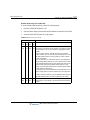
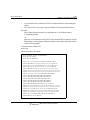
Disposal of Old Appliances
When the displayed symbol (crossed-out wheeled bin) is adhered to a product, it designates the
product is covered by the European Directive 2002/96/EC.
•All electric and electronic products should be only be disposed
of in special collection facilities appointed by government or
local/municipal authorities.
•The correct disposal of your old appliance will help prevent
potential negative consequences for the environment and
human health.
•For more detailed information about disposal of your old
appliances, please contact your city office, waste disposal
service or the place of product purchase.

Manual Usage 1-4
Chapter 1: Introduction
SBX IP 320 Installation Guide
Manual Usage
This document provides general information covering the hardware description and installation
of the SBX IP 320 System. While every effort has been taken to ensure the accuracy of this
information Vertical Communications, Inc makes no warranty of accuracy or interpretations
thereof.
Chapter 2. System Overview
Provides general information on the SBX IP 320 System, including the system specifications
and capacity.
Chapter 3. KSU Installation
Describes detailed instructions for planning the installation site and procedures to install the
SBX IP 320 System.
Chapter 4. Board Installation
Describes detailed instructions for installing components of the SBX IP 320 Board.
Chapter 5. Terminal Connections and Wiring Method
Describes the kinds of terminals, maximum distance, and other device connections for the
terminal.
Chapter 6. Starting the SBX IP 320 System
Provides general information for starting the System and basic Admin programming.
Chapter 7. Database Download/Upload
Describes Database Download and Upload procedures.
Chapter 8. Software Upgrade
Describes Software Upgrade procedures.
Chapter 9. Remote Diagnostics
Describes Remote Diagnostics procedures.
Chapter 10. Troubleshooting
Provides information on the SBX IP 320 System and deals with common troubleshooting
issues.

SBX IP 320 Installation Guide
Chapter 2
System Overview
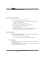
SBX IP 320 System Highlights
Features of the SBX IP 320 System include:
• Flexible architecture
• Simplifying system structure
• Powerful PC application via LAN, Modem, RS-232C
• Stable & Enhanced voice features
• Simple installation & efficient system management
• Remote admin & software upgrade through LAN connection
• Remote admin & software upgrade through PSTN modem
• Value-Added features
• Distinctive voice mail (ADPCM 32 Kbps)
• Basic CID (CO & SLT) Function
• 8 Poly internal MOH (13 Music sources)

System Connection Diagram 2-2
Chapter 2: System Overview
SBX IP 320 Installation Guide
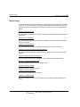
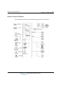
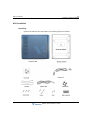
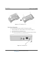
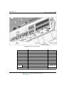
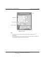
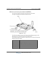
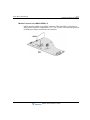
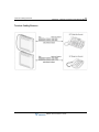
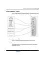
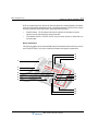
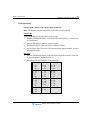
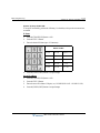
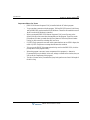
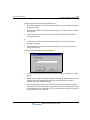
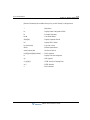
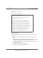
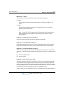
System Connection Diagram
The following Figure shows the components that make up the SBX IP 320 System:
SBX IP 320

System Components 2-3
Chapter 2: System Overview
SBX IP 320 Installation Guide
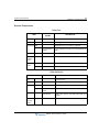
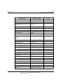
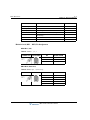
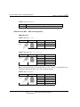
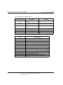
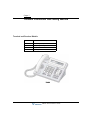
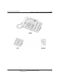
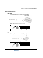
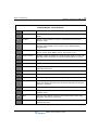
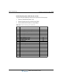
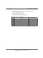
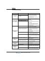
System Components
BASIC KSU
EXPANSION KSU
ITEM
OPTION
BOARD
DESCRIPTION
KSU Key Service Unit
PSU Power Supply Unit
Main Board MBU Main Board Unit (3 CO, 1 DKT, & 7 Hybrid)
CO & Extension
Boards
CO Line and DKT/SLT Interface Boards (CHB308 and
VOIB)
Other Boards VMIU & MODU can be installed
CO Line &
Extension
Boards
CHB308 3 CO Lines and 8 Hybrid Interface Board
Other
Boards
VMIU Voice Mail Interface Unit, 4 channels
MODU MODEM unit (33 Kbps)
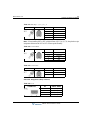
ITEM OPTION BOARD DESCRIPTION
KSU Key Service Unit
PSU Power Supply Unit
Main Board EMBU Expansion Main Board Unit (3 CO & 8 Hybrid)
CO & Extension
Board
CO Line and DKT/SLT Interface Board (CHB308)
Other Boards VMIU, AAFU, MODU, CMU50PR, CMU12PR can be
installed
CO Line &
Extension
Boards
CHB308 3 CO Lines and 8 Hybrid Interface Board

Specifications 2-4
Chapter 2: System Overview
SBX IP 320 Installation Guide
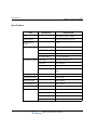
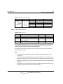
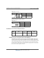
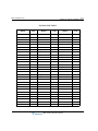
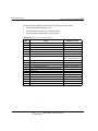
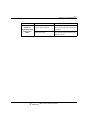
Specifications
ITEM DESCRIPTION SPECIFICATION
CPU ARM7 TDMI core(32bit, 50MHz)
Switching Device Custom Mixed-Signal ASIC Device
Memory Back-up
Duration
10 years
PSU AC Voltage Input 100-240 +/- 10% Volt AC @47-63Hz
AC Power Consumption 90W
AC Input Fuse 2A @250Volt AC
DC Output Voltage +5, -5, +27, +30Volt DC
External Back-up Battery Input Voltage +24 Volt DC(+12VDC x 2ea)
Battery Fuse 5.0A @250Volt AC
Charging Current Max. 200mA
Battery Load Current Max. 3A (only BKSU), Max. 6A ( BKSU +
EKSU)
Ring Signal 75Vrms, 25Hz
External Relay Contact 1A @ 30Volt DC
Music Source Input 0dBm @ 600ohm
External Paging Port 0dBm @ 600ohm
Ring Detect Sensitivity 30Vrms @ 16-55Hz
DTMF Dialing Frequency Deviation Less than +/-1.8%
Signal Rise Time 5 ms
Tone Duration, on time Min. 50 ms, Normally 100 ms
Inter-digit Time Min. 30 ms, Normally 100 ms

Specifications 2-5
Chapter 2: System Overview
SBX IP 320 Installation Guide
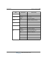
Pulse Dialing Pulse Rate 10 PPS
Break/Make Ratio 60/40% or 66/33%
Operating Environment Temperature 0 (
o
C) – 40 (
o
C)
Humidity 0 - 80% (non-condensing)
Dimension KSU 339mm(W) x 288mm(H) x 85mm(D)
Expansion KSU 339mm(W) x 288mm(H) x 85mm(D)
Weight KSU 1.8 Kg
Expansion KSU 1.8 Kg
MODU Analog Modem Bell, ITU-T, V.34 V.32BIS, V.90
Speed 300bps up to 33Kbps speed rate
Connection Automatic rate negotiation
VOIB LAN Interface 10 Base-T Ethernet (IEEE 802.3)
Speed 10 Mbps (Auto-Negotiation)
Duplex Half Duplex or Full Duplex (Auto-Negotiation)
VOIP Protocol H.323 Revision 2
Voice Compression G.711/G.726/G729/G.723.1
Voice/Fax Switching T.38
Echo Cancellation G.165
ITEM DESCRIPTION SPECIFICATION

Specifications 2-6
Chapter 2: System Overview
SBX IP 320 Installation Guide
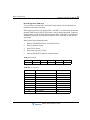
DESCRIPTION CAPACITY/BOARD TOTAL
Time Slots 128
CO Line Ports 4/CHB308 12
Max Direct Station (DKT, SLT, DSS)
Connections
4/CHB308 32
External Relay Contact 2/MBU 2
LAN MBU, VOIB, E1HB8 3
MODEM Channel 1/MODU 1
Attendant Positions 5/System
Intercom Links Non-Blocking
Paging
- All Call
- Internal
1 zone
5 zones
Station Speed Dial 100/station, 24 digits each 500
System Speed Dial 24 digits each 500
Last Number Redial 15-50 (by admin programming 32 digits
CO Line Group 8 8
Station Group 10 10
Conference 3-15 Party All ports are available
Multi-Conference 3-15 Party Max. 3 groups
Internal MOH (13 Music Sources) 1/MBU 1
External MOH 1/MBU 1
External Paging Port 1/MBU 1
External Relay Contact 2/MBU, 2/EMBU 4
Alarm Input 1/MBU 1
RS-232C Port 1/MBU 1
DTMF/CPT Receiver Channels 16 chs/MBU 16 chs
FSK Receiver Channels 16 chs/MBU 16 chs
PFT Circuit 1/MBU, !/EMBU, 1/CHB308 3

SBX IP 320 Installation Guide
Chapter 3
KSU Installation
Pre-Installation
Please read the following guidelines concerning installation and connection before installing the
SBX IP 320 System. Be sure to comply with applicable local regulations.
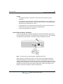
Safety Installation Instructions
When installing the telephone wiring, basic safety precautions should always be followed to
reduce the risk of fire, electric shock and personal injury, including the following:
• Never install the telephone wiring during a lightning story.
• Never install the telephone jack in wet locations unless the jack is specifically designed
for wet locations.
• Never touch un-insulated telephone wires or terminals unless the telephone line has been
disconnected at the network interface.
• Use caution when installing or modifying telephone lines.
• Anti-static precautions should be taken during installation.
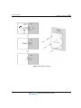
Installation Precautions
The SBX IP 320 System is designed for wall mounting or a free –standing rack. Avoid installing
in the following places:
• In direct sunlight and hot, cold, or humid places. Temperature range = 0 to 40
o
C.
• Places where shocks or vibrations are frequent or strong.
• Dusty places, or places where water or oil may come into contact with the System.
• Near high-frequency generating devices such as sewing machines or electric welders.
• On or near computers, fax machines, or other office equipment, as well as microwave
ovens or air conditioners.
• Do not obstruct the openings on the top of the SBX IP 320 System.

Pre-Installation 3-2
Chapter 3: KSU Installation
SBX IP 320 Installation Guide
• Do not stack up the optional service boards.
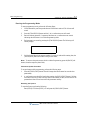
Wiring Precautions
Be sure to follow these precautions when wiring:
• Do not wire the telephone cable in parallel with an AC power source, such as a computer,
fax machine, etc. If the cables are run near those devices, shield the cables with metal
tubing or use shielded cables and ground the shields.
• If the cables are run on the floor, use protectors to prevent the wires from being stepped
on. Avoid wiring under carpets.
• Avoid using the same power supply outlet for computers, fax machine, and other office
equipment to avoid induction noise interruption when using the SBX IP 320 near other
machines.
• The power and battery switches must be OFF during wiring. After wiring is completed,
the power switch may be turned ON.
• Incorrect wiring may cause the SBX IP 320 System to operate improperly. If an
extension does not operate properly, disconnect the telephone from the extension line and
then re-connect, or turn the System power OFF and then ON again.
• Use twisted pair cable for connecting CO lines.
Page is loading ...
Page is loading ...
Page is loading ...
Page is loading ...
Page is loading ...
Page is loading ...
Page is loading ...
Page is loading ...
Page is loading ...
Page is loading ...
Page is loading ...
Page is loading ...
Page is loading ...
Page is loading ...
Page is loading ...
Page is loading ...
Page is loading ...
Page is loading ...
Page is loading ...
Page is loading ...
Page is loading ...
Page is loading ...
Page is loading ...
Page is loading ...
Page is loading ...
Page is loading ...
Page is loading ...
Page is loading ...
Page is loading ...
Page is loading ...
Page is loading ...
Page is loading ...
Page is loading ...
Page is loading ...
Page is loading ...
Page is loading ...
Page is loading ...
Page is loading ...
Page is loading ...
Page is loading ...
Page is loading ...
Page is loading ...
Page is loading ...
Page is loading ...
Page is loading ...
Page is loading ...
Page is loading ...
Page is loading ...
Page is loading ...
Page is loading ...
Page is loading ...
Page is loading ...
Page is loading ...
Page is loading ...
Page is loading ...
Page is loading ...
Page is loading ...
Page is loading ...
Page is loading ...
Page is loading ...
Page is loading ...
Page is loading ...
Page is loading ...
Page is loading ...
Page is loading ...
Page is loading ...
Page is loading ...
Page is loading ...
Page is loading ...
Page is loading ...
Page is loading ...
Page is loading ...
Page is loading ...
Page is loading ...
Page is loading ...
Page is loading ...
Page is loading ...
Page is loading ...
Page is loading ...
Page is loading ...
Page is loading ...
Page is loading ...
Page is loading ...
Page is loading ...
Page is loading ...
Page is loading ...
Page is loading ...
Page is loading ...
Page is loading ...
Page is loading ...
Page is loading ...
Page is loading ...
Page is loading ...
Page is loading ...
Page is loading ...
Page is loading ...
Page is loading ...
Page is loading ...
Page is loading ...
Page is loading ...
Page is loading ...
Page is loading ...
Page is loading ...
Page is loading ...
Page is loading ...
Page is loading ...
Page is loading ...
Page is loading ...
Page is loading ...
Page is loading ...
Page is loading ...
Page is loading ...
Page is loading ...
Page is loading ...
Page is loading ...
Page is loading ...
Page is loading ...
Page is loading ...
Page is loading ...
Page is loading ...
Page is loading ...
Page is loading ...
Page is loading ...
Page is loading ...
Page is loading ...
Page is loading ...
Page is loading ...
Page is loading ...
-
 1
1
-
 2
2
-
 3
3
-
 4
4
-
 5
5
-
 6
6
-
 7
7
-
 8
8
-
 9
9
-
 10
10
-
 11
11
-
 12
12
-
 13
13
-
 14
14
-
 15
15
-
 16
16
-
 17
17
-
 18
18
-
 19
19
-
 20
20
-
 21
21
-
 22
22
-
 23
23
-
 24
24
-
 25
25
-
 26
26
-
 27
27
-
 28
28
-
 29
29
-
 30
30
-
 31
31
-
 32
32
-
 33
33
-
 34
34
-
 35
35
-
 36
36
-
 37
37
-
 38
38
-
 39
39
-
 40
40
-
 41
41
-
 42
42
-
 43
43
-
 44
44
-
 45
45
-
 46
46
-
 47
47
-
 48
48
-
 49
49
-
 50
50
-
 51
51
-
 52
52
-
 53
53
-
 54
54
-
 55
55
-
 56
56
-
 57
57
-
 58
58
-
 59
59
-
 60
60
-
 61
61
-
 62
62
-
 63
63
-
 64
64
-
 65
65
-
 66
66
-
 67
67
-
 68
68
-
 69
69
-
 70
70
-
 71
71
-
 72
72
-
 73
73
-
 74
74
-
 75
75
-
 76
76
-
 77
77
-
 78
78
-
 79
79
-
 80
80
-
 81
81
-
 82
82
-
 83
83
-
 84
84
-
 85
85
-
 86
86
-
 87
87
-
 88
88
-
 89
89
-
 90
90
-
 91
91
-
 92
92
-
 93
93
-
 94
94
-
 95
95
-
 96
96
-
 97
97
-
 98
98
-
 99
99
-
 100
100
-
 101
101
-
 102
102
-
 103
103
-
 104
104
-
 105
105
-
 106
106
-
 107
107
-
 108
108
-
 109
109
-
 110
110
-
 111
111
-
 112
112
-
 113
113
-
 114
114
-
 115
115
-
 116
116
-
 117
117
-
 118
118
-
 119
119
-
 120
120
-
 121
121
-
 122
122
-
 123
123
-
 124
124
-
 125
125
-
 126
126
-
 127
127
-
 128
128
-
 129
129
-
 130
130
-
 131
131
-
 132
132
-
 133
133
-
 134
134
-
 135
135
-
 136
136
-
 137
137
-
 138
138
-
 139
139
-
 140
140
-
 141
141
-
 142
142
-
 143
143
-
 144
144
-
 145
145
-
 146
146
-
 147
147
-
 148
148


Ask a question and I''ll find the answer in the document
Finding information in a document is now easier with AI
Related papers
-
Vertical SBX IP 320 User Training Manual
-
-
-
-
-
-
-
-
-
Other documents
-
Aiphone IX Quikstart Guide
-
Aiphone IX-DA Quick Start Programming Manual
-
Siemens SLT-1-UK Upgrade Kit User manual
-
XBLUE Networks 45p Installation guide
-
Black Box Lineshare Pro FX150A User manual
-
 Comdial ExecuTech 0616 Series User manual
-
LG-Ericsson ipldk-60 Hardware Description And Installation Manual
-
Creative Sound BlasterAxx SBX 10 User manual
-
Ericsson LDP-7208D User manual
-
RTS Fiber optic interface back card single mode User manual
