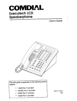
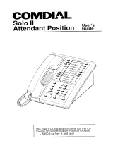
Comdial ExecuTech 0616 Series User manual
- Category
- Door intercom systems
- Type
- User manual
This manual is also suitable for

COMCHAL
ExecuTech
Model 0616X
&
0816X
Electronic Key Systems
This manual applicable for the following key system models:
l 0616X Manufacturing Code
8xxC
and Later
*
0816X
All
Ma~uf&cturing
Codes
1.
1
J
IMI
66-031.04
3/89

IMI 66-031
Table of Contents
TABLE OF CONTENTS
CHAPl-ERt
INTRODUCTION . . . . . . . . . . . . . . . . . . . . . . . . . . .
.;‘:
MANUAL SCOPERELATEDPUBLICATioN’S
. . . . . . . . . . . . . . . . . .
. . . . . .
-
fNSTALLEWUSER INFORMATION
REGARDING FCC RULES AND ‘REGULATIONS . . . . . . . . . . . . . . . . . l-l
CHAPTER 2 INSTALLATION
0
.
m
. . . .
0
. . . . . . . .
2-l
MOUNTtNGCONSIDERATldNS
l
:
l .
‘.
*
. l
:
:
:
. . . . . . . . . . . . . .
.2-l
MOUNTING PROCEDURE . . . . . . . . . . . . . . . . . . . . . . .
$2
SYSTEM WIRING . . . . . . . . . . . . . . . . . . . . . . . . . .
-
CHECKOUT . . . . . . . . . . . . . . . . . . . . . . . . . . . . .2-9
CHAPTER3 SYSTEM PROGRAMMING . . . . . . . . . . . . . . . . . . . . . . . . 3-l
GENERAL INFORMATION
.
f
-3-l
BASE LEVELPROGRAM ENTRY
hndDE
: : : :
:
: : : : : :
:
: : : : : . .
.3-l
CLASS OF SERVICE DEFAULT
PROGRAMMING KEYS
. . . . . . . . . . . . . . . . . . . .
:
:;-;
SYSTEM COS
PROGRAMM’ING
PkdCEDURE
.
:
: : : :
:
:
:
: : :
:
:
:
: . .
-3-3
LINE COS PROGRAMMING PROCEDURE
-3-5
STATIONCOSPROGRAMMING
PROCEDURE . : : :
:
: : : : : :
:
: : : :
\
3:
SMDR AND COS PRINTOUT
SYSTEMCLOCKINFORMATION.
:
: : : : : : :
:
: :
:
: : : : : : : : . 3-11
SYSTEM SPEED
DIAL
PROGRAMMING . . . . . . . . . . . . . . . . . . . 3-12
CHAPTER 4 MAINTENANCE
TECHNICAL ASSISTANCE AND REPAIR SERVICE
...
:
:
.......
Cl
FUSE LOCATION
..........................
FAILURE ISOLATION. : : : : : : : : : : : : : : : : : :
:4-i
-
.......
.4-l
PAIRED STATIONS
.........................
FAILURE ANALYSIS
:;-;
DESKIWALLREFERSALANbtiAiL
MOUNTINS
.
:
:
:
:
:
: :
:
:
: :
:
:
:
:
:
.4-4
PUBLICATIONINDEX
..............................
.bl
LIST OF TABLES
Table 2-l. KSU to Station Wiring
. . . . . . . . . . . . .
-2-7
Table 3-l. System COS Programming Reference .
:
1
:
. . . . . . . . . . . . . 3-13
Table 3-2. tine COS Programming Reference . . . . . . . . . . . . . . . . .
3-15
Table 3-3. Station COS Programming Reference
. . . . . . . . . . . . . . . .
i-i.t
Table 34. Toll Restriction
Programming.Reference
. . . . . . . . . . . . . . . .
-
Table 4-1. Station Pairing . . . . . . . . . . . . . . . . . . . . . . . . .4-3
LIST OF ILLUSTRATIONS
Figure 2-l.
Figure 2-2.
Figure 2-3.
Figure 2.4.
Figure
3-l.
Figure 3-2.
Figure 3-3.
Figure 3-4.
Figure 4-l.
Figure 4-2.
Mounting Dimensions
-2-2
External Signalling
-
Typical Connection
.
:
..............
PA Connections
:I-:
-
System Interconnection
-
Typicai
Connkt~ons
....................
.
1
1
1
1
1
1
1
......
.2-9
Station Programming Keys
Station Message Detail Record
kintout
Format.
:
:
:
:
:
:
:
:
.....
.3-2
.....
-3-g
Typical COS Printouts
Programming Flow
Diagrim
. :
:
:
................
3-l 0
Failure Analysis Flow Chart
3::
-
Station Wall Mounting Details
.. ..
...................................................
-4-S
:

lMl66-031
Introduction
CHAPTER 1
INTRODUCTION
MANUAL SCOPE
This publication contains installation, programming,
and maintenance information for the following Execu-
Tech electronic key systems and the associated
telephone equipment.
l
Model 0616X
-
manufacturing code
8xxCand
later
l
Model 0816X
-
all manufacturing codes
This system is fully protected, and therefore the instal-
lation does not require the services of an authorized
agent. However, the installation procedures detailed in
this manual should only be performed by individuals
familiar with general telephone installation procedures.
The end user may perform routine maintenance proce-
dures. such as the following listed ones, but all other
servicing must be performed by factory authorized per-
sonnel
l
Place or replace any designation strips on the
face of the telephone stations.
l
Replace the line cord or handset coiled cord.
l
Replace complete stations and station handsets.
The handset is a special Comdial type. Other
handset types will not work properly.
-
Relocate the station when it is plugged into the
proper system jacks.
RELATED PUBLICATIONS
IMI
01-001, Compliance Requirements To FCC Rules
and Regulations Part 68 and 15
IMI
01-005.
Handling Of Electrostatically Sensitive
Components
GCA 70-011, Station User’s Guide
GCA 70-044, Attendant Guide
GCA40-031, General Description
INSTALLER/USER INFORMATION
REGARDING FCC RULES
AND REGULATIONS
This electronic key system complies with Federal Com-
munications Commission (FCC) Rules, Part 68.
The FCC registration label on the KSU contains the
FCC registration number, the ringer equivalence num-
:
ber, the model number, and the serial number or produc-
tion date of the system.
NOTIFICATION TO TELEPHONE COMPANY
Unless a telephone operating company provides and in-
stalls the system, the telephone operating company
which provides the lines must be notified before a con-
nection is made to them. The lines (telephone num
bers) involved, the FCC registration number, and the
ringer equivalence number must be provided to the
telephone company. The FCC registration number and
the ringer equivalence number of this equipment are
provided on the label attached to the KSU.
The user/installer is required to notify the telephone
company when final disconnection of this equipment
from the telephone company line occurs.
COMPATIBILITY WlTH TELEPHONE NETWORK
When necessary, the telephone operating company
provides information on the maximum number of
telephones or ringers that can be connected to one fine,
as well as any other applicable technical information.
The telephone operating company can temporarily dis-
continue service and make changes which could effect
the operation of this equipment. They must, however,
provjde adequate notice, in writing, of any future equip
ment changes that would make the system incom-
patible.
INSTALLATION REQUIREMENTS
Connection of the electronic key system to the
telephone lines must be through a universal service
order code (USOC)
outlet
jack supplied by the
telephone operating company. If the installation site
does not have the proper outlet, ask the telephone corn
pany business office to install one. The correct outlet
jack for this system is a type RJ21X.
PARTY LINES AND COIN LINES
Local telephone company regulations may not permit
connections to party lines and win lines by anyone ex-
cept the telephone operating company.
TROUBLESHOOTING
If a service problem occurs, first try to determine if the
trouble is in the on-site system or in the telephone com-
pany equipment.

Introduction
IM!
66-031
Disconnect all equipment not owned by the telephone
company. If this corrects the problem, the faulty equip-
ment must not be reconnected to the telephone line until
the problem has been corrected. Any
trouble
that
causes improper operation of the telephone network
may require the telephone company to discontinue ser-
vice to the trouble site after they notify the user of the
reason.
REPAIR
AUTHORIZATION
FCC regulations do not permit repairof customer owned
equipment by anyone except the manufacturer, their
authorfzed agent, or others who might be authorized by
the FCC. However, routine repairs can be made ac-
cording to the maintenance instructions in this publica-
tion, provided that all FCC restrictions are obeyed.
RADIO FREQUENCY INTERFERENCE
The electronic key system contains incidental radio fre-
quency generating circuitry and, if not installed and
used properly, may cause interference to radio and
television reception. This equipment has been tested
and found to comply with the limits for a Class A corn
puting device pursuant to Subpart J of Part 15 of FCC
Rules. These limits are designed to provide reasonable
protection against such interference when operated in
a commercial environment.
Operation of this equipment in a residential area may
cause interference to radio and television reception: in
which case the user is encouraged to take whatever
measures may be required to correct the interference.
If this equipment does cause interference to radio or
television reception, which can be determined by tum-
ing the equipment off and on, the user is encouraged to
try to correct the interference by one or more of the fol-
lowing measures: Reorient the television or’ radio’s
receiving antenna, and/or relocate the KSU, the in-
dividual telephone stations, and the radio or TV with
respect to each other.
If necessary, the user should consult the manufacturer
or an experienced radio/television technician for addi-
tional suggestions.
The
user may find the following
booklet prepared by the Federal Communications
Corn
mission helpful: “How to Identify and Resolve Radio-N
Interference Problems.” This booklet is available from
the Government Printing Office, Washington DC.
20402. Stock No. 004-000-00345-4.
RINGER
EQUlVALENCE
NUMBER
The REN of each line is 0.4B. The FCC requires the in-
staller to
determine
the total REN for each line, and
record it at the equipment.
:
l-2

IMI
66-031
installation
CHAPTER 2
INSTALLATION
MOUNTING CONSIDERATIONS
l
The KSU should be attached vertically to any stur-
dy, flat, surface. It may be vertically rack mounted
if desired.
l
The KSU must be located within six (6) feet of a
proper electrical outlet. The power supply requires
a dedicated 117VAC
.15
AMP circuit, with a third-
wire ground, supplied to a standard (NEMA
515R)
electrical outlet.
l The distance between the KSU and the
TELCO/PBX jacks must be 25 feet or less as per
FCC requirements. A nominal distance of 7 feet is
recommended.
.
The mounting location must be secure and dry and
have adequate ventilation. The temperature range
of the location must be within 32-122 degrees F
(O-
50 degrees C), and the relative humidity must be
less than 90 percent non-condensing.
.
If the mounting surface is damp or if it is concrete
or masonry material, a backboard must be attached
to the mounting surface to be used for KSU mount-
ing. Suitable mounting backboards are available
commercially or can be constructed out of
l/Binch
plywood cut to size.
l
Tools and hardware reauired for mountina include:
.
.
.
.
.
1.
2.
Fasteners
-
wood screws
(l/4
x 1
-in&
round
head), toggle bolts, or wall anchors
Screwdriver -to match fasteners
Electric drill
-
if prepared holes are required
Connecting tool
-
for fastening wires to a type-
66 connector block.
Crimping tool
-
for 623-type modular plugs
MOUNTING PROCEDURE
Unpack, and carefully inspect all equipment for
shipping damage. Notify the shipper im-
mediately of any damages found. Verify that
the packages contain all parts and accessories
needed for proper installation and operation.
If a backboard is required at the mounting loca-
tion, attach it securely to provide a stable
mounting surface for the equipment.
3.
4.
5.
6.
Afull
scale mounting template is supplied in the
packing box. Hold ortape it to the mounting sur-
face, and mark the location of the mounting
holes on the mounting surface as they are lo-
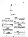
cated on the template. The mounting dimen-
sions are shown on Figure 2-l . .
Drill holes in the mounting surface of a proper
size to accommodate the hardware being used.
If necessary, prepare these holes with inserts,
anchors or other attachment devices as dic-
tated by the type of mounting surface.
Attach the KSU to the mounting surface with
four (4) screws installed through the KSU
mounting flange and into the mounting surface
holes. Note that the flange holes are elongated
with an enlargement at one end. This feature
allows the mounting screws to be partially in-
stalled in the mounting surface before the
cabinets are hung on them.
Place the individual telephone stations as
desired and in keeping with accepted industry
and office standards. Currently produced 8
tine Keysets can be wall mounted if necessary
as they are
desk/wall
reversible. Currently
produced keyset models include:
l
3508~xx-xx-OOOM
l
3508~xx-xx-035M
l
3598~xx-xx-000s
l
6414+x
l
6414L-xx
l
6414Sxx
_
_
._
_
Refer to Chapter 4, Maintenance, for instructions in
preparing a desk/wall reversible station for wall mount-
ing.
Any previously produced keysets which may currently
still be in service can also be wall mounted if necessary.
Use a wall mounting bracket (part number 701032-056)
for this purpose.

Installation
IMI 66-031
I
I
I
0-
I
-t-
19.22
INCHES
1
l----sk~
0-
---o--
l
I
Figure 2-1. Mounting
DimenSlOnS
SYSTEM WIRING
System cabling may be routed concealed or visible as
the installation location requires, Good engineering
practices must be observed
and
all applicable building
codes must be adhered to.
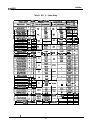
Table 2-l and Figures 2-2
through 2-4 illustrate the system wiring and connection
points for the key system.
AC Power Connection
The AC power is applied to the system by connecting
the AC power cord to the standard (NEMA
515R)
electrical outlet which supplies the dedicated 117VAC
@ 15 AMP electrical power.
The following precautions should be taken to help
prevent damage to the system which could be caused
by an electrical over-voltage condition.
l
Do not connect the ACpower cord until the in-
stallation has been checked per the SYSTEM
CHECKOUT instructions given at the end of
this Chapter.
l
Employ a dedicated lVL!AC
15
AMP circuit,
with a third-wire ground, supplied to a stand-
ard (NEMA
5-15R)
electrical outlet for the
AC
power connection.
l
A plug-in, powerline surge protectof should be
installed between the KSUpowercordand the
AC power eiectrkai outlet.
Line Connection
The KSU interface connections for the COlPBX lines
are individual
mdular
jacks. Wiring between the KSU
connectors and the demarcation point connectors is via
standard modular line cord.
The
maximum allowed
tip/ring loop resistance is 1900 ohms from the KSU
modular jack to the CO/PBX equipment.
To help Insure that foreign voltages, which could
appear on the CO lines, do not damage the system,
verify that gas discharge tubes orsimiiarprotection
devices are installed, and properly grounded, in all
connected CO lines.
Statlon Connection
Connections between the KSU and the stations are typi-
cally via type 66M-xx connector blocks which are cable
connected to the KSU
50-pin
male connectors. The
maximum distance allowed from the KSU to a station is
1500 feet using #I24 gauge, twisted-pair cable.
.
If spare conductors exist in the cables that are run be-
tween the KSU 66M-xx connector block and the station
f

IMI 66-031
Installation
jacks, it is a good practice to connect them to earth
ground. Doing this may help prevent them from induc-
ing radio frequency and/or AC interference into the
SYS-
tern
The polarity between the individual wires in a par-
ticular voice or data pair is not critical; however do
not connect the voice circuits to the data
CirCuits.
Cable
CIips
Each cabinet-mounted
50-pin
male connector is
equipped with a retaining clip. This clip is designed to
secure the matted connection once it is made. The clip
does this by snapping into a slot on the cable-mounted
connector when it is pressed together with the cabinet-
mounted connector. This retaining clip must be pulled
back slightly to un-snap it before the connectors can be
separated.
DSSIBLF
Console Connection
The optional DSS/BLF console may be installed at any
station port to work in conjunction with a companion sta-
tion connected to the adjacent port (e.g.; port 10 for sta-
tion and port 11 for console).
The installed distance limit between the KSU and a con-
sole is the same as that specified for a regular station.
Connect all four wires (voice pair and data pair) of the
console cable to the station connector block.
The voice pair connections of the console can be used
simultaneously to enable a PA port function. Refer to
the paragraph in this chapter headed Area Paging In-
terface
-
Station PA Port. Per that discussion, wire a PA
amplifier input to the DSS/BLF console voice-pair at the
connector block clip terminals. Use an audio matching
transformer, as discussed in the referenced paragraph
and Figure 2-3, to provide isolation. If an enable signal
is required with the particular PAequipment being used,
the console and PA equipment connections are limited
to station ports 23 and 25.
The DSS/BLF console port must be programmed as a
DSSIBLF port (see Chapter 3 for programming details)
before console operation can take place. The console
port must be also programmed as a PA port if a PA
amplifier has been connected to the voice pair as part
of the system.
Busy Lamp Field Stations
An optional keyset is available which is equipped with
a 14 station Busy Lamp Field (BLF). Up to eight BLF
stations can be connected to the system. A BLF station
f
can be connected to any odd or even station port in the
system per the following guidelines.
The installed distance between the KSU and the
BLF station must be limited to 1000 feet or less.
The data-line paired station port cannot be used as
a BLF station connection or as a regular station
connection. Data-line pairing is: 1 O-l 1,12-13,
14
15,16-17,18-19,20-21,22-23, and 24-25.
The overload paired station port cannot be used as
a BLF station connection but can be used as a
regular station connection. Overload pairing is: 1
O-
12, 1%13,14-16,15-17, 18-20,19-21,22-24, and
23-25.
A port, paired in either manner with a BLF station,
can be used as a PA port if desired.
Power Failure Station Connection
The system provides a tip and ring-pair connected to
line 1 as an emergency power failure circuit. This power
failure pair is available at clip terminals on connector
block J-l as detailed on Table 2-l and Figure 2-4. A
power failure pair is only active durfng a commercial
AC
power failure. An industry standard, single-line
telephone, such as a Comdial model 2500-xx, can be
connected to a power failure pair and used to provide
communications capability until the AC power to the
system is restored.
A-Lead Control Device Connection
The KSU can detect an A-lead
(A
and Al) control sig-
nal when it is applied to lines 7 and 8. An A-lead con-
trol device can be bridge-connected to these lines via
clip terminals on connector block J-2 as detailed on
Table 2-1 and Figure 2-4.
Data Device Connection
When a serial data printer is used for SMDR and COS
printout, connect it to clip terminals on connector block
J-l as detailed on Table 2-1 and Figure 2-4.
The distance between the device and the KSU can be
up to 500 feet in a quiet electrical environment.
Shielded cable may be required at some sites for long
runs. For longer distances, a limited distance modem
must be used to relay the data communications be-
tween the KSU and the data device.
When preparing a cable for connection to a data device,
refer to the manufacturer’s manual for the equipment
being interfaced, and make the following wiring connec-
tions:
*
Wire the KSU RD line (data from printerto wmmon
equipment) to the device TD (transmit data) output
pin,
2-3

Installation
IMl66-@31
Wire the KSU TD (data to device from KSU) pin to
the device RD (receive data) pin.
Wire the KSU SG (signal ground) pin to the device
SG (signal ground) pin.
Wire the KSU CTS (clear-to-send status from
device to KSU) pin to the device FITS (request-to-
send) output pin.
NOTE: The
KSUrequires
a
positive
voltage,
wtth
respect to signal ground, in order to send data.
If required, wire the KSU
FITS
(request-to-send
status signal from the KSU to the device) pin to the
device DSR (data-set-ready) input pin.
If required, wire the KSU PG (protective ground)
tine(s) to the device protective ground pin(s).
Data Format
Configure the data device to match the following data
format and to receive data at the baud rate that is set
by COS programming.
l
7-bit data with 2 stop bits and no panty
-
fixed
l
Baud rate of 110 baud (defautt)
-
can be changed
to 300 baud through class of service programming.
System Grounding
It is required that a grounding wire, separate from the
three wire AC line cord, be used. A ground stud is to-
cated on the KSU for this purpose.
wire
#lO
or#l2,
in-
sulated, solid copper wire between the ground stud and
a reliable earth ground such as a metal cold water pipe
or a building frame ground.
Common
Audtble
and Auxiliary Station interface
Two sets of relay closure drycontact points are avail-
able at the J-l station connector block.
l
One set (J-l connections) provides a dry-contact
closure whenever any of the
TELCOIPBX
lines,
connected to the KSU, ring.
l
The other set provides a dry-contact closure when-
ever system station 17 rings.
These contact closures track the ringing pattern in both
cases. The contacts are closed during the ringing
period and are
open
during the silent perfod.
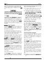
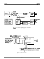
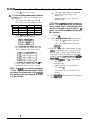
A typical connection is illustrated in Figure 2-2. Refer
to the paragraph headed Area Paging Interface for a
discussion for using these terminals in the
attemate
paging function.
Do not exceed a
I
amp at 24 volts
(.5amp
at 48 volts)
load on these control terminals.
If the load
requlre-
ments exceed thls
Ilmlt,
connect the load through
an external slave relay.
DO NOT CONNECT THESE
CONTROL TERMINALS DIRECTLY TO THE 117VAC
LINE.
24

IMI 66-031
Installation
Area
Paging
Interface
-
Station PA Port
A station port can be configured by class of service
programming to be a PA port. As a PA port, it can be
used to couple a station voice path to an external device
(see Chapter 3 for programming details).
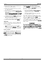
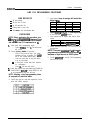
The audio input of an external paging amplifier can
be connected to the audio pair of the station port as
illustrated in Figure 2-3.
The audio input connection must be isolated with a
600 ohm to 600 ohm audio matching transformer.
Terminate the audio input of the paging amplifier
with a 620 ohm (nominal value) resistor.
If station port 23 is programmed as a PA port, the
Common Audible contact points are automatically
reconfigured as PA enable terminals. The contact
closure now occurs when PA station 23 is dialed.
The normal common audible function, as discussed
previously, is disabled as long as station 23 is a PA
station.
If station port 25 is programmed as a PA port, the
Auxiliary Station Interface (station 17 audible) con-
tact points are automatically reconfigured as PA
enable terminals. The contact closure now occurs
when PA station 25 is dialed. The normal auxiliary
station interface function, as discussed previously,
is disabled as long as station 25 is a PA station.
Area Paging Interface - Llne Port
A fine port can be configured by COS programming to
be an AUXILIARY port. As an AUXILIARY port, it can
be used to couple a station voice path to an external
device. This is done from any station with that tine ap-
pearance by pressing the proper line key to select the
AUXILIARY port.
DTMF tones or dial pulses can be
dialed through the AUXILIARY port as needed.
l
The audio input of an external paging amplifier can
be connected to the tip and ring leads of the line
Poe*
l
The audio input connection must be isolated with a
600 ohm to 600 ohm audio matching transformer.
Terminate the audio input of the paging amplifier
with a 620 ohm (nominal value) resistor.
A DTMF tone select, zone-paging amplifier can be
employed if desired. If used, the zone-select code must
be dialed after the AUXILIARY port line select key is
pressed.
Musk On Hold
If music on hold is to be part of the system, connect a
KX registered music source to the KSU input jack
(phono jack) provided for this purpose. The impedance
of this input is approximately 500 ohms. Level adjust-
ment of the music source may be necessary. This may
be done during system checkout.
f
2-5

Installation
MI 66-031
l----1
CLIP TERM .
-I-
OUTPUT AS
LOW
24V@
0.4A
MAX
REOUIRED
BY
RELAY
COIL
VpOokZE
SUPPLY
AC
--
-
VOLTAGE CLAMPING DIODE
RECOMMENDED
v
;g
:bXlNPUt
.
SIGNALLING
0
0
Flgure
2-2. External Signalling-Typical Connection.
600~
TO
SOOn(
1:1)
AUDIO
TRANSFORMi%
TO KSU STATION
PORT 23 OR 25 IF
ENABLE IS REQUIRED
OR TO ANY UNUSED
STATION PORT IF
ENABLE IS
NOT REQUIRED.
uus
62On
A SYSTEM
-0
AUDIO
INPUT
4
ENABLE INPUT
QQ
TO KSU EXTERNAL CONTROL CONNECTION
POlNTS
ON
66WXX
CONNECTOR BLOCK.
l CLIPS 45
&
46 FOR STATION PORT 23 PA ENABLE
l CLIPS 47
&
48 FOR STATION PORT 25 PA ENABLE
Figure 2-3. PA Connections.
t
2-6

IMI 66-031
Installation
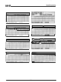
Table 2-l.
KSU To
Station Wring.
I
----.----a-
l
.“m
I
---.I.-
Y-L.
I
_-_.
STATION
GREEN-WHITB
GREEN 5
RED
6
YEUDW 7
!
BLACK 6
h
ers~mzu
.
1
Is-.--
wmllt-JUIt
SLATE-WHITE
6
5
RED-BLUE
31
BLUE-RED
6
6
RED-ORANGE
32
.
ORANGE-RED
7 7
RED-GREEN
,
GREEN-RED
RFCLRR
VOICE
PAIR
DATA
PAIR
VU&C
“n==-
1
22 .
PAIR
RED
1;
xt
YEUOW 11
BLACK 12
CREEP
l *
*
_..--
-
-_--
BROW..-..,,
.,
1
14
1
_
_____
RED-SLATE
1
__
t
65
nhTA
1
24
1
_
_--
DATA
1
YEUDW
n
10
ii
I
-n.-
SLATE-RED
1
DAID
:K-BLUE
36
i
15
16
ORANGE-YELLOW1
YELLOW-GREEN ,6
43
GREEN-YELLOW
18
r-.8x
YELLOW-BROWN.
19
U
BROWN-YELLOW
19
19
Y!EE
I
YELLOW-SLATE
.
26
45
I
DATA
SLATE-YELLOW
20
llilrn
,
VII31
FT-RL
IIF
A6
SPARE
I
“rn”b
I
IYELLOW
1
29
I
-
I
=+UCK
I
I I
I
-.-
I
1
9I
1
48
1
COMM.
1
CONTACT
1
t--U
j
TIP GREEN
45
GREEN-VIOLET
I-n”-
TELCO
I-
RI
ING
RED
46
LINE6
f
A YELLOW
47
Al
BLACK
46
1 I
I
I
--~~--~--
I
VIOLET-SIATE
1
3s
1
59
)
POWER
1
TIP
CDARF
GREEN
49
SLATE-VIC RED
56
)LET
1
--
I 25
1
FAIL
1
RING
1
“’
-‘=-
:
2-7


Installation
CHECKOUT
Check the KSU and telephone installation for proper
operation by performing the following actions.
Resistance
Check
Make the following resistance measurements at the Sta-
tion connector blocks under the following conditions.
l
AC power cord disconnected from electrical outlet.
l
KSU connected to station connector blocks.
l
Stationswired, and wiring punched downon blocks.
l
Bridging clips removed from blocks to isolate sta-
tions from common equipment.
1.
Measure the resistance of each installed sta-
tion
and wiring from the station side of the con-
nector blocks. Resistance values will vary with
cable length and station type but should be
within the following limits. Readings which are
outside of these limits indicate a possible wiring
or station problem.
2.
VOICE PAIR:
(40 OHMS MIN.-150 OHMS MAX.)
DATAPAIR:
(0.3 OHMS MIN.-100 OHMS MAX.)
Measure the resistance of the KSU and cables
from the KSU side of the station connector
blocks. Resistance values should be within the
following limits.
MEASURFD PAIR
VOICE PAIR
DATA PAIR
Voltage
Check
MEASURED KSU
RFSISTANCF IN OHMS
40-50
0.3
-
0.5
Make the following voltage measurements at the station
connector blocks under the following conditions:
*
Bridging clips installed
l
AC power connected to the common equipment
Measure the voltage across one voice line and one data
line and then across the other voice line and the other
data line for each even and odd station. The measured
voltage must be as follows:
UNIT
UNDtR
66Mxx BLOCK
Mt
I
tH
LtAD MEASURtD
TEST
CONNECTION POLARITY VOLTAGE
TYPICAL EVEN
Voice 1
I
(+I
STATlON
Data 3
I-1
.
+33+&5vDc
I
(Repeat for
each even sta.)
TYPICAL ODD
STATION
(Repeat for
each odd
sta.)
voice2
Data 4
Voice
5
Data
7
Voice 6
Data 8
(+I
_
t-1
+33+1-SVDC
(+I
I-) -33
+I-
5
VDC
(ii
t-1
-33+/-5VDc
Variant readings can indicate a possible wiring, station,
or common equipment problem.
General Check
1.
2.
3.
Check the red light emitting diode (LED) sys-
tem status indicator.
Be sure that it is on steady. If it is off or flash-
ing, disconnect and reconnect the AC power
plug. If the indicator is still not on steady, refer
to the Failure Analysis Flow Chart found in
Chapter 4.
Refer to the station User’s Guide for operating
information.
Perform a general operational test of the sys-
tem by exercising the systemfeaturesfrom sta-
tion port 10 or 11. Operational parameters are
per the system default conditions as detailed in
Chapter 3 until COS programming is per-
formed.
Once the basic system is verified as operation-
al, perform the COS programming.
:
2-9

IMI 66-031 System Programming
CHAPTER 3
SYSTEM PROGRAMMING
GENERAL INFORMATION
Class Of Service (COS) programming consists of
setting the Class Of Service (COS) operating con-
ditions. COS programming is divided into the fol-
lowing three major categories: System COS, tine
COS, and Station COS.
All COS programming commands must originate at
station 10. No COS programming commands can
be accepted from any other station connected to the
system. COS programming causes station 10 to
default to a square condition (line select key 1
selects line
1,
key 2 selects line 2, etc.). It is recom-
mended that station 10 always remain in a square
conditionto avoid possible programming confusion.
COS programming does not require that a sequen-
tial process be followed once the base level
program entry mode has been established except
where noted herein.
The system defaults to preset characteristics when
it is initially powered up or whenever programmed
to do so. If the default characteristics, or any other
previously set characteristics, are satisfactory,
those portions of the programming sequence may
be omitted.
Prior to taking any programming action, record the
system, line and station COS conditions on Table
3-1,3-2, and 3-3 (included at the end of this chap-
ter). Also, record all toll restdction requirements on
Table 3-4.
THE PROGRAMMING STEPS MUST BE PER-
FORMED WITH LESS THAN 17 SECONDS OF
DELAY TIME BETWEEN KEYSTROKE OPERA-
TIONS. A delay of longer that 17 seconds causes
the KSU programming mode to time out.
Flgure 3-3 found at the end of this chapter provides
a quick-reference flow diagram of the class of ser-
vice programming requirements.
Programming is the same for both the model 0616X
and 0816X key systems. The only difference be-
tween these two models is the number of lines
which each serves (six or eight).
BASE LEVEL PROGRAM ENTRY MODE
The first step in a COS programming sequence is to
enter the base level programming mode. Once in
this mode, COS can be set as desired.
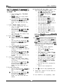
1. Press ITCM. The dial tone will sound.
2. Press the following keys in sequence:
8
7 4 6.
The dial tone stops and a tone burst sounds to in-
:
3.
c&ate that the base level programming mode is
entered.
Press
*.
The dial tone will return as a confirma-
tion that the base level mode is active.
CLASS OF SERVICE DEFAULT
The system can be defaulted to a standard class of
service per the following procedure.
1. Press
ITCM.
2.
Press the following keys:
*
7 4 6
*
# 0
*
3. Press MONITOR.
The following system default conditions are set:
-
-
-
-
-
-
-
-
-
-
-
-
-
-
-
-
-
-
-
-
-
All lines are DTMF
Voice signalling attempted first when inter-
com call is made
1
sec. pause time
2 sec. dial tone recall time
30 sec. recall from hold
All lines private
All lines are CO lines
No toll restriction set
300 msec. held call abandon time
No ringing line preference enabled
No prtme line is chosen
DSSBLF
port is disabled
PA port is disabled
No delayed ringing enabled
No access denied
No origination denied
No automatic privacy released
Day and night ringing patterns set as follows:
-
station 10,
4
7, and 24 all lines
System-wide, all call paging in zone D
Printer port set for 110 baud data rate
Line select keys l-n selects lines l-n
(squared pairing)
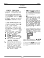
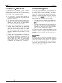
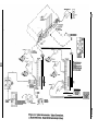
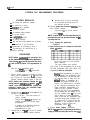
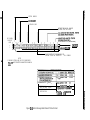
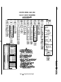
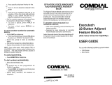
PROGRAMMING KEYS
Figure
3-l
illustrates the programming keys called
out in the following procedures.

IMI 66-031 System Programming
Al -
A2-
A3
-
A4
-
A5
-
A6 -
A7 -
B5
-
84
-
Bl
-
1
0-o
010
0
El3
0
0
0
0 0
0
0
O-0
I
4’
,
Figure 3-l. Programming Key Layout
1
A8
A9
A10
All
A12
-
Ad3
-
Al4
-
B6
-
87
-
88
-
83
-
B2
:
3-2

IMl66-031 System Programming
-
-
-
-
-
-
-
-
-
-
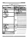
SYSTEM.COS PROGRAMMING PROCEDURE
SYSTEM DEFAULTS
All lines are DTMF
Voice signalling attempted first when inter-
com call is made
1 sec. pause time
2 sec. dial tone recall time
30 sec. recall from hold
All lines prfvate
All lines are CO lines
No toll restriction set
Printer port set for 110 baud data rate
2 sec. automatic pause insertion wait time
PROCEDURE
NOTE: Before performing this procedure, turn
to the System COS Programming Reference
Chart (Table
3-l),
locatedat the end of this chap
ter,
and record all system COS requirements on
it.
1. Press
tTCM
++
7 4 6
+K
(base level entry)
2.
Select the
PULSE/TONE
or TONE ONLY dialing
system default characteristics.
l
Press #. Dial tone will stop.
l
Press 0 to select
TONE ONLY.
m
l
Press 1 to
sgct
PULSE/TONE.
l
Press
*.
Dial tone will return.
NOTE: In addition to setting the dialing mode,
the above action defaults the system, line and
station COS.
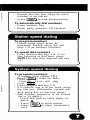
3. Select Intercom
slgnalling
first performed
when intercom call is placed.
l
Press Al3 for tone signalling.
-or-
.
Press Al4 for voice signalling.
l Press
*.
4.
Select time interval for programmed pause.
l
Press 4. Dial tone will stop.
l
Press key to select time interval per
chart. Tone burst confirms selection.
l
Press
f.
Dial tone will sound.
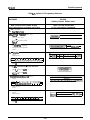
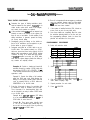
5. Select pulse dial operatlng characteristics.
l
Press 5. Dial tone will stop.
l
Press keypad key to select operating
characteristic per chart. Tone burst con-
firms selection.
\
KEY PULSES PER SECOND
I
BREAK/MAKE
RATIO
1
10
PPS
I
6W40
2
20
PPS
6W40
0
Press the % key. Dial tone will sound.
6.
Select
flash/dial tone recall time
interval.
l
Press 6. Dial tone will stop.
l
Press keypad key to select time interval
.from chart.
l
Press
*.
Dial tone will sound.
7.
Select
hold
recall
time
interval.
l
Press 7. Dial tone will stop.
l
Press keypad key to select hold recall in-
terval from chart.
NOTE: The
Q
program selection makes
It
pos-
sible for an exclusive hold condition, when set
at a station, to place a line on a pennanent hold
thaf cannot be released at any other station.
:
3-3

System Program-
~~166-031
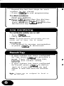
8.
l
Press
*.
Dial tone will sound.
Select
toll restriction table entries. Refer to
programming table (Table 3-4) to preselect entry
requirements.
l
Select table with memory key. The dial
tone will stop when the selection is made.
1 KEY 1 TABLE 1 KEY I TABLE
1
AlAl
11
A5A5 55
A2A2 22 A6A6
66
A3A3 33 A7A7
77
A4A4 44 A8A8
88
l
Select
mode of table
with keypad key.
Tone burst conforms selection.
l
Select
entry line on table
with memory
key. Action clears any current entry and
causes continuous busy tone to sound.
l
Dial
number for entry line. Press
%
key
to enter “match anything” digit. Tone
burst sounds after each key is pressed.
NOTE: An entry line can contain a maximum of
16 digits.
When the maximum number of digits
are entered, the system sounds a fast
ringback
tone, and steps to the next entrypoint on
a
table
or to the next table.
.*
If less than sixteen digits are entered on
line, select next entry location with
memory key.
l
Repeat procedure for each desired toll
restriction table.
NOTE: Select an
et&y
line even if no input is re-
quired.
This action insures that any previous
entry is cleared. Select a table and then select
each line in the table to clear the table of
ail
entries.
Do not dial any numbers after the entry
line selections.
l Press
f.
9.
Program
data speed baud rate
for printer port.
l
Press 3 to set data speed of 300 baud.
-or-
*
Press 0 to set data speed of 110 baud
(defautt).
l Press
*.
10. When the system stores a dialed number for later
redial, it automatically stores a pause each time
the user waits a period of time between digits.
(The length of the stored pause was programmed
in step 4.) To program
length of time to
wait
be-
tween’digits
is inserted, proceed as follows:
l
Press
ITCM
+K
7 4 6
*
to enter program-
ming mode.
l Press RECALL..
l
Press keypad key 1 to set wait time to
750 milliseconds.
-or-
*
Press keypad key 2 to set wait time to 2
seconds.
l Press
*.
11. Press
MONtTOR
to exit system COS program-
ming mode.
.
:
3-4

IMI
66-031
System Programming
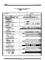
LINE COS PROGRAMMING PROCEDURE
-
-
-
-
-
LINE DEFAULTS
All lines private
All lines are CO lines
No toll restriction Set
Dialing mode is tone only
300
msec.
held call abandon time
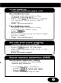
5.
6.
PROCEDURE
NOTE: Before performing this procedure, turn
fo
the Line COS
Programming
Reference Chart
(Table
3-2),
located at the end of this chapter,
and record all line COS requirements on it.
7.
1. Enter base level programming mode:
l Press
ITCM
+K
7 4 6
+K.
The dial tone
8.
will sound.
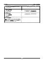
Press keypad key to restore after hold is aban-
doned.
KEY TIME INTERVAL
8
60
MSEC.
9
300 MSEC.
(MFAULT)
Repeat procedure from step 3 for next fine to be
programmed.
2.
Choose
privacy
status
of each line.
NOTE: There are a
maxlmum
of
six
lines
to
be
l
Press 8. Dial tone will stop. This action
programmed on a model 0616X system and a
initializes all lines as private. This condi-
maximum of eight lines on an 0816X system-
tion is also system default value.
9.
l
Press line select key of each line which
Press& MONtTOR to exit line COS programming.
is to be non-private.
Dial tone will sound.
Press memory
keys to assign toll restriction
tables to
Ilne.
KEY
TABLE
KEY
TABLE .
Al
1
A6 6
A2
2
A6
6
A3 3
A7 7
A4
4 A8 8
Specify dialing mode per
chart
with keypad key.
A tone burst will confinn selection.
-
A tone burst sounds after each selection
for confirmation.
l
Press
%.
Dial tone will sound.
3.
Press tine select key (program keys Bl-B6 for
model 0616X or
Bl
-B8 for model 0816X) for line
to be programmed. Dial tone will stop.
NOTE: Selecting a line forprogramming clears
all assigned toll restriction tables.
4. Specify line type per chart with keypad key. Atone
burst will confirm selection.
3-5

IMI 66-031
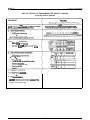
STATION COS PROGRAMMING PROCEDURE
System Programming
STATION DEFAULTS
r
No ringing line preference enabled
-
No prime line is chosen
-
DSS/BLF port is disabled
-
PA port is disabled
-
No delayed ringing enabled
-
No access denied
-
No
orfgination
denied
-
No privacy released
-
Day and night ringing patterns set as follows:
-
station 10, 17, and 24 all lines
-
System-wide, all call paging in zone D
-
tine select keys
1
-n selects lines
1
-n
(squared pairing)
PROCEDURE
NOTE: Before
peffotming
this procedure, turn
to the Station COS Programming Reference
Chart (Table 3-3), located at the end of this chap-
ter, and record ail station COS requirements on
it.
1.
Enter the base programming mode:
l
Press ITCM
+#
7 4 6
+#.
Dial tone will
sound.
2.
Press a two-key sequence on keypad to choose
station port for programming (i. e.,to choose sta-
tion 11 press 11). Tone burst sounds to confirm
selection. Improper selection results in dial tone.
NOTE: Station port selection defaults the foi-
lowing features:
DSS/BLFport
enable,
,PA
port
enable, prime line selection, and ringing line
preference enable. Pius, toil restriction table
assignments are disabled.
3. Configure port as DSS/BLF console
port
(if con-
sole port is required).
.
Press RECALL. Tone burst sounds to
confirm selection.
l
Skip this step if DSS/BLF console is not
installed at station port currently being
programmed.
l
If enabled, do not proceed beyond this
step unless port is also to be
programmed as PA port.
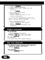
4.
Configure port as
PA
port
(if PA port is desired).
*
Press 9. Tone burst confirms selection.
:
a
Skip this step if PA port is not desired.
l
Do not proceed beyond this step if PA
port selection
is
made.
5. Choose prime line or prime
fntercom.
Tone
burst confirms selection.
l
Press tine select key for line desired.
-or-
* Press
ITCM.
NOTE: if more than one iine selection key is
pressed, the last one pressed selects the
ac-
cep ted prime line.
6. Enable
ringing line preference.
l Press 1.
7. Press memory keys to assign toll restriction
tables to station.
l
At this point, there are no toll restriction
tables assigned.
l
Tone burst confirms each selection.
Skip to step 16 after programming the toll restric-
tion table assignments unless other station COS
programming
must be performed.
l
Durfng initial programming of a station, it
is recommended that programming steps
8-14 be performed in the order that they
are presented below. In steps 8-14, the
defautt condition is automatically set
whenever the program selection key is
pressed. This default value is overridden
by the subsequent programming action.
l
During subsequent reprogramming of a
station, any step, controlling a feature
that does not need to be reprogrammed,
can be skipped over thus leaving the cur-
rent COS condition intact. It is not neces-
sary to return to the base programming
mode to shift from one programming step
to another except when performing step
15. Program step 15, which sets the line
appearance to key assignment, must be
followed by a return to base level
programming (press
*).
8. Program
direct ringing
assignments.
NOTE: A
line
may be programmed for direct
ringing or delayed ringing but not for both ring-
3-6

IMI 66-031
System Programming
trig
features.
If
dtrect rtngtng
Is
setected after
delayed rtngtng
Is
selected, delayed rtngtng wttt
be disabled.
Press 2 for direct tinging.
Tone burst
sounds to confirm.
DefauQ
condition of no ringing enabled
now set on all iines.
Press line select
key
(program
keys
Bl-
B6 for 0616X and
Bl
-B8 for 0816X)
for
each line on which direct ringing
is
desired. Tone sounds after each selec-
tion.
9. Program
delayed ringing
assignments.
l
Press 3 for delayed tinging. Tone burst
sounds to confirm.
l
Press Iine select key (program keys
Bl-
B6 for 0616X and
Bl
-B8 for 0816X) for
each line on which delayed n’nging is
desired.
l
Tone sounds after each selection. Delay
time is 15 seconds.
10. Choose
access
denled
status.
0
Press 4. Tone burst sounds. Defauft
condition of access not denied set on all
lines.
l
Press line select key (program keys
Bl-
B6 for 0616X and
Bl
-B8 for 0816X) for
each line on which access is to be
denied.
l
Tone burst sounds after each selection.
11. Program
call origination denled
status.
l
Press 5. Tone burst sounds. Default
condition of call origination not denied set
on all lines.
l
Press line select key (program keys
Bl-
B6 for 0616X and
Bl
-B8 for 0816X) for
each line on which call origination is to
be denied. Tone burst sounds after each
selection.
12.
Set access to
privacy release.
l
Press 6. Tone burst sounds. Defauit
condition of no access to privacy release
set on all lines.
l
Press line select key (program keys
Bl-
B6 for 0616X and Bl -B8 for 0816X) for
each line on which access is to be
denied. Tone burst sounds after each
selection.
13. Set night ringing status.
l
Press 8. Tone burst sounds. Defauit con-
dition of no night ringing
will
be set on all
lines.
e
Press line select key (program keys
Bl-
B6 for 0616X and
Bl
-B8 for 0816X) for
each line on which night ringing is
desired. Tone burst sounds after each
selection.
14. Set all-call and zone paglng
capability. Default
value is all-call at all stations in system.
l
Press 1. Tone burst sounds. Clears sta-
tion from paging zones A, B,
and C.
l
Press ITCM to clear station from atl-catl
(if required).
l
To assign reception by zone,
l
Press line select key
1
(Bl)
for zone A
l
Press tine select key 2 (B2) for zone B
l
Press line select key 3 (B3).for zone
C.
l
Press line select key 4 (84) for all-call (if
it was previously cleared).
l
To enable origination by zone,
l
Press line select key 5 (B5) for zone A
.
Press line select key 6 (B6) for zone B
l
Press line select key 7 (B7) for zone C
l
Press line select key 8 (B8) for all-call (if
it was previously cleared).
NOTE:Step
ldmustbe
tmmedtapty fottowedby
a
return
to bass level.
15.
Set
llne
appearance to key assignment if cur-
rent settings are not correct. System default con-
figures line appearance to key assignment so that
line assignments are squared. A squared assigri-
ment has tines l-6 assigned to keys Bl-B6 for
model 0616X, and lines l-8 assigned to keys
Bl-
B8 for model 816X.
l
To re-assign line/key configuration,
l
Press 7. Tone burst sounds.
l
Press Gne key
(Bl-88).
Tone burst
sounds.
l
Press keypad key
for
number of line
(l-
6). Tone burst sounds.
l
Press next line key and keypad key com-
bination. Repeat for each line. All iine
select keys can be programmed to select
same tine if such a condition is desired.
l
To disable line select key and indicator
tight for any lines which are unassigned
to a particular station,
l
Press line select key for unassigned line.
l Press 9.
l
Repeat for each unassigned line.
16. Press % to return to base programming mode.
17. Repeat steps 1 through 16 for each station con-
nected to the system.
18. Press MONITOR to exit programming
mode.
Page is loading ...
Page is loading ...
Page is loading ...
Page is loading ...
Page is loading ...
Page is loading ...
Page is loading ...
Page is loading ...
Page is loading ...
Page is loading ...
Page is loading ...
Page is loading ...
Page is loading ...
Page is loading ...
Page is loading ...
Page is loading ...
Page is loading ...
Page is loading ...
Page is loading ...
Page is loading ...
Page is loading ...
Page is loading ...
Page is loading ...
Page is loading ...
Page is loading ...
Page is loading ...
Page is loading ...
Page is loading ...
Page is loading ...
Page is loading ...
Page is loading ...
Page is loading ...
-
 1
1
-
 2
2
-
 3
3
-
 4
4
-
 5
5
-
 6
6
-
 7
7
-
 8
8
-
 9
9
-
 10
10
-
 11
11
-
 12
12
-
 13
13
-
 14
14
-
 15
15
-
 16
16
-
 17
17
-
 18
18
-
 19
19
-
 20
20
-
 21
21
-
 22
22
-
 23
23
-
 24
24
-
 25
25
-
 26
26
-
 27
27
-
 28
28
-
 29
29
-
 30
30
-
 31
31
-
 32
32
-
 33
33
-
 34
34
-
 35
35
-
 36
36
-
 37
37
-
 38
38
-
 39
39
-
 40
40
-
 41
41
-
 42
42
-
 43
43
-
 44
44
-
 45
45
-
 46
46
-
 47
47
-
 48
48
-
 49
49
-
 50
50
-
 51
51
-
 52
52


Comdial ExecuTech 0616 Series User manual
- Category
- Door intercom systems
- Type
- User manual
- This manual is also suitable for
Ask a question and I''ll find the answer in the document
Finding information in a document is now easier with AI
Related papers
-
 Comdial Executech Single Line Telephone User manual
-
 Comdial K2264 User manual
-
 Comdial Solo II 5531S User manual
-
 Comdial SOLO II Users Manualde
-
 Comdial 1432 Series User manual
-
 Comdial DX-80 Installation & Maintenance Manual
-
 Comdial DX-80 Specification
-
 Comdial DX-80 Specification
-
Vertical Comdial DX-80 User manual
-
 Comdial Impression System Reference Manual


Other documents
-
Vodavi Starplus DHSE Technical Manual
-
-
-
LG-Ericsson iPECS-MG Hardware Description And Installation Manual
-
NEC Electra 616 User manual
-
-
Toshiba STRATA DK16 User manual
-
Toshiba DK 16 User manual
-
-