Code 3 3955 is a highly integrated siren amplifier, designed to be operated via user-supplied control switches and common microphone interface. Its standard features include:
- Industry-standard Wail and Yelp tones
- Electronic AIR HORN sound
- Instant-On activation with no separate ON/OFF switch
- Wail mode activation with a continuous positive signal applied to the Wail input
- Airhorn signal generation with a continuous positive signal applied to the Airhorn input
- Instant Public Address override of all siren functions when the motorcycle Push-to-Talk (PTT) key is pressed while the user-supplied common microphone interface is set to PA mode

Page 1 of 8
Model 3955 Motorcycle Siren
IMPORTANT! Read all instructions before installing and using. Installer: This manual must be delivered to the end user.
WARNING!
Sirens are an integral part of an eective audio/visual emergency warning system. However, sirens are only short range second-
ary warning devices. The use of a siren does not insure that all drivers can or will observe or react to an emergency warning signal,
particularly at long distances or when either vehicle is traveling at a high rate of speed. Sirens should only be used in a combination
with eective warning lights and never relied upon as a sole warning signal. Never take the right of way for granted. It is your responsibility to
be sure you can proceed safely before entering an intersection driving against trac, or responding at a high rate of speed.
The eectiveness of this warning device is highly dependent upon correct mounting and wiring. Read and follow the manufacturer’s instruc-
tions before installing this device. The vehicle operator should check the equipment daily to insure that all features of the device operate cor-
rectly.
To be eective, sirens must produce high sound levels that potentially can inict hearing damage. Installers should be warned to wear hearing
protection, clear bystanders from the area and not to operate the siren indoors during testing. Vehicle operators and occupants should assess
their exposure to siren noise and determine what steps, such as consultation with professionals or use of hearing protection should be imple-
mented to protect their hearing.
This equipment is intended for use by authorized personnel only. It is the user’s responsibility to understand and obey all laws regarding emer-
gency warning devices. The user should check all applicable city, state and federal laws and regulations. Code 3, Inc., assumes no liability for
any loss resulting from the use of this warning device.
Proper installation is vital to the performance of the siren and the safe operation of the emergency vehicle. It is important to recognize that
the operator of the emergency vehicle is under psychological and physiological stress caused by the emergency situation. The siren system
should be installed in such a manner as to: A) Not reduce the acoustical performance of the system, B) Limit as much as practical the noise
level in the passenger compartment of the vehicle, C) Place the controls within convenient reach of the operator so that he can operate the
system without losing eye contact with the roadway.
Emergency warning devices often require high electrical voltages and/or currents. Properly protect and use caution around live electrical con-
nections. Grounding or shorting of electrical connections can cause high current arcing, which can cause personal injury and/or severe vehicle
damage, including re.
PROPER INSTALLATION COMBINED WITH OPERATOR TRAINING IN THE PROPER USE OF EMERGENCY WARNING DEVICES IS ESSENTIAL TO
INSURE THE SAFETY OF EMERGENCY PERSONNEL AND THE PUBLIC.
Installation and Operation Instructions
WARNING!
Failure to install or use this product according to manufacturer’s recommendations may result in property damage, serious injury, and/
or death to those you are seeking to protect!
Do not install and/or operate this safety product unless you have read and understood the safety information
contained in this manual.
1. Proper installation combined with operator training in the use, care, and maintenance of emergency warning devices are essential to
ensure the safety of emergency personnel and the public.
2. Emergency warning devices often require high electrical voltages and/or currents. Exercise caution when working with live electrical
connections.
3. This product must be properly grounded. Inadequate grounding and/or shorting of electrical connections can cause high current arcing,
which can cause personal injury and/or severe vehicle damage, including re.
4. Proper placement and installation is vital to the performance of this warning device. Install this product so that output performance of
the system is maximized and the controls are placed within convenient reach of the operator so that they can operate the system without
losing eye contact with the roadway.
5. Do not install this product or route any wires in the deployment area of an air bag. Equipment mounted or located in an air bag
deployment area may reduce the eectiveness of the air bag or become a projectile that could cause serious personal injury or death.
Refer to the vehicle owner’s manual for the air bag deployment area. It is the responsibility of the user/operator to determine a suitable
mounting location ensuring the safety of all passengers inside the vehicle particularly avoiding areas of potential head impact.
6. It is the responsibility of the vehicle operator to ensure daily that all features of this product work correctly. In use, the vehicle operator
should ensure the projection of the warning signal is not blocked by vehicle components (i.e., open trunks or compartment doors),
people, vehicles or other obstructions.
7. The use of this or any other warning device does not ensure all drivers can or will observe or react to an emergency warning signal.
Never take the right-of-way for granted. It is the vehicle operator’s responsibility to be sure they can proceed safely before entering an
intersection, drive against trac, respond at a high rate of speed, or walk on or around trac lanes.
8. This equipment is intended for use by authorized personnel only. The user is responsible for understanding and obeying all laws
regarding emergency warning devices. Therefore, the user should check all applicable city, state, and federal laws and regulations. The
manufacturer assumes no liability for any loss resulting from the use of this warning device.

Page 2 of 8
Standard Features:
The Model 3955 siren is a highly integrated siren amplier designed to be operated via user supplied control switches and common micro-
phone interface. The following features are standard on Model 3955 sirens:
Siren Tones - Industry standard Wail and Yelp tones.
AIR HORN Tone - Electronic AIR HORN sound.
Instant-On - There is no “ ON/OFF “ switch. Selecting any siren function, or pressing the Push To Talk (PTT) switch on the user supplied
common microphone interface will activate the siren in the appropriate mode, assuming the siren is connected to a source of +12V and the
vehicle’s ignition switch is on.
Wail - A continuous positive signal applied to this input from a user supplied switch will cause to siren to activate in wail mode for as long as
the switch remains in the on position.
Airhorn - A continuous positive signal applied to this input from a user supplied switch will cause to siren to generate the Airhorn signal for as
long as the switch remains in the on position.
Instant Public Address - Public Address override of all siren functions when the motorcycle Push-to-Talk (PTT) key is pressed while the
user supplied common microphone interface is set to PA mode.
Automatic Short Circuit Protection - The siren will sense a short circuit on the speaker terminals and automatically go to standby until the
fault is removed. Once the fault is removed the siren will return to normal operation.
Unpacking & Pre-Installation:
After unpacking your 3955 series siren, carefully inspect the unit and associated parts for any damage that may have been caused in transit.
Report any damage to the carrier immediately.
Installation & Mounting:
The 3955 series siren is designed to be mounted to the optional equipment Amplier Mount, which can be obtained from the motorcycle manu-
facturer. A weatherproof connector is provided for connection to the controller harness provided with the motorcycle.
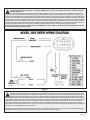
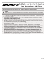
Connections (see Figure 1), motorcycle wiring harness.
Speaker - Connect to 100W (11 ohm) speaker leads.
+12V - Connect (16 AWG wire) to a positive +12 volt DC source. It is recommended that the user protect this wire with a 10
Amp fuse or circuit breaker located at the source.
- NEG (Ground) - Connect (16 AWG wire) to the negative terminal of the battery. This supplies ground (earth) to the siren.
AIRHORN - AIRHORN switch input . Circuit is congured to accept positive signals only.
WAIL - WAIL switch input . This switch should be a rocker type switch which maintains it’s position until switched OFF by
the user. This circuit is congured to accept positive signals only.
Microphone High - MIC HI signal from the user supplied, common microphone interface.
Microphone Low - MIC LO signal from the user supplied, common microphone interface.
PA PTT - PTT signal from the user supplied common microphone interface.
WARNING!
• Sirens produce loud sounds that may damage hearing
• Wear hearing protection when testing
• Use siren only for emergency response
• Roll up windows when siren is operating
• Avoid exposure to the siren sound outside of the vehicle
Specications:
Input Voltage: 10 to 16 VDC, negative ground (earth).
(Note: Operation above 15 VDC for an ex-
tended period of time may result in speaker
damage)
Oprating Current: 8A @ 13.6V with 11-ohm load ( 100W Spkr )
Standby Current: Ignition Switch input ON - Approx. 200 mA
Ignition switch input OFF- no stanby current
Cycle Rate: WAIL - 11 cycles/minute
YELP - 230 cycles/minute

Page 3 of 8
WARNING!
All devices should be mounted in accordance with the manufacturer’s instructions and securely fastened to vehicle elements of suf-
cient strength to withstand the forces applied to the device. Ease of operation and convenience to the operator should be the prime
consideration when mounting the siren and controls. Adjust the mounting angle to allow maximum operator visibility. Do not mount
the Hand-Held Controller in a location that will obstruct the drivers view. Mount the Hand-Held Controller mounting base in a convenient loca-
tion to allow the operator easy access. Devices should be mounted only in locations that conform to their SAE identication code as described
in SAE Standard J1849. For example, electronics designed for interior mounting should not be placed underhood, etc. Controls should be
placed within convenient reach* of the driver or if intended for two person operation the driver and/or passenger. In some vehicles, multiple
control switches and/or using methods such as “horn ring transfer” which utilizes the vehicle horn switch to toggle between siren tones may be
necessary for convenient operation from two positions.
*Convenient reach is dened as the ability of the operator of the siren system to manipulate the controls from their normal driving/riding posi-
tion without excessive movement away from the seat back or loss of eye contact with the roadway.
WARNING!
CONNECTION OF A 58 WATT SPEAKER TO THE SPKR TERMINAL WILL CAUSE THE SPEAKER TO BURN OUT, AND WILL VOID THE
SPEAKER WARRANTY!
The sound projecting opening should be pointed forward, parallel to the ground, and not obstructed or mued by structural com-
ponents of the vehicle. Concealed or under-hood mounting in some cases will result in a dramatic reduction in performance. To minimize this
reduction, mount the speaker so the sound emitted is projected directly forward and obstruction by vehicle components such as hoses, brack-
ets, grille, etc. is minimized. Electromechanical sirens and electronic siren speakers should be mounted as far from the occupants as possible
using acoustically insulated compartments and isolation mountings to minimize the transmission of sound into the vehicle. It may be helpful to
mount the device on the front bumper, engine cowl or fender; heavily insulate the passenger compartment; and operate the siren only with the
windows closed. Each of these approaches may cause signicant operational problems, including loss of siren performance from road slush,
increased likelihood of damage to the siren in minor collisions, and the inability to hear the sirens on other emergency vehicles.
APPROPRIATE TRAINING OF VEHICLE OPERATORS IS RECOMMENDED TO ALERT THEM TO THESE PROBLEMS AND MINIMIZE THE EFFECT
OF THESE PROBLEMS DURING OPERATIONS.
Figure 1

Page 4 of 8
WARNING!
Any electronic device may create or be aected by electromagnetic interference. After installation of any electronic device, operate all
equipment simultaneously to insure that operation is free of interference.
WARNING!
IMPORTANT WARNINGS TO USERS OF SIRENS: “Wail” and “Yelp” tones are in some cases (such as in the state of California) the
only recognized siren tones for calling for the right of way. Ancillary tones such as “Air Horn”, “Hi-Lo”, “Hyperyelp”, and
“Hyperlo” in some cases do not provide as high a sound pressure level. It is recommended that these tones be used in a secondary
mode to alert motorists to the presence of multiple emergency vehicles or to momentarily shift from the primary tone as an indication of the im-
minent presence of an emergency vehicle.
Operation:
WAIL, Switch - Produces the Wail tone continuously while this switch is in the ON position.
AIR HORN, Switch - Produces the Air Horn tone. If the siren is active in any mode, it reverts to that previous mode when the AIR HORN but-
ton is released.
PUBLIC ADDRESS (PA) - The PA portion of the siren is activated each time the motorcycle Push-to-Talk (PTT) button is pressed while the
user supplied common microphone interface is set to PA mode. While the PTT button is pressed, the PA function overrides any active siren
tone and routes the PA audio through the siren speaker. When the PTT button is released, the siren will automatically switch back to the siren
tone (if any) that was active when the button was pressed. Also refer to the Maximum P.A. Volume Adjustment procedure under the SET-UP
AND ADJUSTMENT section.
Maintenance:
Code 3 Model 3955 siren has been designed to provide trouble free service. In case of diculty, consult the Troubleshooting Guide located
on page 5 of this manual. Also check for shorted or open wires. The primary cause of short circuits has been found to be wires passing
through rewalls, roofs, etc. If further diculty persists, contact the factory for troubleshooting advice or return instructions. Code 3 maintains
a complete parts inventory and service facility at the factory and will repair or replace (at the
factory’s option) any unit found to be defective under normal use and in warranty. Any attempt to service a unit, by anyone other than a fac-
tory authorized technician, without the express written consent of the factory, will void the warranty. Units out of warranty can be repaired at
the factory for a nominal charge on either a at rate or parts and labor basis. Contact the factory for details and return instructions. Code 3 is
not liable for any incidental charges related to the repair or replacement of a unit unless otherwise agreed to in writing by the factory.
Set-Up and Adjustment:
The only adjustment necessary for the 3955 siren is the P.A. Volume Adjustment (accessible from the front of the unit) Make this adjustment
prior to securing the unit.
P.A. Volume Adjustment - This control is accessible by lifting the water resistant cover (located on the end of the siren opposite the connec-
tor) and sets the maximum level of the P.A. volume. While keying the microphone hold the microphone close to your lips and speak directly
into it in a normal voice and adjust the control until the P.A. volume out of the speaker is at the desired level and produces no feedback. Be
certain that the spring loaded water resistant cover is fully closed after you have completed this adjustment.

Page 5 of 8
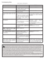
Troubleshooting Guide:
(Refer to Figure 1 Wiring Diagram)
PROBLEM PROBABLE CAUSE REMEDY
NO SIREN OUTPUT. A. SHORTED SPEAKER OR SPEAK-
ER WIRES. SIREN IN OVER CUR-
RENT PROTECTION MODE.
A. CHECK CONNECTIONS.
10A FUSE BLOWS. A. AMPLIFIER POWER WIRES RE-
VERSED POLARITY.
A. CHECK POLARITY.
NO OUTPUT FROM SPEAKER,
TONES HEARD INSIDE AMP MOD-
ULE.
A. SPEAKER NOT CONNECTED/
OPEN OR SHORTED SPEAKER WIR-
ING.
B. DEFECTIVE SPEAKER (NOTE:
SHORTED SPEAKER OR SPEAKER
WIRING WILL CAUSE SIREN TO
SHUT DOWN).
A. CHECK SPEAKER WIRING.
B. DISCONNECT SPEAKER, LISTEN
AT SIREN FOR TONES, REPLACE
SPEAKER.
SIREN TONES VOLUME TOO LOW
OR GARBLED.
A. LOW VOLTAGE TO SIREN AMPLI-
FIER.
B. HIGH RESISTANCE IN WIRING/
DEFECTIVE SPEAKER.
A. CHECK WIRING FOR BAD CON-
NECTIONS/ CHECK VEHICLE
CHARGING SYSTEM.
B. CHECK SPEAKER WIRING / RE-
PLACE SPEAKER.
HIGH RATE OF SPEAKER FAILURE. A. HIGH VOLTAGE TO SIREN.
B. 58 WATT SPEAKER CONNECTED
TO 100 WATT TAP. 58 WATT NOT
ALLOWED.
A. CHECK VEHICLE CHARGING
SYSTEM.
B. USE CORRECT SPEAKER.
SIREN CONTINUES UNTIL TONE
RAMPS DOWN AFTER MANUAL
BUTTON IS RELEASED.
NORMAL OPERATION.
P.A. VOLUME LOW OR NO P.A. AT
ALL. VOLUME CONTROL ADJUSTED
TO MAXIMUM.
A. REMOTE SWITCH (HORN RING)
WIRING TO REMOTE INPUT
SHORTING TO POSITIVE OR TO
GROUND (EARTH).
A. CHECK WIRING FOR ANY
SHORTING.
SIREN SOUNDS BY ITSELF. A. REMOTE SWITCH (HORN RING)
WIRING TO REMOTE INPUT SHORT-
ING TO POSITIVE OR TO GROUND
(EARTH).
A. CHECK WIRING FOR ANY SHORT-
ING.
SIREN RUNS PROPERLY BUT
SHUTS DOWN WHILE RUNNING,
THEN STARTS RUNNING AGAIN AF-
TER A FEW MINUTES
A. VEHICLE CIRCUIT BREAKERS
NOT RATED PROPERLY, AND ARE
OVERHEATING, OR ARE NOT FUNC-
TIONING PROPERLY
A. REFER TO SPECIFICATIONS
SECTION, PAGE 2. USE A BREAKER
WITH 1.25x THE AMPERAGE RATING
FOR THE WATTAGE BEING USED.
WARNING!
Larger wires and tight connections will provide longer service life for components. For high current wires it is highly recommended
that terminal blocks or soldered connections be used with shrink tubing to protect the connections. Do not use insulation displace-
ment connectors (e.g. 3M® ) Scotchlock type connectors). Route wiring using grommets and sealant when passing through compart-
ment walls. Minimize the number of splices to reduce voltage drop. High ambient temperatures (e.g. underhood) will signicantly reduce the
current carrying capacity of wires, fuses, and circuit breakers. Use “SXL” type wire in engine compartment. All wiring should conform to the
minimum wire size and other recommendations of the manufacturer and be protected from moving parts and hot surfaces. Looms, grommets,
cable ties, and similar installation hardware should be used to anchor and protect all wiring. Fuses or circuit breakers should be located as
close to the power takeo points as possible and properly sized to protect the wiring and devices. Particular attention should be paid to the lo-
cation and method of making electrical connections and splices to protect these points from corrosion and loss of conductivity. Ground (Earth)
terminations should only be made to substantial chassis components, preferably directly to the vehicle battery.
The user should install a circuit breaker sized to approximately 125% of the maximum Amp capacity in the supply line to protect against short
circuits. For example, a 30 Amp circuit breaker should carry a maximum of 24 Amps. DO NOT USE 1/4” DIAMETER GLASS FUSES AS THEY ARE
NOT SUITABLE FOR CONTINUOUS DUTY IN SIZES ABOVE 15 AMPS. Circuit breakers are very sensitive to high temperatures and will “false
trip” when mounted in hot environments or operated close to their capacity.

Page 6 of 8
NOTES:

Page 7 of 8
NOTES:

Page 8 of 8
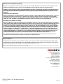
Manufacturer Limited Warranty Policy:
Manufacturer warrants that on the date of purchase this product will conform to Manufacturer’s specifications for this product (which are
available from the Manufacturer upon request). This Limited Warranty extends for Sixty (60) months from the date of purchase.
DAMAGE TO PARTS OR PRODUCTS RESULTING FROM TAMPERING, ACCIDENT, ABUSE, MISUSE, NEGLIGENCE, UNAPPROVED MODIFICA-
TIONS, FIRE OR OTHER HAZARD; IMPROPER INSTALLATION OR OPERATION; OR NOT BEING MAINTAINED IN ACCORDANCE WITH THE
MAINTENANCE PROCEDURES SET FORTH IN MANUFACTURER’S INSTALLATION AND OPERATING INSTRUCTIONS VOIDS THIS LIMITED
WARRANTY.
Exclusion of Other Warranties:
MANUFACTURER MAKES NO OTHER WARRANTIES, EXPRESS OR IMPLIED. THE IMPLIED WARRANTIES FOR MERCHANTABILITY, QUALITY
OR FITNESS FOR A PARTICULAR PURPOSE, OR ARISING FROM A COURSE OF DEALING, USAGE OR TRADE PRACTICE ARE HEREBY
EXCLUDED AND SHALL NOT APPLY TO THE PRODUCT AND ARE HEREBY DISCLAIMED, EXCEPT TO THE EXTENT PROHIBITED BY APPLI-
CABLE LAW. ORAL STATEMENTS OR REPRESENTATIONS ABOUT THE PRODUCT DO NOT CONSTITUTE WARRANTIES.
Remedies and Limitation of Liability:
MANUFACTURER’S SOLE LIABILITY AND BUYER’S EXCLUSIVE REMEDY IN CONTRACT, TORT (INCLUDING NEGLIGENCE), OR UNDER ANY
OTHER THEORY AGAINST MANUFACTURER REGARDING THE PRODUCT AND ITS USE SHALL BE, AT MANUFACTURER’S DISCRETION, THE
REPLACEMENT OR REPAIR OF THE PRODUCT, OR THE REFUND OF THE PURCHASE PRICE PAID BY BUYER FOR NON-CONFORMING
PRODUCT. IN NO EVENT SHALL MANUFACTURER’S LIABILITY ARISING OUT OF THIS LIMITED WARRANTY OR ANY OTHER CLAIM RELAT-
ED TO THE MANUFACTURER’S PRODUCTS EXCEED THE AMOUNT PAID FOR THE PRODUCT BY BUYER AT THE TIME OF THE ORIGINAL
PURCHASE. IN NO EVENT SHALL MANUFACTURER BE LIABLE FOR LOST PROFITS, THE COST OF SUBSTITUTE EQUIPMENT OR LABOR,
PROPERTY DAMAGE, OR OTHER SPECIAL, CONSEQUENTIAL, OR INCIDENTAL DAMAGES BASED UPON ANY CLAIM FOR BREACH OF
CONTRACT, IMPROPER INSTALLATION, NEGLIGENCE, OR OTHER CLAIM, EVEN IF MANUFACTURER OR A MANUFACTURER’S REPRESEN-
TATIVE HAS BEEN ADVISED OF THE POSSIBILITY OF SUCH DAMAGES. MANUFACTURER SHALL HAVE NO FURTHER OBLIGATION OR
LIABILITY WITH RESPECT TO THE PRODUCT OR ITS SALE, OPERATION AND USE, AND MANUFACTURER NEITHER ASSUMES NOR
AUTHORIZES THE ASSUMPTION OF ANY OTHER OBLIGATION OR LIABILITY IN CONNECTION WITH SUCH PRODUCT.
This Limited Warranty defines specific legal rights. You may have other legal rights which vary from jurisdiction to jurisdiction. Some
jurisdictions do not allow the exclusion or limitation of incidental or consequential damages.
Product Returns:
If a product must be returned for repair or replacement*, please contact our factory to obtain a Return Goods Authorization Number (RGA
number) before you ship the product to Code 3®, Inc. Write the RGA number clearly on the package near the mailing label. Be sure you use
sufficient packing materials to avoid damage to the product being returned while in transit.
*Code 3®, Inc. reserves the right to repair or replace at its discretion. Code 3®, Inc. assumes no responsibility or liability for expenses incurred for the removal and /or reinstallation of products requiring service and/or repair.; nor for the packaging,
handling, and shipping: nor for the handling of products returned to sender after the service has been rendered.
T13727 Rev. B
© 2018 Code 3, Inc. all rights reserved.
10986 North Warson Road
St. Louis, MO 63114
Technical Service
USA (314) 996-2800
Customer Service
UK +44 (0)113 237 5340
AUS +61 (0)3 63322444
www.code3esg.com
An ECCO SAFETY GROUP™ Brand
www.eccosafetygroup.com
-
 1
1
-
 2
2
-
 3
3
-
 4
4
-
 5
5
-
 6
6
-
 7
7
-
 8
8


Code 3 3955 is a highly integrated siren amplifier, designed to be operated via user-supplied control switches and common microphone interface. Its standard features include:
- Industry-standard Wail and Yelp tones
- Electronic AIR HORN sound
- Instant-On activation with no separate ON/OFF switch
- Wail mode activation with a continuous positive signal applied to the Wail input
- Airhorn signal generation with a continuous positive signal applied to the Airhorn input
- Instant Public Address override of all siren functions when the motorcycle Push-to-Talk (PTT) key is pressed while the user-supplied common microphone interface is set to PA mode
Ask a question and I''ll find the answer in the document
Finding information in a document is now easier with AI
Related papers
-
 Code 3 C3100 Installation guide
-
 Code 3 2021 Tahoe Behind Grill Bracket Install Instructions
-
 Code 3 C3100 Install Instructions
-
 Code 3 2021 Tahoe Center Grille Bracket Install Instructions
-
 Code 3 2021 Tahoe Grille Bracket Install Instructions
-
 Code 3 Mega Thin PIU 2020 Install Instructions
-
 Code 3 universal Install Instructions
-
 Code 3 2021 Tahoe Rear Bumper Bracket Install Instructions
-
 Code 3 PRMAMP Installation guide
-
 Code 3 Fusion Install Instructions


Other documents
-
 Signal Vehicle Products SS651 User manual
-
Sho-Me 30.2109 Installation guide
-
Vixen Horns VXS-9080SCL Owner's manual
-
-
Motorola MCS 2000 Installation guide
-
Cell2 SAS32R Installation & Operation Manual
-
Bosch Appliances 4000 User manual
-
 Signal Vehicle Products SS741MG Installation And Operating Instructions Manual
-
 Signal SS741MG Operating instructions
-
Carson Projector Accessories SC-550-10 User manual


