
R
INSTALLATION AND OPERATING INSTRUCTIONS
IMPORTANT FOR FUTURE REFERENCE
Please complete this information and retain this manual for the life of the equipment. For
Warranty Service and/or Parts, this information is required.
Model Number Serial Number Date Purchased
Safety Instructions
Installation Instructions
Operation Instructions
Maintenance Instructions
Replacement Parts List
Warranty/Service Information
Gas Hot Plate
WARNING: Improper installation, operation, service or maintenance can cause property
damage, injury or death. Read and understand these instructions thoroughly before
positioning, installing, maintaining or servicing this equipment.
!
!
FOR YOUR SAFETY: Do not store or use gasoline or other flammable vapors and
liquids in the vicinity of this or any other appliance.
!!
APW WYOTT Foodservice Equipment Company
P.O. Box 1829
Cheyenne, WY 82003
+1 (307) 634-5801 Phone +1 (800) 752-0863 Toll Free
+1 (307) 637-8071 Fax www.apwwyott.com

Installation and start-up should be performed by a qualified installer who thoroughly read, understands and
follows these instructions.
If you have questions concerning the installation, operation, maintenance or service of this product, write
Technical Service Department APW Wyott Foodservice Equipment Company, P.O. Box 1829, Cheyenne,
WY 82003.
Before installing and operating this equipment be sure everyone involved in its operation is fully trained and
is aware of all precautions. Accidents and problems can result by a failure to follow fundamental rules and
precautions.
The following words and symbols, found in this manual, alert you to hazards to the operator, service
personnel or the equipment. The words are defined as follows.
1. SAFETY PRECAUTIONS
Shut off gas flow through the appliance before cleaning or servicing unit.
!
!
WARNING: This symbol refers to a potential hazard or unsafe practice, which could result
in serious injury or death.
!
!
DANGER: This symbol warns of imminent hazard which will result in serious injury or
death.
!
!
CAUTION: This symbol refers to a potential hazard or unsafe practice, which may result in
minor or moderate injury or product or property damage.
!
!
NOTICE: This symbol refers to information that needs special attention or must be fully
understood even though not dangerous.
GENERAL INFORMATION
THIS MANUAL SHOULD BE RETAINED FOR FUTURE REFERENCE
CAUTION: These models are designed, built, and sold for commercial use. If these
models are positioned so the general public can use the equipment, make sure that
cautions, warnings, and operating instructions are clearly posted near each unit so that
anyone using the equipment will use it correctly and not injure themselves or harm the
equipment.
!
!
!
!
WARNING: A factory authorized agent should handle all maintenance and repair. Before
doing any maintenance or repair, contactAPW Wyott.
!
!
WARNING: Improper installation, adjustment, alteration, service or maintenance can
cause property damage, injury or death. Read installation, operating and maintenance
instructions thoroughly before installing or servicing this equipment.

!
!
NOTICE: This product is intended for commercial use only. Not for household use.
!
!
NOTICE: Local codes regarding installation vary greatly from one area to another. The
National Fire Protection Association, Inc., states in its NFPA96 latest edition that local
codes are “Authority Having Jurisdiction” when it comes to requirement for installation of
equipment. Therefore, installation should comply with all local codes.
!
!
WARNING: For your safety do not store or use gasoline or other flammable vapors or
liquids in the vicinity of this or any other appliance. Keep the area free and clear of
combustibles. (SeeANZI Z83.14B, 1991)
!
!
NOTICE: Instructions to be followed if anyone smells gas should be posted in a prominent
place. These may be obtained from the gas supplier.
GAS PRESSURE
The appliance and it’s individual shutoff valve (to be supplied by user) must be disconnected from the gas
supply piping system during any pressure testing of that system at test pressures in excess of ½ psi (3.45
kPa).
The appliance must be isolated from the gas supply piping system by closing it’s individual manual shut-off
valve during any pressure testing of the gas supply piping system at test pressures equal to or less than ½
psi (3.45 kPa).
Congratulations on your purchase of APW Wyott commercial cooking or refrigeration equipment. APW
Wyott takes pride in the design and quality of our products. When used as intended and with proper care
and maintenance, you will experience years of reliable operation from this equipment. To ensure best
results, it is important that you read and follow the instructions in this manual carefully.
The countertop hot plate, models GHP-2H, -4H, -6H and GHPS-2H, -4H, -6H provides countertop heating
and cooking capabilities. These units incorporate 2, 4 or 6 burners at 30,000 BTU/Hr each for fast, even
cooking and heating.
1 Safety Precautions 2
2 General Installation Instructions 4
3 Specifications 4
4 Lighting Instructions 5
5 Maintenance 5
6 Conversion 6
7 Replacement Parts List & Exploded View 7
8 Warranty 11
LOCATION OF DATA PLATE
The data plate for the gas hot plate is located on the right side panel.
IMMEDIATELY INSPECT FOR SHIPPING DAMAGE
All containers should be examined for damage before and during unloading. The freight carrier has
assumed responsibility for its safe transit and delivery. If equipment is received damaged, either apparent or
TABLE OF CONTENTS:
SECTION ITEM PAGE
.
...
.....

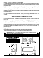
2. GENERAL INSTALLATION INSTRUCTIONS:
Ensure gas supply and gas type, as shown on unit data plate agree. (Data plate is located on the right side
panel of unit).
Unit installation must conform with the National Fuel Gas Code, ANSI Z223.1-1996, the National Gas
Installation Code, CAN/CGA-B149.1, or the Propane Installation Code, CAN/CGA-B149.2 as applicable
and in accordance with local codes.
Screw legs into the permanently fastened nuts on the four corners of the unit and tighten by hand. Level the
unit by turning the adjustment screw at the bottom of each leg. Do not slide unit with legs mounted, lift if
necessary to move unit.
Pipe gas supply to unit.
Pipe threading compound must be resistant to the action of liquefied petroleum gases.
These units are suitable for installation on combustible and noncombustible surfaces.
concealed, a claim must be made with the delivering carrier.
A) Apparent damage or loss must be noted on the freight bill at the time of delivery. It must then be signed by
the carrier representative (Driver). If this is not done, the carrier may refuse the claim. The carrier can supply
the necessary forms.
B) Concealed damage or loss if not apparent until after equipment is uncrated, a request for inspection
must be made to the carrier within 15 days. The carrier should arrange an inspection. Be certain to hold all
contents and packaging material.
Installation and start-up should be performed by a qualified installer who thoroughly read, understands and
follows these instruction.
If you have questions concerning the installation, operation, maintenance or service of this product, write
Technical Service Department APW Wyott Foodservice Equipment Company, P.O. Box 1829, Cheyenne,
WY 82003.
!
!
Warning: DO NOT use an open flame to check for leaks. Check all gas piping for leaks
with a soap and water solution before operating unit.
3. SPECIFICATIONS
CLEARANCES
Sides Rear Floor
0” 6” 4”

4. LIGHTING INSTRUCTIONS
Lighting instructions are located on the rear panel. Access to the pilot valves are gained through openings
in the front panel. Access to the pilot burner is gained by removing the top grate.
1. Turn all burners to the “OFF” position.
2. Turn on the main gas supply to the unit.
3. Light the pilot and adjust the pilot regulating valve to give a stable pilot flame.
4. If the pilot is out, turn all control knobs to the “OFF’ position. Wait 5 minutes before attempting to
light the pilot.
5. To adjust the pilot flame, turn adjusting screw on the pilot valve to increase or decrease the size of
the pilot flame. Adjust until the pilot flame is approximately ½” (1 2mm) to 3/4” (19mm) tall.
Since the burner is lit from a constantly burning pilot, turn the control knob to “HI” to put the unit into
operation; then adjust to any desired position between “LO” and “HI”.
For efficient burner operation, a proper balance of gas volume and primary air supply must be
maintained which will result in complete combustion. Insufficient air supply results in a yellow
streaming flame. Primary air supply is controlled by an air shutter on the burner.
Loosen the screws on the front of the venturi, and adjust the air shutter to eliminate the yellow on
the burner flame. Lock the air shutter in place by tightening the screws.
All burners are lit from constantly burning pilots, turning the control valve as desired is all that is
required to put the unit in service.
Do not permit fans to blow directly on the unit. Wherever possible, avoid open windows next to the
unit’s sides or back. Avoid wall type fans which create air cross-currents within the room.
It is also necessary that sufficient air should be allowed to enter the room to compensate for the
amount of air removed by any ventilating system. Otherwise, a subnormal atmosphere will occur,
adversely affecting operation and causing undesirable working conditions.
A properly designed and installed hood will act as the heart of the ventilating system for the room or
area in which the unit is installed, and will leave the unit independent of changing draft conditions.
All valves must be checked and lubricated periodically. Consult the authorized service
representative in your area.
Lighting Pilot Burner:
Burner Ignition
Main Burner Air Supply:
5. MAINTENANCE
.
1. Thoroughly clean back, sides, top and front of unit.
2. Clean grates daily.
Daily:
!
!

Weekly:
Note:
1. Clean unit thoroughly. Clean stainless steel or chromed surfaces with a damp cloth and polish with
a soft, dry cloth. A detergent may be used for cleaning. To remove discolorations, use a non-
abrasive cleaner.
2. To clean the drip pan: Remove the drip pan by grabbing the handle and pulling it out of the opening
in the front panel. To replace the pan, reverse this procedure.
3. Burner air shutter openings must be kept clean.
4. Main burner ports must be kept clean. To clean burners, boil them in a strong solution of lye water
for 15 to 20 minutes. Then either brush with a wire brush or clean gas ports with a sharp-pointed
metal instrument to insure open ports.
For conversion from natural gas to propane (L.P.).
This conversion should be done before connecting the unit to the gas supply.
1. Remove the knobs and front panel.
2. Remove the main burners.
3. Remove the orifice fittings from the valves.
4. Replace the orifice fittings with the size recommended for propane (L.P.).
5. Replace the main burners.
6. Before installing the regulator, remove the cap. With the brass portion of the cap up, you can read
(NAT) on the plastic insert. Snap the insert out of the cap, flip it over and snap back in place. You can
now read (L.P.). Or change the regulator to a L.P. Regulator.
7. Replace the front panel and knobs.
8. Continue with the installation.
Manifold pressure should be checked after the unit is connected to the gas supply. It should be 10
inches (25.4 cm) water column for (L.P.). If not, you can adjust the regulator by turning the white,
plastic insert in the regulator stem: Clockwise increases pressure and counter-clockwise
decreases pressure.
Manifold pressure should be 6 inches (15.2cm) water column for Natural gas. Leak test all joints.
If you should have any questions or problems, contact your nearest APW Wyott Service
Representative.
6. CONVERSION
!
!

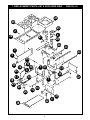
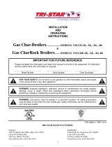
7. REPLACEMENT PARTS LIST & EXPLODED VIEW GHP-2H (CE)
1
2
3
4
5
6
7
8
11
13
14
15
16
17
18
19
20
21
22
23
24
25
25
26
27
28
29
30
31
32
33
34
35
36
37
38
39
12

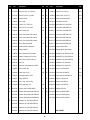
Item P/N Description Quan Item P/N Description Quan
1
2
3
4
5
6
7
8
9*
10*
11
12
13
14
15
16
17
18
19
20
21
22
23
24
25
8417100
8175900
8170700
2065916
8196601
81973-00
2092621
2066852
8824302
8824304
8824306
8824310
8838900
2034000
2065634
2065635
2065641
2066154
2067300
2066842
2068200
2092512
2092517
8632000
8705800
21815522
21815529
21815530
21815531
21815533
21815534
21815535
21815813
Nut, Hex, KEPS 10-32
Screw, 10-32 X 1/2 Tr Hd, SS
Screw, 10-32x1/2, Type AB
Gasket, Burner
Nut, U-type
T/S #10 X ½ TPB Tr Hd
Pipe, 3/4" Sch. 40, 20-5/8
Hood, Orifice, #52
Decal, Front Panel GHP 2 Burner
Decal, Front Panel GHP 4 Burner
Decal, Front Panel GHP 6 Burner
Decal, Dial Plate GHPW
Manual, GHP-H Champion Ii
Nipple, 3/8 NPT
Nut, Compression 3/8-24 Brass
Sleeve, Compression For 3/16ø
Valve, Pilot 1/8" NPT Dual 3/16"
Pilot, Top
Regulator, Convertable 3/4 ½ PSIG
Hood, Orifice, #42
Valve, Gas, On-Off
Coupling,3/4x3/8,F-F,NPT
Plug, 1/8 NPTM
Leg, 4" Adj., 2000 Lb Cap.
Knob, Med. Duty Unit
Support, Drip Pan,GHP/GHPS
Support, Burner/pilot -2HGHP/GHPS
Support, Burner/pilot -4HGHP/GHPS
Support, Burner/pilot -6HGHP/GHPS
Manifold, 3/4" Pipe -2HGHP/GHPS
Manifold, 3/4" Pipe -4HGHP/GHPS
Manifold, 3/4" Pipe -6HGHP/GHPS
Manifold, 3/4" Pipe -3HGHP/GHPS
Varies
4
Varies
Varies
4
4
Varies
Varies
1
1
1
Varies
1
1
Varies
Varies
1
Varies
1
Varies
Varies
1
1
4
Varies
Varies
2
2
2
1
1
1
1
26
27
28
29
30
31
32
33
34
35
36
37
38
39
2065900
2065913
2065914
2201610
21813313
21815584
218203-19
218204-11
218205-19
218155-27
218131-15
218132-15
21815528
21815585
21815538
21815539
21815540
21815581
21815815
21815564
21815565
21815566
218203-23
218204-23
218205-23
218203-20
21815593
21815594
21815595
Burner, Cast, GHP/GHPS
Venturi, Front, 5.85" Lg
Venturi, Rear, 12.578" Lg.
Grate, Individual, GHP-2H
Side Panel, LH & RH
Side Panel, LH & RH GHPW
Front Panel, GHP/GHPS-2H
Front Panel, -4HGHP/GHPS
Front Panel, -6HGHP/GHPS
Back Panel -2HGHP/GHPS
Back Panel -4HGHP/GHPS
Back Panel -6HGHP/GHPS
Support, Burner Side
Support, Burner Side GHPW
Weldment, Top, -2HGHP/GHPS
Weldment, Top, -4HGHP/GHPS
Weldment, Top, -6HGHP/GHPS
Weldment, Top, GHPW-2H
Weldment, Top, GHPW-3H
Tube, Front Pilot GHP-H
Tube, Rear Pilot GHP-H
Tube, Rear Pilot Step GHP-H
Support, Leg GHP-2H
Support, Leg GHP-4H
Support, Leg GHP-6H
Weldm't, Drip Pan
Step, 12" Weldm't GHPS
Step, 24" Weldm't GHPS
Step, 36" Weldm't GHPS
Varies
Varies
Varies
Varies
2
2
1
1
1
1
1
1
2
2
1
1
1
1
1
Varies
Varies
Varies
2
2
2
Varies
1
1
1
*NOT SHOWN

NOTES:

NOTES:


R
APW WYOTT Foodservice Equipment Company
P.O. Box 1829
Cheyenne, WY 82003
+1 (307) 634-5801 Phone +1 (800) 752-0863 Toll Free
+1 (307) 637-8071 Fax www.apwwyott.com
-
 1
1
-
 2
2
-
 3
3
-
 4
4
-
 5
5
-
 6
6
-
 7
7
-
 8
8
-
 9
9
-
 10
10
-
 11
11
-
 12
12


Ask a question and I''ll find the answer in the document
Finding information in a document is now easier with AI
Related papers
-
APW Wyott Gas Hot Plate GHPW-2H Operating instructions
-
-
 APW Wyott RHC-6 User manual
-
APW Wyott RTR-8 Installation And Operating Instructions Manual
-
-
 APW Wyott DTS-91 Operating instructions
-
 APW Wyott JR-2000 Operating instructions
-
 APW Wyott GF-15H Operating instructions
-
 APW Wyott SEHP User manual
-
APW Wyott RTR-4 Operating instructions


Other documents
-
Patriot PT-HP12-M User manual
-
Dyna-Glo DGSS962CBO-DC Operating instructions
-
CPG CK-HPSU212 Boasting 6 Powerful 30000 BTU Burners User manual
-
CPG CK-HPSU212 Gas Step Up Hot Plate User manual
-
CFM APW-42 User manual
-
Pleasant Hearth VFL2-SO18DT User manual
-
COOKING PERFORMANCE GROUP 351RCPG36NL User manual
-
 Tri-Star TSGCB-48i Installation And Operating Instructions Manual
-
 Holman Cooking/Star Mfg GHP2 Operating instructions
-
Lang GHP6 Operating instructions

