Page is loading ...

Quick Start Guide
Network Bullet Camera
MVCLOUD-201

Network Ernitec Cloud Bullet Camera·Quick Start Guide
1
About this Manual
This Manual is applicable to JCAM-201 Network Ernitec Cloud
Camera.
The Manual includes instructions for using and managing the
product. Pictures, charts, images and all other information here in
after are for description and explanation only. The information
contained in the Manual is subject to change, without notice, due to
firmware updates or other reasons. Please find the latest version in
the company website
Please use this user manual under the guidance of professionals.
Legal Disclaimer
REGARDING TO THE PRODUCT WITH INTERNET ACCESS, THE USE OF
PRODUCT SHALL BE WHOLLY AT YOUR OWN RISKS. OUR COMPANY
SHALL NOT TAKE ANY RESPONSIBILITES FOR ABNORMAL OPERATION,
PRIVACY LEAKAGE OR OTHER DAMAGES RESULTING FROM CYBER
ATTACK, HACKER ATTACK, VIRUS INSPECTION, OR OTHER INTERNET
SECURITY RISKS; HOWEVER, OUR COMPANY WILL PROVIDE TIMELY
TECHNICAL SUPPORT IF REQUIRED.
SURVEILLANCE LAWS VARY BY JURISDICTION. PLEASE CHECK ALL
RELEVANT LAWS IN YOUR JURISDICTION BEFORE USING THIS
PRODUCT IN ORDER TO ENSURE THAT YOUR USE CONFORMS THE
APPLICABLE LAW. OUR COMPANY SHALL NOT BE LIABLE IN THE
EVENT THAT THIS PRODUCT IS USED WITH ILLEGITIMATE PURPOSES.
IN THE EVENT OF ANY CONFLICTS BETWEEN THIS MANUAL ANDTHE
APPLICABLE LAW, THE LATER PREVAILS.

Network Ernitec Cloud Bullet Camera·Quick Start Guide
2
Regulatory Information
FCC Information
FCC compliance: This equipment has been tested and found to
comply with the limits for a Class A digital device, pursuant to part 15
of the FCC Rules. These limits are designed to provide reasonable
protection against harmful interference when the equipment is
operated in a commercial environment. This equipment generates,
uses, and can radiate radio frequency energy and, if not installed and
used in accordance with the instruction manual, may cause harmful
interference to radio communications. Operation of this equipment in
a residential area is likely to cause harmful interference in which case
the user will be required to correct the interference at his own
expense.
FCC Conditions
This device complies with part 15 of the FCC Rules. Operation is
subject to the following two conditions:
1. This device may not cause harmful interference.
2. This device must accept any interference received, including
interference that may cause undesired operation.
EU Conformity Statement
This product and - if applicable - the supplied
accessories too are marked with "CE" and comply
therefore with the applicable harmonized European
standards listed under the EMC Directive 2004/108/EC, the RoHS
Directive 2011/65/EU.

Network Ernitec Cloud Bullet Camera·Quick Start Guide
3
2012/19/EU (WEEE directive): Products marked with
this symbol cannot be disposed of as unsorted
municipal waste in the European Union. For proper
recycling, return this product to your local supplier
upon the purchase of equivalent new equipment, or dispose of it at
designated collection points. For more information see:
www.recyclethis.info
2006/66/EC (battery directive): This product contains
a battery that cannot be disposed of as unsorted
municipal waste in the European Union. See the
product documentation for specific battery
information. The battery is marked with this symbol, which may
include lettering to indicate cadmium (Cd), lead (Pb), or mercury (Hg).
For proper recycling, return the battery to your supplier or to a
designated collection point. For more information see:
www.recyclethis.info
Industry Canada ICES-003 Compliance
This device meets the CAN ICES-3 (A)/NMB-3(A) standards
requirements.
Safety Instruction
These instructions are intended to ensure that user can use the
product correctly to avoid danger or property loss.
The precaution measure is divided into “Warnings” and “Cautions”
Warnings: Serious injury or death may occur if any of the warnings
are neglected.
Cautions: Injury or equipment damage may occur if any of the
cautions are neglected.

Network Ernitec Cloud Bullet Camera·Quick Start Guide
4
Warnings
● In the use of the product, you must be in strict compliance with
the electrical safety regulations of the nation and region. Please
refer to technical specifications for detailed information.
● Input voltage should meet both the SELV (Safety Extra Low
Voltage) and the Limited Power Source with 12 VDC according to
the IEC60950-1 standard. Please refer to technical specifications
for detailed information.
● Do not connect several devices to one power adapter as adapter
overload may cause over-heating or a fire hazard.
● Please make sure that the plug is firmly connected to the power
socket. When the product is mounted on wall or ceiling, the
device shall be firmly fixed.
● If smoke, odor or noise rise from the device, turn off the power
at once and unplug the power cable, and then please contact
the service center.
Warnings Follow these
safeguards to prevent
serious injury or death.
Cautions Follow these
precautions to prevent
potential injury or material
damage.

Network Ernitec Cloud Bullet Camera·Quick Start Guide
5
● Proper configuration of all passwords and other security settings
is the responsibility of the installer and/or end-user.
Cautions
● Make sure the power supply voltage is correct before using the
camera.
● Do not drop the camera or subject it to physical shock.
● Do not touch sensor modules with fingers. If cleaning is
necessary, use clean cloth with a bit of ethanol and wipe it
gently. If the camera will not be used for an extended period,
please replace the lens cap to protect the sensor from dirt.
● Do not aim the camera at the sun or extra bright places.
Blooming or smearing may occur otherwise (which is not a
malfunction), and affect the endurance of sensor at the same
time.
● The sensor may be burned out by a laser beam, so when any
laser equipment is in using, make sure that the surface of sensor
will not be exposed to the laser beam.
● Do not place the camera in extremely hot, cold (the operating
temperature shall be-30°C ~+60°C, or -40°C ~ +60°C if the
camera model has an “H” in its suffix), dusty or damp locations,
and do not expose it to high electromagnetic radiation.
● To avoid heat accumulation, good ventilation is required for
operating environment.
● Keep the camera away from liquid while in use.

Network Ernitec Cloud Bullet Camera·Quick Start Guide
6
● While in delivery, the camera shall be packed in its original
packing, or packing of the same texture.
● Regular part replacement: a few parts (e.g. electrolytic
capacitor) of the equipment shall be replaced regularly
according to their average enduring time. The average time
varies because of differences between operating environment
and using history, so regular checking is recommended for all the
users. Please contact with your dealer for more details.
● Improper use or replacement of the battery may result in hazard
of explosion. Replace with the same or equivalent type only.
Dispose of used batteries according to the instructions provided
by the battery manufacturer.
● If the product does not work properly, please contact your
dealer or the nearest service center. Never attempt to
disassemble the camera yourself. (We shall not assume any
responsibility for problems caused by unauthorized repair or
maintenance.)

Network Ernitec Cloud Bullet Camera·Quick Start Guide
7
Table of Contents
1 Appearance Description ................................................................. 8
1.1 Overview of Type I Bullet Camera ................................... 8
1.2 Overview of Type II Bullet Camera ................................ 10
1.2.1 Resetting the Camera ......................................... 11
1.2.2 Setting the WPS Protocol.................................... 12
1.2.3 PoE Power Supply Configuration (Optional)........ 13
2 Installation .................................................................................... 14
2.1 Installation of the Bullet Camera ................................... 15
2.2 Installation of Network Cable Water-proof
Jacket(Optional) ....................................................................... 18
3 Setting the Network Camera over the LAN .................................. 21
3.1 Wiring ........................................................................... 21
4 Register Camera Into Ernitec Cloud Services ................................ 22
4.1 Register Camera from dashboard for professionals ....... 22
4.1.1 Register Camera ................................................. 22
4.1.2 Unregister Camera ............................................. 24
4.2 Register Camera from the web site Ernitec-Cloud ......... 25
5 Download “Ernitec Cloud” App on IOS/Android .......................... 26
6 Wifi Network Setup ...................................................................... 29
6.1 With WPS button .......................................................... 29
6.2 With “Ernitec Cloud” Mobile App Or Ernitec-Cloud
website…………………………………………………………….………………29

Network Ernitec Cloud Bullet Camera·Quick Start Guide
8
1 Appearance Description
1.1 Overview of Type I Bullet Camera
1
2
3
4
5
6
9
7
8
Figure 1-1 Type I Bullet Camera

Network Ernitec Cloud Bullet Camera·Quick Start Guide
9
Table 1-1 Description
No.
Description
No.
Description
1
Mounting Base
4
Lens
2
Back Box
5
Sun Shield
3
Front Box
6
Power Cable
7
Reset Button
8
GND Screw
9
10/100M Self-adaptive
Ethernet Interface
Type I camera does not support the function of Wi-Fi or SD card.
Press Reset button about 10s when the camera is power on or
rebooting to restore the default settings, including the user name,
password, IP address, port No., etc.

Network Ernitec Cloud Bullet Camera·Quick Start Guide
10
1.2 Overview of Type II Bullet Camera
1
2
4
3
5
6
7
9
8
10
11
Figure 1-2 Type II Bullet Camera
Table 1-2 Description

Network Ernitec Cloud Bullet Camera·Quick Start Guide
11
No.
Description
No.
Description
1
Mounting Base
7
microSD Card Slot
2
Main Body
8
Power Supply Interface
No.
Description
No.
Description
3
Sun Shield
9
10/100M Self-adaptive
Ethernet Interface
4
Lens
10
PoE Cable
5
Adjusting Nut
11
GND Screw
6
WPS/RESET Button
1.2.1 Resetting the Camera
Move the RESET/WPS Cover, and press WPS/RESET button about 10s
when the camera is power on or rebooting to restore the default
settings, including the user name, password, IP address, port No., etc.

Network Ernitec Cloud Bullet Camera·Quick Start Guide
12
WPS/RESET
Figure 1-3 WPS/RESET Button
WPS function and Reset function share the same button. The
button works as a reset button only when you press it when the
camera is powered on.
1.2.2 Setting the WPS Protocol
A wireless router with the WPS function is required to enable the
WPS function of the camera. Refer the steps below.
Steps:
1. Enable the WPS function of your router. Refer to the operation
guide of your router for detailed procedures.
2. Press the WPS/RESET button (about 2s) on the camera to join in
the wireless network.

Network Ernitec Cloud Bullet Camera·Quick Start Guide
13
WPS/RESET
Figure 1-4 WPS/RESET Button
You can also press the WPS button on the camera first and then
enable the WPS function on the router to establish the
connection. But the WPS function of the router must be turned
on within 120s right after pressing the WPS/RESET button on the
camera.
Screw the microSD/RESET/WPS Cover back to the camera after all the
settings.
1.2.3 PoE Power Supply Configuration (Optional)
This type of bullet camera supports PoE power supply. You can power
the camera by connecting both DC 12V interface and the Ethernet
interface. Or you can connect the Ethernet interface only.

Network Ernitec Cloud Bullet Camera·Quick Start Guide
14
2 Installation
Before you start:
● Make sure the device in the package is in good condition and all
the assembly parts are included.
● The standard power supply is 12V DC, please make sure your
power supply matches with your camera.
● Make sure all the related equipment is power-off during the
installation.
● Check the specification of the products for the installation
environment.
● Make sure that the wall is strong enough to withstand four times
the weight of the camera and the bracket.
For the camera that supports IR, you are required to pay attention to
the following precautions to prevent IR reflection:
● Dust or grease on the dome cover will cause IR reflection. Please
do not remove the dome cover film until the installation is
finished. If there is dust or grease on the dome cover, clean the
dome cover with clean soft cloth and isopropyl alcohol.
● Make sure that there is no reflective surface too close to the
camera lens. The IR light from the camera may reflect back into
the lens causing reflection.
● The foam ring around the lens must be seated flush against the
inner surface of the bubble to isolate the lens from the IR LEDS.
Fasten the dome cover to camera body so that the foam ring and
the dome cover are attached seamlessly.

Network Ernitec Cloud Bullet Camera·Quick Start Guide
15
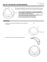
2.1 Installation of the Bullet Camera
Both wall mounting and ceiling mounting are suitable for the bullet
camera. Wall mounting will be taken as an example in this section.
You can take steps of wall mounting as a reference if ceiling mounting
is adopted.
Steps:
1. Drill the screw holes in the wall according to the drill template.
Ceiling Mounting
Hole
Hole
Hole
Figure 2-1 Drill Template
2. Route the corresponding cables.
3. Secure the camera to the wall with the supplied Screws.

Network Ernitec Cloud Bullet Camera·Quick Start Guide
16
Figure 2-2 Secure the Camera to the Ceiling
4. Connect the corresponding power/Video Output cables.
5. Adjust the surveillance angle.
0°~90°
Adjusting Nut
0°~360°
0°~360°
Figure 2-3 3-axis Adjustment
1). Loosen the adjusting nut.
2). Adjust the pan direction [0° to 360°].
3). Adjust the tilt direction [0° to 90°].

Network Ernitec Cloud Bullet Camera·Quick Start Guide
17
4). Rotate the camera [0° to 360°] to adjust the lens to the
surveillance angle.
5). Tighten the adjusting nut to complete the installation.

Network Ernitec Cloud Bullet Camera·Quick Start Guide
18
2.2 Installation of Network Cable Water-proof
Jacket(Optional)
Purpose:
If the camera is installed outdoor, you can adapt the water-proof
accessory for the network cable after the camera is secured on the
installation surface.
①
②
③
④
⑤
⑥ ⑦
Figure 2-4 Water-proof Accessory Components
Table 2-1 Components
No.
Components
1
Camera’s Network Interface Socket
2
O-Type Gasket
3
Network Plug
4
Waterproof End cap
5
Waterproof Rubber Gasket
6
Lock Nut
7
Network Cable from Router/Switch

Network Ernitec Cloud Bullet Camera·Quick Start Guide
19
Camera
Switch/Router
Align the snap and notch.
i. Insert ⑤ into ④.
ii. Secure ⑥ with ④.
Figure 2-5 Water-proof Accessory Installation
Steps:
1. Feed the plug less network cable ⑦ through the lock nut ⑥,
waterproof rubber gasket ⑤ (rubber gasket inset ridge must
face waterproof end cap), and the water-proof end cap ④ in
order.
2. Crimp an RJ-45 network plug onto the end of the cable, taking
care to insert the twisted pairs of wires in correct order.
3. Place the O-type gasket ② onto the end of the camera’s
network interface socket ①.
/