Blodgett SG3240E Operating instructions
- Category
- Ovens
- Type
- Operating instructions
This manual is also suitable for

BLODGETT OVEN COMPANY
www.blodgettcorp.com
50 Lakeside Avenue, Box 586, Burlington, Vermont 05402 USA Telephone (800) 331-5842, (802) 860-3700 Fax: (802)864-0183
PN M9739 Rev C (6/01)
E 2000 --- G.S. Blodgett Corporation
SG3240E AND SG3240G
CONVEYOR OVENS
INSTALLATION -- OPERATION -- MAINTENANCE
SG3240E ET SG3240G
FOURS À BAND E TR ANSPOR TEUSE
MANUEL D’INSTALLATION -- FONCTIONNEMENT -- ENTRETIEN

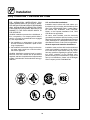
IMPORTANT
FORYOURSAFETY
Do not store or use gasoline or other flammable vapors or liquids in the v icinity
of this or any other appliance.
AVERTIS SEMENT
Ne pas entrepos er ni utiliser de l’ess ence ni d’autres vapeurs ou liquides inflam-
mables dans le vois ina ge de cet appar iel, ni de tout autre appareil.
INSTRUCTIONS TO BE FOLLOWED IN THE EVENT THE USER SMELLS GAS
MUST BE POSTED IN A PROMINENT LOCATION. THIS INFORMATION MAY BE
OBTAINED B Y CONTACTING YO UR LO CAL GAS SUPPLIER.
LES INSTRUCTIONS À RESPECTER AU CAS OÙ L’UTILISATEUR PERÇOIT UNE
ODEUR DE GAZ DOIVENT ÊTRE AFFICHÉES DANS UN ENDROIT BIEN VISIBLE.
VOUS POUVEZ VOUS LES PROCURER AUPRÈS DE VOTRE FOURNISSEUR DE
GAZ LOCAL.
WA RN I N G: IMP ROPER INS TA LL ATION , AD JUS TMEN T, ALTERATIO N , SERVIC E OR
MAI N TENA N C E CAN CAUSE PRO P ERTY DA MA GE, INJURY OR DEATH. READ TH E
INST ALLA TION, OPERA TING AND MAINTENANCE INSTRUCTIONS THOROUGHLY
BEFORE INSTALLING OR SERVICING THIS EQUIPMENT
A V ERTISSEMENT: UNE INSTALL ATION, UN AJUS TEMEN T, UNE ALTÉRATI O N , UN
SERV I CE OU UN ENTRETIEN NON CON FO RME A UX NO RMES PEUT CA US ER DES
DO MMA GES À LA PRO PRIÉTE, DES BLESS URES OU LA MORT. LISEZ ATTENTI V E-
MENT LES DIRECTIVES D’I N S TALLATION, D’OP ÉRATIO N ET D’EN TRETI EN AV A N T
DE F A IRE L’IN S TALLATION OU L’EN TRETI EN DE CET ÉQUIP EMEN T.
The information contained in this manual i s important for the proper installation,
use, and maintenance of this oven. Adherence to these procedures and instruc-
tions will result in satisfactory baking results and long, trouble free service.
Please read this manual carefully and retain it for future reference.
Les informatio ns données dans le présent manuel so nt importantes pour installer,
utiliser et entretenir cor r ect em en t ce fo u r. Le res pect de ces instr u ct ions et pro cé-
dures permettr a d’obt enir de bons résultats de cuiss o n et une longue durée de ser-
vice sans problèmes. Veuillez lire le présent manuel et le conserver pour pouvoir
vou s y reporter à l’avenir.
Errors: Descriptive, typographic or pictorial errors are subject to correction. Specifica-
tions are subject to change without notice.
Erreurs:Les erreurs de description, de typographie ou d’illustration font l’objet de
corrections. Les caractéristiques sont sujettes à modifications sans préavis.
Page is loading ...

Your Service Agency’s Address:
Adressedevotreagencedeservice:
Model/Modèl:
Serial Number/Numéro de série:
Your oven was installed by/
Installateur de votre four:
Your oven’s installation was checked by/
Contrôleur de l’installation de votre four:

Table of Contents/Table des Matières
Introduction
Oven Description and Components 2.....
Oven Specifications 4...................
Installation
Delivery and Inspection 5...............
Oven Location and Ventilation 6..........
Oven Assembly 8......................
Oven Supports 8......................
Stacking the Ovens (if applicable) 10.....
Conveyor Support A ngles 11............
Conveyor Belt Direction 12..............
Standard Conveyor Assembly 13........
Optional Folding Conveyor 16...........
Conveyor Belt Tensioner 17.............
Crumb Pans 17........................
Optional Remote Computer Control 18...
Optional Vent Cover/Chimney 19.........
Utility Connections ---
Standards and Codes 20.................
Gas Connection 21......................
Electrical Connection 24.................
Operation
Safety In formation 25....................
Standard Manual Control 26..............
Programmable Menu Control 28..........
Oven Adjustments for Cooking 30.........
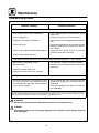
Maintenance
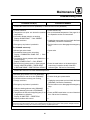
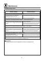
Cleaning 32............................
Troubleshooting Guide 34................
Introduction
Description et Composantes du Four 38...
Caractéristiques du Four 40..............
Installation
Livraison et Inspection 42................
Emplacement et Ventilation du Four 43.....
Montage du Four 45.....................
Supports du Four 45...................
Empilage des Fours (le cas échéant) 47..
Cornières du Convoyeur 48.............
Sens de la courroie du convoyeur 49.....
Montage du Convoyeur Standard 50.....
Convoyeur Pliant en Option 53..........
Tensionneur de la Courroie
de Convoyeur 54......................
Ramasse-Miettes 54....................
Contrôle à D istance par Ordinateur
(en option) 55.........................
Cheminée/Couvert d’Évent (en option) 56.
Branchement des Sources d’ A limentation ---
Normes et Codes 57.....................
Branchement du Gaz 58.................
Branchement à l’Alimentation
Électrique 62...........................
Fonctionnement
Informations sur la Sécurité 63............
Le Contrôle Manuel Standard 64..........
Contrôle Programmable du M enu 66......
Ajustements du Four Pour la Cuisson 69...
Entretien
Nettoyage 71...........................
GuidedeDépannage 73.................

Introduction
2
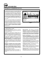
Oven Description and Components
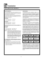
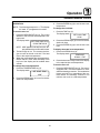
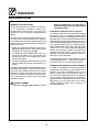
Cooking in a conveyor oven differs from cooking
in a conventional deck or range oven since heated
air is constantly recirculated over the product by
a fan in an enclosed chamber. The jets of moving
air continually strip away the layer of cool air sur-
rounding the product, quickly allowing the heat to
penetrate. The result is a high quality product,
cooked at a lower temperature in a shorter amount
of time.
This Blodgett conveyo r oven represents the latest
advancement in energy efficiency, reliabi li ty, and
ease of operation. Heat normally lost, is recirculated
within the cooking chamber resulting in substantial
reductions in energy consumption, a coo l er kitchen
enviro nment and enhanced oven performance.
AirFlowPatternforBlodgettConveyorOvens
Heated Air
Combustion
Chamber
Return Air
Air Plate
Blower
Nozzles
Conveyor
Figure 1
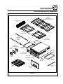
OVEN COMPONENTS
Conveyor Belt --- stainless steel chain link (con-
veyor) belt that carries product through the oven.
Conveyor Belt Master Links --- a llow e a sy r e mo v -
al of the conveyor belt for more thorough mainte-
nance a nd cleaning. Identified by locating double
spaces between regular links on the belt.
Conveyor Rack Assembly (drive & idle sides) ---
located on both ends of the oven deck. The drive
side has a drive shaft and sprocket which slide into
the electrical box. The conveyor can be removed
as one piece without removing the belt.
Optional Folding Conveyor Rack Assembly ---
conveyor belt and rack a ssembly that carries
product through the oven. This rack folds for ease
of removal in small spaces. The conveyor can be
removed a s one piece without removing the belt.
Conveyor Belt Tensioners --- maintain tension on
theconveyorbelt.
Electrical Box --- contains electrical components,
wiring, cooling fans, drive motor, drive chain, and
combustion blower/burner a ssembly (gas ovens
only) or electric elements (electric ovens only).
Drive Motor --- provides power t o move the con-
veyor belt. The operator and control system deter-
mine the speed. Belt travel direction (left to right or
right to left) is factory set and is easily changed.
Drive Chain --- connects the drive motor sprocket
to the conveyor drive shaft sprocket.
Baking Chamber --- products pass through the
baking chamber on the belt.
Nozzles --- distribute heated air from the bottom
of the baking chamber. Located inside the oven,
undertheconveyorbelt.
Nozzle Support Bracket --- removable bar that lo-
cates the front end of the nozzles. Located just in-
side the oven’s front door beneath the nozzles.
Air Flow Plate --- distributes heated air from the
top of the baking chamber.
Conveyor Support Angle Bars --- p ro vi d e s u p -
portforconveyorrackassembly.
Crumb Pans --- catch crumbs from products on
the conveyor. Located under conveyor belt at both
ends of the baking chamber.
Operator Controls --- used to control oven tem-
perature, belt speed and other functions.
Ignition Control Reset Button (gas ovens only) ---
resets igniti o n control/gas burner after a lockout. Lo-
cated o n the l o wer panel of the contro l box.
Emergency Stop Button --- FO R EMERGENCY
USE ONLY (damage may occur)! Press the red palm
switch located next to the operator control to shut
down the oven and stop the convey or.
Front Access Door --- opens for access to cook-
ing chamber allowing for easier cleaning.

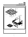
Introduction
3
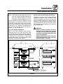
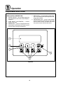
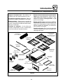
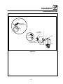
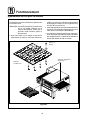
Oven Description and Components
Air Flow
Plate
Front Access
Door
Belt
Tensioner
Belt
Tensioner
Idle Side
Crumb Pan
Drive Side
Crumb Pan
Conveyor
Support
Angles
Wire Conveyor
Belt
Drive Side
Conveyor Rack
Idle Side
Conveyor Rack
Optional
Folding Conveyor
(shown without belt for clarity)
Integral
Operator Control
Nozzles
Nozzle Support
Bracket
Operator
Control
Remote
Mounting Bracket
Product
Stop
Remote
Housing
Figure 2

Introduction
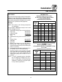
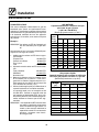
4
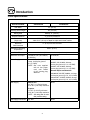
Oven Specifications
SPECIFICATIONS SG3240G/AA SG3240E/AA
Belt Width 32” (81 cm)
Cooking Zone Length 40” (102 cm)
Baking Area 8.89 Sq. Ft. (0.83 m
2
)
Product Clearance 4” (10.2 cm) maximum
Dimensions
(single unit)
77” x 53”* x 24” (196 cm x 135 cm* x 61 cm)
*Add 13.65” (35 cm) to depth for triple stack caster cradles
Minimum
Wall Clearance
0” (0 cm) from rear and side
Maximum Operating
Temperature
600_F (315_C)
Bake Time 1 minute (minimum) 30 minutes (maximum)
Maximum Heat Input 110,000 BT U/Hr. (32.2 kW/Hr.)
(116 MJ/hr)
27.0 kW/Hr.
Power Supply 208-240VAC, 1Φ, 50/60 Hz,
5 amp, 2 wire plus ground
(L1, L2, GND)
NOTE: Gas oven supplied
with six foot power
cord with NEMA
L6 -15P locking plug
attached.
U.S. and Canadian (or similar)
208VAC, 3Φ, 50/60Hz, 80 amp,
3 wire plus ground (L1, L2, L3, GND)
240VAC, 3Φ, 50/60Hz, 69 amp,
3 wire plus ground (L1, L2, L3, GND)
General Export and Australia
230/400VAC, 3Φ WYE, 50/60Hz, 41.5 amp,
4 wire plus ground (L1, L2, L3, N, GND)
240/415VAC, 3Φ WYE, 50/60Hz, 40 amp,
4 wire plus ground (L1, L2, L3, N, GND)
Gas Supply Natural Gas:
4.5” W.C. (1. 1 kPa) minimum
10.5” W.C. (2.61 kPa) ma ximum
Propa ne:
11” W.C. (2.74 kPa) minimum
13.0” W.C. (3.23 kPa) ma ximum
NOTE: See rating plate for man-
ifold pre ssure set ting.
None
Gas Supply Connection 3/4” NPT None

Installation
5
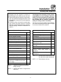
Delivery and Inspection
All Blodgett ovens are shipped in containers to
prevent damage. Upon delivery of your new oven:
D
Inspect the shipping container for external dam-
age. Any evidence of damage should be noted
on the delivery receipt which must be signed by
the driver.
D
Uncrate the oven and check for internal dam-
age. Carriers will accept claims for concealed
damage if notified within fifteen days of delivery
and the shipping container is retained for in-
spection.
The Blodgett Oven Company cannot assume
responsibility for loss or damage suffered in
transit. The carrier assumed full responsibility
for delivery in goo d order when the shipment
was accepted. We are, however, prepared to
assist you if filing a cl aim is necessary.
The oven can now be moved to the installation
site. Check the following list with Figure 2 on page
3 to be sure all items w ere received.
Standard Components
Part Description Qty.
Main oven body 1
Nozzle (shipped installed) 8
Air plate (shipped installed) 1
Conveyor support angle 2
Drivesideconveyorrack 1*
Idle side conveyor rack 1*
Rolledwireconveyorbelt 1*
Extra piece of wire conveyor belt 1
Packet containing: conveyor belt
innerandoutermasterlinks
1*
Belt tensioners 2*
Crumb pans 2
Product stop 1
Oven Supports (legs, casters) 4
Air Plate Hook 1**
Packet containing: 12 3/8-16 hex
head bolts, lockwashers and wash -
ers for legs
1
Owner’s manual 1
NOTE: * shippe d assembled for the option al
foldin g conv e y or
NOTE: ** shipped with bottom or single section
ovens only.
Options
Part Description Qty.
Optional folding conveyor assembly 1
Stacking Kit 1***
Packet containing: 4 alignment pins 1***
Triple stack casters 1****
Optional remote operator control with
attached 50’ cable
1
Optional remote operator control for
10’ cable
1
Optional remote 10’ cable 1
Packet containing: optional remote
operator control cable clamps and
hardware
1
Optional vent cover assembly or
chimney kit
1
NOTE: *** One required for double stacked units
Two required for triple stacked units
NOTE: **** Triple stacked units only

Installation
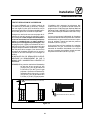
6
Oven Location and Ventilation
OVEN LOCATION
The well planned and proper placement of your
oven will result in long term operator convenience
and satisfactory performance.
The following clearances must be maintained be-
tween the oven and any combustible or non-com-
bustible construction.
SG3240G
D
Oven body sides --- 0” (0 cm)
D
Oven body back --- 0” (0 cm)
SG3240E
D
Oven body sides --- 0” (0 cm)
D
Oven body back --- 0” (0 cm)
The following clearances must be available for
servicing.
All units
D
Oven body sides --- 38” (96.5 cm)
D
Oven body back --- 28” (71 cm)
NOTE: On gas models, routine servicing can usu -
ally be accomplished within the limited
movement provided by the gas hose re-
straint. If the oven needs to be moved fur-
ther from the wall, the gas must first be
turned off and disconnected from the oven
before removing the restraint. Reconnect
the restraint after the oven has been re-
turned to its regular position.
It is essential that a sufficient air supply to the oven
be maintained to provide adequate combustion
and ventilation air.
D
Place the oven in an area that is free of drafts.
D
Keep the oven area free and clear of all combus-
tibles such as paper, cardboard, and flammable
liquids and solvents.
VENTILATION
A mechanically driven ventilation system is re-
quired for the removal of excess heat and cooking
vapors. For gas models, a ventilation system is
also required for t he removal of t he products of
gas combustion. The necessity for a properly de-
signed and installed ventilation system cannot be
over emphasized.
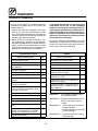
The follow ing are general recommendations and
guidelines for good ventilation. Your specific ap-
plication may require the services of a ventilation
engineer or consultant
The ventilation hood must work well with the build-
ing heating, ventilation and air conditioning
(HVAC) system. The hood exhaust and the supply
air flows should be sized a ppropriately. Supply air
must be provided by either the hood system or the
building HVAC system in order to prevent an ex-
cessive negative pressure in the oven area. Sup-
ply air should replace approximately 80% of the air
flow exhausted by t he hood. The table below can
be used as a guideline, but the correct air flow val-
ues depend on the efficiency of the hood design,
the amount of air flow around the oven, and the
current air flow in and out of the kitchen or oven
area (for existing facilities).
SINGLE
DOUBLE TRIPLE
Exhaust Volume -- CFM (M
3
/min)
800-1000
(23-28)
1200-1800
(34-52)
1800-2500
(52-71)
Supply Requirements -- CFM (M
3
/min)
640-800
(18-23)
960-1440
(27-41)
1440-2000
(41-56)
Ideally supply air would be provided through the
building HVAC system or, secondly, through the
hoodwith an in-line tempering unit. Air supplied di-
rectly from outside the building to the k itchen or
oven area, non-tempered, could be used as sup-
plyairbut the design would have t o accommodate
potential operational and environmental draw-
backs.

Installation
7
Oven Location and Ventilation
NOTE: In NO case should supply air blow at or
near the cooking chamber openings as
that would adversely affect the cooking
consistency and the reliability of the oven.
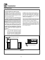
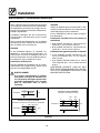
The hood should be sized to completely cover the
equipment plus an overhang of at least 6” (15cm)
on all sides not adjacent to a wall. It may be allow-
able in some jurisdictions to cover just the baking
chamber plus a 6” overhang. The distance from
the floor to the lower edge of the hood should not
exceed 7’ (2.1m). See Figure 3.
U.S. and Canadian installations
Refer to your local ventilation codes. Require-
ments may vary by city, county, province or state.
In the absence of local codes, refer to the National
ventilation code titled, “Standard for the Installation
of Equipment for the Removal of Smoke and
Grease Laden Vapors from Commercial Cooking
Equipment”, NFPA-96-Latest Edition.
General export and Australian installations
Installation must conform with Local and National
installation standards. Local installation codes
and/or requirements may vary. If you have any
questions regarding the proper installation and/or
operation of your B lodgett oven, please contact
your local distributor. If you do not have a local dis-
tributor, please call the Blodgett Oven Company at
0011-802-860-3700.
WARNING:
Failure to properly vent the oven can be
hazardous to the health of the operator
and may result in operational problems,
unsatisfactory baking and possible dam-
age to the equipment.
Damage sustained as a directresult of im-
proper ventilation will not be covered by
the Manufacturer’s warranty.
6” (15.2 cm)
Minimum
24”
(61 cm)
72” (182 cm)
14.2”
(36.1 cm)
77” (196 cm)
6” (15 .2cm)
Minimum
3” (7.6 cm)
Minimum
Tr ip l e S t a c k --- 2” ( 5. 1 c m )
Double Stack --- 17.25” (43.8 cm)
Single Stack --- 23.25” (59 cm)
0” (0cm) if wall or
6” (15.2 cm)
Figure 3

Installation
8
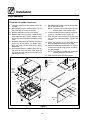
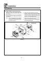
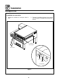
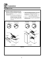
Oven Assembly
OVEN SUPPORTS
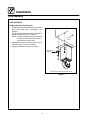
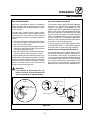
Single and Double Stacked Units
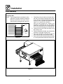
1. Bolt the leg/caster assemblies to the oven with
3/8-16 hex head bolts, lockwashers a n d
washers.
On gas models attach the restraint bracket to
the left rear leg as shown in Figure 4.
NOTE: Install the locking casters on the front
of the oven. The front of the oven con-
tains the front access door.
2. Have several persons carefully lift the oven off
thepalletandsetitontothecasters.
3. Engage the brakes on the front casters.
Left rear leg and strain relief bracket shown
Strain Relief
Bracket
Front of
Oven
Figure 4

Installation
9
Oven Assembly
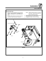
Triple Stacked Units
1. Mount the caster assemblies to the oven with
3/8-16 x .125 cap s crews, lockwashers and
washers. See Figure 5 for correct caster orien-
tation.
On gas models attach the restraint bracket to
theleftrearcasterasshowninFigure5.
NOTE: Install the locking casters on the front
of the oven. The front of the oven con-
tains the front access door.
2. Have several persons carefully lift the oven off
thepalletandsetitontothecasters.
3. Engage the brakes on the front casters.
Strain Relief
Bracket
See View A
View A
Figure 5

Installation
10
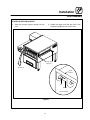
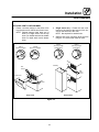
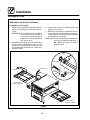
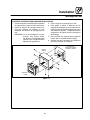
Oven Assembly
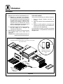
STACKING THE OVENS (if applicable)
1. Install the supports on the bottom unit as de-
scribed.
2. Have several persons carefully lift the oven off
thepalletandsetitontothecasters.
3. Engage the brakes on the front casters.
4. Rest the top oven on its back. Install the four
oven alignment pins into the outside corner
mounting holes provided on the bottom of the
oven.
5. Assemble the t hree long stacking trim pieces
on the top of the bottom (or middle) oven.
Align the holes over the holes for the align-
ment pins.
6. Have several persons carefully place the up-
per oven on top of the lower oven. Align the
alignment pins with the knock-out holes in the
top the lower oven.
7. Place the stacking plate on top of the electrical
box on the bottom unit.
NOTE: The back of the plate should line up
with the back of the electrical box.
8. Loosen the three screws on the top of the elec-
trical box side panel on the lower oven.
9. Slide the slots in the bottom of the stacking
trim over the loosened screws . Tighten the
screws.
10. Attach the stacking trim to the side of the
stacking plate with the screw s provided.
11. Attach the heat shield brackets to the bottom
of the control tunnel using screw s , lockwash-
ers and w ashers.
NOTE: The stops on the brackets should be
located away from the control.
12. Slide the heat shield into the brackets.
Stacking
Trim
Oven
Alignment
Pin
Stacking
Plate
Stacking
Plate
Stacking
Trim
Electrical
Box
Alignment
Pin
Oven
Heat
Shield
and
Brackets
Heat
Shield
Heat Shield
Brackets
Stacking
Trim
Figure 6

Installation
11
Oven Assembly
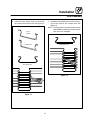
CONVEYOR SUPPORT ANGLES
1. Slide the conveyor support angles into the
oven.
2. Rotate the angle such that the slots in the
brackets engage the pins on the oven.
See View A
View A (Installed)
Conveyor Angle
Supports
Pin
Angle
Support
Bracket
Figure 7

Installation
12
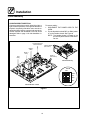
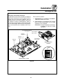
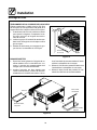
Oven Assembly
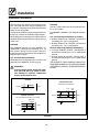
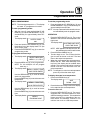
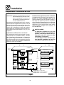
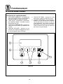
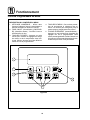
CONVEYOR BELT DIRECTION
Convey or travel is factory set for either left to right or
right to left belt operation. If the oppo site directio n is
required, the pol arity of the drive motor must be re-
versed as follows and the conveyor belt must be re-
moved, reversed and reinstalled or the belt will be
damaged. Refer to page 14 for belt installati on in-
structions.
To reverse pol arity:
1. DISCONNECT THE POWER CORD TO THE
OVEN.
2. Flip the dipswitch marked DIR1 on SW4 (switch
4) o n the interface board. See Fi gure 8.
NOTE: The inte rfa c e board is locate d on the
pull out tray at the bottom of the electri-
cal box.
Heat
Relay
Blower 1
Relay
Circulation Blowers’
Pressure Switch
Switch 4
(See View B)
View B
ENB 2
DIR 2
ENB 1
DIR 1
SW4
Interface Slide Tray
Interface Board
(See View A)
Blower 2
Relay
Interface Board --- View A
Figure 8

Installation
13
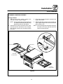
Oven Assembly
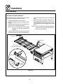
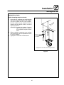
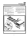
STANDARD CONVEYOR ASSEMBLY
Conveyor Racks
1. Slide the drive side conveyor support rack
onto the conveyor support angles.
NOTE: The sprocket on the conveyor rack must
be inside th e elect ric a l box af te r being
pushed into the oven. See View A.
2. Install the drive chain around the drive motor
sprocket and the sprocket on the conveyor
rack. Pull the conveyor rack forward to tighten
the chain.
3. Securetheconveyorusingtheconveyorlocat-
ing pin. See View A.
4. Slide the idle side conveyor rack onto the con-
veyor support angles until it touches the drive
side conveyor rack.
NOTE: If the mounting hole cannot be lined up or
the chain is too loose, the drive motor will
need to be repositioned.
Drive Side
Conveyor Rack
Idle Side
Conveyor Rack
See View A
See View A
View A
Sprocket
Locating
Pin
Conveyor
Bracket
Figure 9

Installation
14
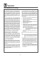
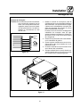
Oven Assembly
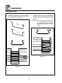
Conveyor Belt
NOTE: The following directio n s are writt en for left to
right trave l. For right to left trave l, th re ad th e
belt fro m th e le ft side of th e oven . The t wo
ends will meet on the right side of the oven.
Direction of
Travel
Belt Top
Figure 10
1. Thread the conveyor belt from the right side of
the oven. The conveyor belt has loops on both
ends. The loops must travel backwards on the
conveyor rack to prevent belt damage. See
Figure 11 for proper belt orientation.
Push the belt through the conveyor rack
threading in between the top and bottom
guide rods. Stop when there is approximately
12” (31 cm) of belt hanging out on the left side.
2. Thread the belt around the sprockets on the
left conveyor rack.
3. Take the remainder of the belt, loo p it around the
sprockets o n the right convey or rack.
4. Push the remainder of the belt through the
oven cavity on top of the conveyor racks.
5. Each end of the belt shoul d meet approxim ately
6” (15 cm) past the end of the left conveyo r rack.
Figure 11

Installation
15
Oven Assembly
6. Install the inner master links to connect the
two ends of the conveyor belt. See Figure 12.
Upside-down
Proper
Position
InnerMasterLink
Figure 12
7. Install the outer master links to finish connect -
ing the tw o ends of the conveyor belt. See
Figure 13.
NOTE: The extra piece of wire belt can be used to
make additional master links if the original
links are lost or damaged.
Outer Master Link
Figure 13

Installation
16
Oven Assembly
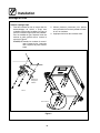
OPTIONAL FOLDING CONVEYOR
The folding conveyor assembly must be installed
from the electrical box side of the oven.
1. Unfold the right side of the conveyor.
2. Push the conveyor onto the conveyor support
angles.
3. Unfoldtheleftsideoftheconveyorandcontin-
ue to push onto the support angles.
NOTE: Push until the sprocket on the fo lding
con v e y o r is inside the elect ric a l box.
See View A.
4. Install the drive chain around the drive motor
sprocket and the sprocket on the folding con-
veyor. Pull the folding conveyor to tighten the
chain.
5. Secure the folding conveyor using the con -
veyor locating pin. Install the pin from the in-
side of the electrical box, through the convey-
or bracket and into the folding conveyor. See
View A.
NOTE: If the mounting hole cannot be lined up or
the chain is too loose, the drive motor will
need to be repositioned.
Folding Conveyor
(shown without belt for clarity)
See View A
See View A
View A
Sprocket
Locating
Pin
Conveyor
Bracket
Figure 14

Installation
17
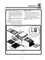
Oven Assembly
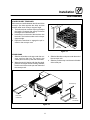
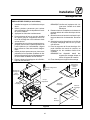
CONVEYOR BELT TENSIONER
Each tensioner installs betw een the idle end of the
conveyor (the side opposite the drive) and the
bracket under each conveyor support angle.
1. The belt tensioner contains a spring to a dj ust
the length. Compress the spring to shorten
the length of t he belt tensioner.
2. Insert the pin on the end of the tensioner into
the hole in the bracket under each conveyor
support angle.
3. Expand the tensioner to engage the pin lo-
cated on the conveyor rack.
Belt
Tensioner
Figure 15
CRUMB PANS
1. Slidethedrivesidecrumbpanunderthecon-
veyor rack from the front. The notch in the
crumb pan must line up with the drive shaft.
2. When the notch is lined up with the drive shaft,
push the crumb pan into the cooking chamber.
Hook the end of the crumb pan over the end of
theconveyorrack.
3. Slide the idle side crumb pan under the end of
theconveyorrack.
4. Slide the product stop over the end of the idle
side crumb pan.
Drive Side
Crumb Pan
Idle Side
Crumb Pan
Notch
Product Stop
Figure 16
Page is loading ...
Page is loading ...
Page is loading ...
Page is loading ...
Page is loading ...
Page is loading ...
Page is loading ...
Page is loading ...
Page is loading ...
Page is loading ...
Page is loading ...
Page is loading ...
Page is loading ...
Page is loading ...
Page is loading ...
Page is loading ...
Page is loading ...
Page is loading ...
Page is loading ...
Page is loading ...
Page is loading ...
Page is loading ...
Page is loading ...
Page is loading ...
Page is loading ...
Page is loading ...
Page is loading ...
Page is loading ...
Page is loading ...
Page is loading ...
Page is loading ...
Page is loading ...
Page is loading ...
Page is loading ...
Page is loading ...
Page is loading ...
Page is loading ...
Page is loading ...
Page is loading ...
Page is loading ...
Page is loading ...
Page is loading ...
Page is loading ...
Page is loading ...
Page is loading ...
Page is loading ...
Page is loading ...
Page is loading ...
Page is loading ...
Page is loading ...
Page is loading ...
Page is loading ...
Page is loading ...
Page is loading ...
Page is loading ...
Page is loading ...
Page is loading ...
Page is loading ...
Page is loading ...
Page is loading ...
-
 1
1
-
 2
2
-
 3
3
-
 4
4
-
 5
5
-
 6
6
-
 7
7
-
 8
8
-
 9
9
-
 10
10
-
 11
11
-
 12
12
-
 13
13
-
 14
14
-
 15
15
-
 16
16
-
 17
17
-
 18
18
-
 19
19
-
 20
20
-
 21
21
-
 22
22
-
 23
23
-
 24
24
-
 25
25
-
 26
26
-
 27
27
-
 28
28
-
 29
29
-
 30
30
-
 31
31
-
 32
32
-
 33
33
-
 34
34
-
 35
35
-
 36
36
-
 37
37
-
 38
38
-
 39
39
-
 40
40
-
 41
41
-
 42
42
-
 43
43
-
 44
44
-
 45
45
-
 46
46
-
 47
47
-
 48
48
-
 49
49
-
 50
50
-
 51
51
-
 52
52
-
 53
53
-
 54
54
-
 55
55
-
 56
56
-
 57
57
-
 58
58
-
 59
59
-
 60
60
-
 61
61
-
 62
62
-
 63
63
-
 64
64
-
 65
65
-
 66
66
-
 67
67
-
 68
68
-
 69
69
-
 70
70
-
 71
71
-
 72
72
-
 73
73
-
 74
74
-
 75
75
-
 76
76
-
 77
77
-
 78
78
-
 79
79
-
 80
80
-
 81
81


Blodgett SG3240E Operating instructions
- Category
- Ovens
- Type
- Operating instructions
- This manual is also suitable for
Ask a question and I''ll find the answer in the document
Finding information in a document is now easier with AI
in other languages
- français: Blodgett SG3240E Mode d'emploi
Related papers
-
Blodgett MT3240G Operating instructions
-
Blodgett MT1820E User manual
-
-
-
-
-
-
-
-
Other documents
-
 AMTI Products SHRINK Quick start guide
-
 Bakers Pride VH-1828G-1 Operating instructions
-
Bartscher 2002200 Operating instructions
-
Middleby Marshall PS500 User manual
-
-
-
Star Manufacturing UM1854-NATCE Operating instructions
-
-
-
Middleby PS220VL User manual

