Page is loading ...

©2005 Middleby Marshall Inc.
MiddlebyMiddleby
MiddlebyMiddleby
Middleby
MarshallMarshall
MarshallMarshall
Marshall
A MIDDLEBY COMPANY
PS536-Series Electric Ovens: English
owner's
operating
& installation
manual
PS536-Series
OVENS
Model
PS536ES
PS536ES (Triple)
PS536ES (Double)
Part No. 58367
Price $30.00
P: 08/08 Rev. B
®
PS536ES (Single)

ii
WARNING
FOR YOUR SAFETY, DO NOT STORE OR USE
GASOLINE OR OTHER FLAMMABLE VAPORS AND
LIQUIDS IN THE VICINITY OF THIS OR ANY OTHER
APPLIANCE.
WARNING
Improper installation, adjustment, alteration, service, or
maintenance can cause property damage, injury, or
death. Read the installation, operation, and maintenance
instructions thoroughly before installing or servicing this
equipment.
NOTICE
The warranty is
NOT VALID
unless the oven is installed, started, and
demonstrated under the supervision of a factory-authorized installer.
NOTICE
Contact your authorized Service Agency to perform maintenance and
repairs. A Service Agency Directory is supplied with your oven.
NOTICE
Using any parts other than genuine Middleby Marshall factory-manufactured
parts relieves the manufacturer of all warranty and liability.
NOTICE
Middleby Marshall (Manufacturer) reserves the right to
change specifications at any time.
KEEP THIS MANUAL IN A VISIBLE LOCATION NEAR THE OVEN
FOR FUTURE REFERENCE.

iii
MIDDLEBY MARSHALL INC.
OVEN LIMITED WARRANTY
(Non U.S.A.)
The Seller warrants equipment manufactured by it to be free from
defects in material and workmanship for which it is responsible. The
Seller’s obligation under this warranty shall be limited to replacing or
repairing, at Seller’s option, without charge, F.O.B. Seller’s factory,
any part found to be defective and any labor and material expense
incurred by Seller in repairing or replacing such part. Such warranty
is limited to a period of one year from date of original installation or
15 months from date of shipment from Seller’s factory, whichever is
earlier, provided that terms of payment have been fully met. All labor
shall be performed during regular working hours. Overtime premium
will be charged to the Buyer.
This warranty is not valid unless equipment is installed, started,
and demonstrated under the supervision of a factory-autho-
rized installer.
Normal maintenance functions, including lubrication, adjustment of
airflow, thermostats, door mechanisms, microswitches, burners
and pilot burners, and replacement of light bulbs, fuses and indicat-
ing lights, are not covered by warranty.
Any repairs or replacements of defective parts shall be performed by
Seller’s authorized service personnel. Seller shall not be respon-
sible for any costs incurred if the work is performed by other than
Seller’s authorized service personnel.
When returning any part under warranty, the part must be intact and
complete, without evidence of misuse or abuse, freight prepaid.
Seller shall not be liable for consequential damages of any kind
which occur during the course of installation of equipment, or which
result from the use or misuse by Buyer, its employees or others of
the equipment supplied hereunder, and Buyer’s sole and exclusive
remedy against Seller for any breach of the foregoing warranty or
otherwise shall be for the repair or replacement of the equipment or
parts thereof affected by such breach.
The foregoing warranty shall be valid and binding upon Seller if and
only if Buyer loads, operates and maintains the equipment supplied
hereunder in accordance with the instruction manual provided to
Buyer. Seller does not guarantee the process of manufacture by
Buyer or the quality of product to be produced by the equipment
supplied hereunder and Seller shall not be liable for any prospective
or lost profits of Buyer.
THE FOREGOING WARRANTY IS EXCLUSIVE AND IN LIEU OF
ALL OTHER EXPRESS AND IMPLIED WARRANTIES WHATSO-
EVER. SPECIFICALLY THERE ARE NO IMPLIED WARRANTIES
OF MERCHANTABILITY OR OF FITNESS FOR A PARTICULAR
PURPOSE.
The foregoing shall be Seller’s sole and exclusive obligation and
Buyer’s sole and exclusive remedy for any action, whether in breach
of contract or negligence. In no event shall seller be liable for a sum
in excess of the purchase price of the item.
Model No.
Modéle No.
Serial No.
Serié No.
Installation Date
Date d'installation
MIDDLEBY MARSHALL
N
O QUIBBLE LIMITED WARRANTY
(U.S.A. ONLY)
MIDDLEBY MARSHALL, HEREINAFTER REFERRED TO AS
“THE SELLER”, WARRANTS EQUIPMENT MANUFACTURED
BY IT TO BE FREE FROM DEFECTS IN MATERIAL AND
WORKMANSHIP FOR WHICH IT IS RESPONSIBLE. THE
SELLER’S OBLIGATION UNDER THIS WARRANTY SHALL
BE LIMITED TO REPLACING OR REPAIRING, AT SELLER’S
OPTION, WITHOUT CHARGE, ANY PART FOUND TO BE
DEFECTIVE AND ANY LABOR AND MATERIAL EXPENSE
INCURRED BY SELLER IN REPAIRING OR REPLACING
SUCH PART. SUCH WARRANTY SHALL BE LIMITED TO
THE ORIGINAL PURCHASER ONLY AND SHALL BE EFFEC-
TIVE FOR A PERIOD OF ONE YEAR FROM DATE OF ORIGI-
NAL INSTALLATION, OR 18 MONTHS FROM DATE OF PUR-
CHASE, WHICHEVER IS EARLIER, PROVIDED THAT TERMS
OF PAYMENT HAVE BEEN FULLY MET.
This warranty is valid only if the equipment is installed, started,
and demonstrated under the supervision of a factory-autho-
rized installer.
Normal maintenance functions, including lubrication, clean-
ing, or customer abuse, are not covered by this
no quibble
warranty
.
Seller shall be responsible only for repairs or replacements
of defective parts performed by Seller’s authorized service
personnel. Authorized service agencies are located in prin-
cipal cities throughout the contiguous United States, Alaska,
and Hawaii. This warranty is valid in the 50 United States
and is void elsewhere unless the product is purchased
through Middleby International with warranty included.
The foregoing warranty is exclusive and in lieu of all other
warranties, expressed or implied. There are no implied
warranties of merchantability or of fitness for a particu-
lar purpose.
The foregoing shall be Seller’s sole and exclusive obligation
and Buyer’s sole and exclusive remedy for any action, in-
cluding breach of contract or negligence. In no event shall
Seller be liable for a sum in excess of the purchase price of
the item. Seller shall not be liable for any prospective or lost
profits of Buyer.
This warranty is effective on Middleby Marshall equip-
ment sold on, or after, February 15, 1995.
© 2005 - Middleby Marshall, A Middleby Company.
The Middleby Marshall logo is a registered trademark of Middleby Marshall, A Middleby Company.
Middleby Marshall Inc. • 1400 Toastmaster Drive • Elgin, Illinois 60120-9272 U.S.A. • (847) 741-3300 • FAX: (847) 741 4406

iv
NOTE
Wiring Diagrams are in Section 7 of this Manual.
The diagram for each oven is also on the lower
inner surface of its Control Console.
TABLE OF CONTENTS
Page
SECTION 1
I. MODEL IDENTIFICATION .............................................. 1
SERIES PS536 ELECTRICAL SPECIFICATIONS............. 2
II. PRINCIPLE OF AIR FLOW............................................. 3
A. Heat Transfer and How It Works .............................. 3
II. PRINCIPLE OF AIR FLOW (Continued) ........................ 4
B. Air Fingers ................................................................. 4
III. COMPONENT FUNCTION ............................................ 5
A. Conveyor Motor and Conveyor Belt ........................ 6
B. Blower Fan ................................................................. 6
C. Electric Heaters ........................................................ 6
D. Window ....................................................................... 6
E. Cooling Fan ................................................................ 7
F. Air Fingers and Blank Plates - See Figure 1-9......... 8
SECTION 2
I. UNLOADING ................................................................... 9
PS536 OVEN INSTALLATION
REQUIRED KITS AND EQUIPMENT........................ 10
PARTS LIST FOR SERIES PS536 ELECTRIC OVEN
INSTALLATION KIT .................................................. 10
PARTS LIST FOR PS536 SERIES SINGLE OVEN
OPTION - BASE W/15
″″
″″
″ LEGS & TOP P/N 34832 ..... 11
PARTS LIST FOR PS536 SERIES DOUBLE OVEN
OPTION - BASE W/6
″″
″″
″ LEGS,
CASTERS & TOP P/N 34833.................................... 12
PARTS LIST FOR PS536 SERIES TRIPLE OVEN
OPTION - BASE w/OUTRIGGERS & TOP
P/N 34831................................................................... 13
RESTRAINT CABLE INSTALLATION.......................... 16
UTILITY ROUGH-IN DIMENSIONS AND POSITIONING
FOR PS536-SERIES OVENS.................................... 17
CIRCUIT BREAKER ..................................................... 17
ELECTRICAL SPECIFICATIONS ................................. 17
ELECTRICAL RATING ................................................. 17
SUPPLY WIRE .............................................................. 17
SUGGESTED ................................................................ 17
II. VENTILATION GUIDELINES .......................................18
VENTILATION HOOD ................................................... 18
VENTILATION CAPTURE TEST................................... 18
III. ELECTRICAL CONNECTION INFORMATION FOR
PS536-SERIES OVENS. ........................................... 19
IV. ELECTRIC SUPPLY FOR ELECTRIC-HEATED
OVENS....................................................................... 19
VI. CONVEYOR REAR STOP AND
END STOP INSTALLATION ...................................... 20
SECTION 3 INSTALLATION
I. CONTROL FUNCTIONS ................................................ 21
II. COMPONENT INFORMATION AND LOCATION......... 22
A. Door Safety Switch.................................................. 22
B. Blower Switch .......................................................... 22
C. Heat Switch .............................................................. 22
D. Temperature Controller .......................................... 22
E. Conveyor ................................................................. 23
MEASURING CONVEYOR SPEED. ............................. 23
III. STEP-BY-STEP OPERATION..................................... 24
A. Startup Procedures................................................. 24
TABLE OF CONTENTS
(Continued)
Page
Daily Startup................................................................. 24
Power Failure ............................................................... 24
B. Shutdown Procedure............................................... 24
A.Daily Startup Procedure .......................................... 26
IV. NORMAL OPERATION - STEP-BY-STEP .................. 26
V. QUICK REFERENCE: TROUBLESHOOTING............. 28
SECTION 4 MAINTENANCE
I. MAINTENANCE - DAILY ........................................... 30
A. Exterior .................................................................... 30
B. Cooling Fan .............................................................. 30
C. Conveyor Belt......................................................... 30
D. Crumb Pans ............................................................ 30
E. Window .................................................................... 30
II. MAINTENANCE - MONTHLY ...................................... 31
A. Removing Conveyor From Oven For Cleaning .... 31
B. Air Fingers Disassembly For Cleaning................. 33
C. Cleaning the Window .............................................. 34
D. Reassembly of Air Fingers .................................... 34
E. Reinstall End Plugs ................................................. 37
F. Conveyor Reassembly Into Oven.......................... 38
G. Checking Conveyor Belt Tension ......................... 38
H. Conveyor Belt Link Removal ................................ 39
I. Replacing Conveyor Belt......................................... 40
J. Attaching Drive Chain ............................................ 40
III. MAINTENANCE - EVERY 3 MONTHS ........................ 41
A. Cleaning the Blower/Fan Motor ............................. 41
B. Electrical Terminals ............................................... 42
C. Ventilation ............................................................... 42
D. Checking the Blower/Fan Belt ............................... 42
E. Blower Fan Shaft Bearing Lubrication .................. 43
F. Split-belt Conveyor Shaft Cleaning ........................ 43
IV. MAINTENANCE - EVERY 6 MONTHS .................... 44
PS540-SERIES ELECTRIC OVEN KEY SPARE
PARTS ....................................................................... 46
KEY SPARE PARTS KIT ..............................................46
SECTION 5 TROUBLESHOOTING
Troubleshooting Charts ..................................................... 47
SECTION 6 - PARTS LIST
OVEN PANELS, WINDOW AND LEGS............................ 51
CONTROL PANEL ........................................................... 53
BLOWER AND SHROUD................................................. 55
CONVEYOR...................................................................... 57
SPLIT BELT CONVEYOR................................................. 59
MACHINERY COMPARTMENT....................................... 61
SECTION 7 ELECTRICAL SCHEMATICS
Wiring Diagram, E208-240 50/60, 3PH 4W PS536 ........ 63
Wiring Diagram, E380-480 50/60, 3PH 5W PS536 ........ 64
Wiring Diagram, E380V 50/60, 3PH 5W PS536.............. 65

SECTION 1
DESCRIPTION
1
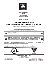
I. MODEL IDENTIFICATION
The Middleby Marshall PS536ES-Series may be used
either as a single oven or stacked for use as double or triple
ovens.
The major difference between the oven models in
this series is the width of the conveyor.
A single PS536ES-Series Oven (Figure 1-1) is mounted on
a base pad with legs and casters. A double oven (Figure 1-
2) consists of two,
stacked,
single ovens. A triple oven
(Figure 1-3) consists of three stacked single ovens. The
lower oven is mounted on a base pad with short legs and
casters.
On a double or triple oven, the ovens operate completely
independent. All ovens use identical controls and compo-
nents. One oven can be cleaned or serviced, while the
others are operating.
SECTION 1
DESCRIPTION
Figure 1-1. Single PS536ES Oven
Figure 1-2. Double PS536ES Oven
Figure 1-3. Triple PS536ES Oven

2
SECTION 1
DESCRIPTION
PS536ES SERIES OVEN SPECIFICATIONS
Table 1-1: Dimensions
Overall Height:
single oven with 17-1/2" (446mm) legs 43-1/2" (1105mm)
double oven with standard 17-1/2" (446mm) legs 63" (1600mm)
double oven with optional 20-1/2" (521mm) legs 66" (1676mm)
double oven with optional 25-1/2" (648mm) legs 71" (1803mm)
triple oven with 6" (152mm) legs 71" (1803mm)
Overall Depth:
46" (1168mm)
Overall Length:
with standard 60"/1524mm conveyor 61" (1549mm)
with optional 56"/1422mm conveyor 57" (1447mm)
with optional 76"/1930mm conveyor 77" (1956mm)
Baking Chamber Length
36" (914mm)
Conveyor Width:
Single Belt 20" (508mm)
Split Belt 2 x 9-1/2" (241mm)
Conveyor Length
56" (1422mm) or 60" (1524mm) or 76" (1930mm)
Recommended Minimum Clearances:
Rear of oven to wall 3" (76mm)
Control end of conveyor to wall 1" (25.4mm)
Non-control end of oven to wall 1" (25.4mm)
Table 1-2: General specifications (per oven cavity)
Weight
400 lbs. (182kg)
Rated Heat Input:
17 kW/hr.
Maximum Operating Temperature
550°F (288°C)
Warmup Time
25 minutes
SERIES PS536ES ELECTRICAL SPECIFICATIONS
Main Blower & Control Circuit Phase Frequency Amperage Poles Wires
Elements Voltage Voltage Draw
208-240V 208-240V 3 Ph 50/60 Hz 60 Amp 4 Pole 4 Wire
(3 hot, 1 grd)
HEATER AMPERAGE
Voltage kW L1
208 27 75
240 27 65
380-400V 208-240V 3 Ph 50/60 Hz 60 Amp 4 Pole 5 Wire
(3 hot, 1neut, 1 grd)
HEATER AMPERAGE
Voltage kW Amp
380-400 27-29.9 40-44
400V 208-240V 3 Ph 50/60 Hz 60 Amp 4 Pole 5 Wire
(3 hot, 1neut, 1 grd)
HEATER AMPERAGE
Voltage kW Amp
400 27 32.5
Voltage kW L1 L2 L3
208 17 49.4 49.4 47.2
240 17 42.1 42.1 40.9
NOTE
Wiring Diagrams are contained in Section 7 of this Manual
and are also located inside the oven at the
bottom of the Control Panel
This Manual Must Be Kept For Future Reference
AMPERAGE
Voltage kW L1 L2 L3 N
380-400 17-18.8 27.0-29.8 25.8-28.6 25.8-28.6 1.2
Voltage kW L1 L2 L3 N
480 17 21.6 20.4 20.4 1.2

SECTION 1
DESCRIPTION
3
II. PRINCIPLE OF AIR FLOW
The fan-style blower draws air into the oven plenum where
it is heated. The blower then pushes the hot air through the
air fingers into the baking chamber. Each air finger
contains an inner plate and outer plate that form the hot air
into jets, distributing it across a conveyor belt on which the
food product rides. Air is then pulled back into the blower
and the process continues. The curving, black arrows of
Figure 1-4 show this air flow.
A. Heat Transfer and How It Works
1. Heat constantly moves from a warm object to a cold
object. Heat moves using three different paths: Conduc-
tion; Radiation; and Convection.
Conduction:
This path utilizes surface-to-surface con-
tact. The pizza dough in contact with the pan is a good
example of conduction.
Radiation:
This path has to do with objects radiating heat.
Dark objects absorb heat whereas light or shiny objects
reflect more heat. This is the reason that the inside of a
PS536ES-Series Oven is light in color: To reflect more
heat back onto the food product.
Convection:
This path has to do with moving a volume of
air. It explains why hot air rises and cooler air replaces hot
air. An industrial application of this principle is to incorpo-
rate a fan to force the hot air movement, which in turn
increases the heat transfer to the food product.
Each PS536ES-Series Oven has a large fan-style blower
to move the hot air through the air fingers and onto the
product to cook/bake the food product most efficiently.
2. Temperature is the intensity of heat at the point where
it is sensed. As discussed above, heat flows by conduc-
tion, radiation and convection. The speed at which the heat
flows is determined by the temperature difference between
the oven and the food product. The larger the difference,
the faster the heat flows to the item that is being baked.
Upper Air Fingers
Lower Air Fingers
Conveyor Belt(s)
Window
Figure 1-4. PS536ES-Series Oven Air Flow

4
SECTION 1
DESCRIPTION
Series ovens used to bake pizza have four bottom fingers
and two top fingers. For special product baking require-
ments, a number of other styles of fingers and finger
arrangements are available from the factory.
NOTE:
Some customers have a predetermined finger
arrangement. If you have any questions pertaining to the
finger arrangement, please call the factory.
Air Flow
From Plenum
Manifold
Manifold Baffle
Outer Plate
Inner Plate
Air Flow
From Plenum
Manifold
Manifold Baffle
Outer Plate
Inner Plate
High Velocity
Columns of Air
on Food Product
II. PRINCIPLE OF AIR FLOW (Continued)
B. Air Fingers
The PS536ES-Series Ovens are conveyorized ovens that
employ vertical jets of hot air streaming from air fingers
(Figure 1-5) to give uniform, intense heating. The vertical
streams of hot air provide an exceptional heat transfer rate
and generally bake faster and at lower temperatures than
convection hot air or infrared heating ovens.
A PS536ES-Series Oven can accommodate up to four
bottom air fingers and four top air fingers. Some PS536ES-
Figure 1-5. Air Fingers, Showing High-Velocity Columns of Air Formed During Passage Through
the Inner Plate and Outer Plate to Heat the Food Product.

SECTION 1
DESCRIPTION
5
III. COMPONENT FUNCTION (Figure 1-6)
Figure 1-6. PS536ES-Series Oven Components Locations

6
SECTION 1
DESCRIPTION
III. COMPONENT FUNCTION
A. Conveyor Motor and Conveyor Belt
The conveyor belt is driven by a variable-speed electric
motor (Figure 1-7) operating through a gear reducer. The
motor speed is controlled by a digital control. The stain-
less-steel wire belt can travel in either direction at variable
rates ranging from 3 minutes to 30 minutes; this is the time
that a product can take to pass through the oven.
B. Blower Fan
The blower fan is located at the rear of the oven. This
blower forces heated air through the air fingers. The
BLOWER/Heat switch must be set to “ON” or “I” for oven
warmup and baking.
C. Electric Heaters
There is one heater element mounted on the inside of the
left panel. The element is connected to an electrical
control which is energized by the temperature controller.
If the pilot flame does not light or a loss of flame occurs,
the main gas valve closes.
The main burner gas is extinguished when the HEAT
switch is set to “OFF” or “O”.
D. Window
A window on the front of the oven permits viewing the items
being baked and provides access to the oven for items that
do not require full baking time, such as sandwiches,
cookies, small items, or cheese-melting processes.
E. Cooling Fan — See Figure 1-8
The cooling fans are located in the back of the oven.
These cooling fans draw air through its grille, blowing it
through the blower motor compartment and the control
compartment into the oven top and exhausted out the front
louvers.
F. Air Fingers and Blank Plates - See Figure 1-9
F1. Air Fingers
An Air Finger Assembly is made up of three parts:
1. Outer Plate - The Outer Plate is the removable covering
with tapered holes, which direct the air stream onto the
product being baked.
2. Inner Plate -The perforated Inner Plate is vital in forming
the unique air jets. It must be assembled into the manifold
with its holes aligned with the holes of the outer plate.
3. Manifold - The Manifold is the assembly which slides
on tracks into the oven plenum.
Figure 1-7. Machinery Compartment
Components

SECTION 1
DESCRIPTION
7
Figure 1-8. Cooling Fan

8
SECTION 1
DESCRIPTION
Half Blank Plate
Blank Plate
Outer Plate
Inner Plate
Finger
Manifold
Assembly
Baffle
Figure 1-9. Blank Plates (two sizes) and an Air Finger.
F2. Blank Plates
1. Blank Plates- The Blank Plates are available to install
on the plenum where an air finger is not required.

SECTION 2
INSTALLATION
9
SECTION 2
INSTALLATION
NOTE: The oven, when installed, must be electrically
grounded in accordance with local codes, or in the ab-
sence of local codes, with the National Electrical Code
(NEC), or ANSI/NFPA70.
NOTE
There must be adequate clearance between
the oven and any adjacent combustible con-
struction. Clearance must also be provided
for servicing and for operation.
CAUTION
It is required that the oven be placed under a
ventilation hood for adequate air supply and
ventilation.
CAUTION
Do not obstruct the flow of combustion and
ventilation air to and from your oven. Do not
obstruct the ventilation holes in the Control Panel.
CAUTION
On ovens with the Machinery Drive Compartment
located at the right end, a minimum clearance of
0″ to a left side wall, 18″ to a right side wall and 6″
from a back wall to air openings at the rear of the
oven must be maintained. On ovens with the
machinery/drive compartment located at the left
end, a minimum clearance of 0″ to a right side
wall, 18″ to a left side wall and 6″ from a back wall
to air openings at the rear of the oven must be
maintained.
For servicing and cleaning, a minimum of 18″
clearance from all walls is recommended.
I. UNLOADING
Your Middleby Marshall PS536ES-Series Oven is shipped
partially assembled. It will arrive in a carton on a crate.
Carton size for a PS540-Series Oven is:
58″ (2134mm) Long ×
47.25″ (1473mm) Wide ×
36″ (1118mm) High ×
The crate and carton must be examined before signing the
Bill of Lading. Report any visible damage to the transport
company, and check for the proper number of crates. If
apparent damage is found, make arrangements to file a
claim against the carrier. Surface Interstate Commerce
Regulations (U.S.A.) require that the claim must be
initiated by the consignee within 10 days from the date that
the shipment is received.
A Pre-installation Procedures Manual (MM P/N 88910-0009)
is attached to the exterior wall of the carton. This manual
contains detailed instructions on unpacking and moving the
oven(s) to the operating site. When the transport company
notifies you of an impending delivery, arrange to have a forklift
at your facility to unload the carton(s).
Instructions for stacking the ovens is continued in a
separate manual used by Middleby Marshall Authorized
Installers.
If you have a door wider than the carton, simply move the
carton into your facility and arrange an appointment with
your Middleby Marshall Authorized Installer.
If your door is narrower than the carton, then the oven will
have to be unpacked. Follow the directions shown in the
Pre-Installation Procedures Manual.

10
SECTION 2
INSTALLATION
PS536ES OVEN INSTALLATION
REQUIRED KITS AND EQUIPMENT
TYPE PS536ES PS536ES PS536ES PS536ES
OF Single Oven Double Oven Triple Oven Additional Cavity
INSTALLATION Installation Installation Installation Installation
Kit P/N Kit P/N Kit P/N Kit P/N
44919 44920 44921 44974
45529 (CE) 45530 (CE) 45531 (CE) 45532 (CE)
PS536ES Single Oven 1 1
PS536ES Double Oven 1 2
PS536ES Triple Oven 1 3

SECTION 2
INSTALLATION
11
Figure 2-1 - Installation Kit
I. INSTALLATION KIT - see Figure 2-1
Qty. Qty. Qty. Inc. with Inc. with
Single Double Triple domestic CE
Item Oven Oven Oven Part No. ovens? ovens? Description
1 1 1 1 48605 Yes Yes Top panel
2 2 2 2 3A80A8801 Yes Yes Screw, pan head #10 x 2″
3 1 1 1 42893 Yes Yes Base pad
4a 4 4 -- 42890 Yes Yes 17-1/2″ (445mm) leg extension, for single and
double ovens
4b -- 4 -- 45360 Yes Yes 20-1/2″ (521mm) leg extension, optional
4c -- 4 -- 45329 Yes Yes 25-1/2″ (648mm) leg extension, optional
4d -- -- 4 44799 Yes Yes 6″ (152mm) leg extension, for triple ovens only
5 2 2 2 22290-0009 Yes Yes Caster, with flat plate and brake
6 2 2 2 22290-0010 Yes Yes Caster, with flat plate (no brake)
NOTE:
Domestic and standard export ovens include 2 braking casters (item 5) and 2 non-braking casters (Item 6). CE-approved
ovens include 4 non-braking casters (Item 6) SOLELY for the purpose of moving the oven to the installation location. Casters are
NOT suitable for use as part of CE oven installations. Refer to the notice on the preceding page.
7 4 4 4 22450-0028 No No Leg, adjustable, 6″ (152mm)
8 1 1 1 21392-0004 Yes Yes Eyebolt, 3/4″
9 A/R A/R A/R 220373 Yes Yes Hex bolt, 3/8″-16 x 1″
NOTE:
CE-approved ovens include 32 hex bolts. Domestic and standard export ovens include 31 hex bolts and one eyebolt (item 8)
that acts as an anchor for the restraint cable (Item 12). CE ovens are mounted on legs (Item 7) and do not use a restraint cable.
10 32 32 32 21416-0001 Yes Yes Flat washer, 3/8″
11 32 32 32 21422-0001 Yes Yes Lockwasher, 3/8″
12 1 1 1 22450-0228 Yes Yes Restraint cable assembly
13 1 1 1 50236 Yes Yes
Owner's Operating and Installation Manual
14 1 1 1 1002040 Yes Yes
Authorized Service Agency Listing
15 1 1 -- 46393 Yes Yes Lower shelf

12
SECTION 2
INSTALLATION
Figure 2-5. MODEL PS536ES SINGLE OVEN DIMENSIONS
ELECTRICAL JUNCTION BOX
RECOMMENDED MINIMUM CLEARANCES:
Rear of Oven to Wall - 6″ (150mm)
Non-control End of Oven to Wall - 0″
Control End of Oven to Wall - 0″
1
2
2
2
2
1

SECTION 2
INSTALLATION
13
Figure 2-6. MODEL PS536ES DOUBLE OVEN DIMENSIONS
ELECTRICAL JUNCTION BOX
RECOMMENDED MINIMUM CLEARANCES:
Rear of Oven to Wall - 6″ (150mm)
Non-control End of Oven to Wall - 0″
Control End of Oven to Wall - 0″
1
2
2
2
2
1

14
SECTION 2
INSTALLATION
RESTRAINT CABLE INSTALLATION
Install the restraint cable assembly on the oven, as shown
in Figure 2-6.
Figure 2-7. MODEL PS536ES TRIPLE OVEN DIMENSIONS
ELECTRICAL JUNCTION BOX
RECOMMENDED MINIMUM CLEARANCES:
Rear of Oven to Wall - 6″ (150mm)
Non-control End of Oven to Wall - 0″
Control End of Oven to Wall - 0″
Figure 2-8. Restraint Cable Assembly Installation
1
2
2
2
2
1

SECTION 2
INSTALLATION
15
WARNING
DO NOT USE CONDUIT OR GAS LINE
FOR GROUND CONNECTION.
CAUTION
IT IS REQUIRED THAT THE OVEN BE
PLACED UNDER A VENTILATION
HOOD FOR ADEQUATE AIR SUPPLY
AND VENTILATION.
ELECTRIC AND GAS SUPPLY TO BE
PROVIDED BY CUSTOMER
ELECTRICAL SAFETY SWITCH
15 Amp circuit breaker / fused disconnect switch with
lockout/tagout electrical shutoff for each oven. Wire
each oven separately.
ELECTRICAL SPECIFICATIONS
DOMESTIC or EXPORT: 208-240V blower motor,
1 phase, 4.1 Amp draw, 50/60 Hz, 208-240V control
circuit, 2 poles, 3-wire system per oven (2 hot, 1 grd).
Do
NOT
use conduit for ground.
GAS RATING
Model PS540 is 110,000 BTU/hour (27,720 kcal), 32.2 kW/hr.
MINIMUM GAS METER RATING
450 ft
3
/hour (12.6m
3
/h) for 1 or 2 ovens;
Add 180 cu. ft./hr (5.1 m
3
/h) for each additional oven.
Minimum rating does
not
take other gas appliances into
consideration. Gas consumption varies at each site. Total
BTU/hr (kcal/hr) must be calculated during high flame
operation for each appliance to determine if the meter
needs to be larger.
MINIMUM GAS PIPE SIZE
Natural: 2″ (51mm) ID for 1, 2, or 3 ovens with runs up
to 200 ft. (61m).
Must be a dedicated line.
Runs over 200 ft, (61m) consult factory.
Propane: 2 ″ (51mm) ID for 1, 2, or 3 ovens with runs up
to 200 ft. (61m).
Must be a dedicated line.
Runs over 200 ft, (61m) consult factory.
UTILITY ROUGH-IN DIMENSIONS AND POSITIONING
FOR PS540-SERIES OVENS
GAS SAFETY VALVE
A 3/4″ (19mm) ID (inner diameter) full-flow, gas shutoff
valve. A separate connection and valve must be provided
for each oven, as shown in Figure 2-9.
REQUIRED GAS SUPPLY PRESSURE
Natural: 6″ to 12″ water column (13.8 to 29.9 mbar)
Propane: 11.5″ to 12″ water column (28.7 to 29.9 mbar)
SUGGESTED
If space permits, electric and gas service should be
located near the control console end of the oven(s) to allow
convenient access to safety switches and valves.
USER SUPPLIED ITEMS (Figure 2-9)
ITEM DESCRIPTION
12″ (51mm) × 2″ (51mm) × 3/4″ (19mm) TEE
2 3/4″ (19mm) × 3″ (76mm) NIPPLE
3 3/4″ (19mm) FULL FLOW GAS SHUTOFF VALVE
42″ (51mm) × 3/4″ (19mm) 90° REDUCER ELBOW
52″ (51mm) ID GAS SUPPLY PIPE LINE - NATURAL GAS
6 15 AMP TOGGLE SWITCH - 2 POLE for GAS
Figure 2-9. Typical PS540-Series Oven(s)
Installation
24"
610mm
6
O
N
O
FF
13-1/2"
343mm
2
3
2
6
ON
O
FF
24"
610mm
2
3
2
27"
686mm
4
5
1
Suggested dimensions are shown; utility code
requirements supersede any factors shown.

16
SECTION 2
INSTALLATION
II. VENTILATION GUIDELINES
A mechanically driven ventilation system is required for
the PS536ES Series Middleby Marshall conveyorized
electric ovens. The minimum hood canopy dimensions are
outlined below.
Local codes and conditions vary greatly from one area to
another and must be complied with. Following are the
suggested requirements for good ventilation. Please re-
member these are recommendations or guidelines, you
may have a special condition or problem that will require
the services of a ventilation engineer or specialist. Proper
ventilation is the oven owner’s responsibility. Improper
ventilation can inhibit oven performance. It is recom-
mended that the ventilation and duct work be checked out
every three months. Grease filters in the intake of the hood
may be required by local codes.
VENTILATION HOOD
The rate of air flow exhausted through the ventilation
system is generally between 1400 and 2500 cu. ft./min.
(40 and 70 m
3
/min), but may vary depending on the oven
configuration and hood design. To avoid a negative
pressure condition in the kitchen area, return air must be
brought back to replenish the air that was exhausted. A
negative pressure in the kitchen can cause heat related
problems to the oven components as if there were no
ventilation at all. The best method of supplying return air
is through the heating, ventilation and air conditioning
system. Through they system, the air can be temperature
controlled for summer and winter. Return air can be
brought in directly from outside the building, but detrimen-
tal affects can result from either extreme seasonal hot and
cold temperature from the outdoors.
NOTE: Return air from fan driven system within the hood
must not blow at opening of bake chamber or poor oven
baking performance will result.
Figure 2-10. Vent Hood
/