Page is loading ...

BLODGETT OVEN COMPANY
www.blodgett.com
44 Lakeside Avenue, Burlington, Vermont 05401 USA Telephone (800) 331-5842, (802) 860-3700 Fax: (802)864-0183
PN 30930 Rev H (6/03)
E 2000 --- G.S. Blodgett Corporatio n
AC-500
CONVECTION OVEN
INSTALLATION -- OPERATION -- MAINTENANCE
AC-500
FOURS À CONVECTION
MANUEL D’INSTALLATION -- FONCTIONNEMENT -- ENTRETIEN

IMPORT
A
NT
FORYOURSAFETY
Do not store or use g asoline or other flammable vapors or liquids in the vicinity
of this or any other appliance.
AVERTIS SEMENT
Ne pas entreposer ni utiliser de l’essence ni d’autres vapeurs ou liquides inflam-
mables dans le vo is in a ge de cet appariel, ni de to u t au tre appareil.
INSTRUCTIONS TO BE FOLLOWED IN THE EVENT THE USER SMELLS GAS
MUST BE POSTED IN A PROMINENT LOCATION. THIS INFORMATION MAY BE
OBTAINED BY CONTACTING YOUR LOCAL GAS SUPPLIER.
LES INSTRUCTIONS À RESPECTER AU CAS OÙ L’UTILISATEUR PERÇOIT UNE
ODEUR DE GAZ DOIVENT ÊTRE AFFICHÉES DANS UN ENDROIT BIEN VISIBLE.
VOUS POUVEZ VOUS LES PROCURER AUPRÈS DE VOTRE FOURNISSEUR DE
GAZ LOCAL.
WA RN I N G: IMP RO P ER INSTALLATIO N , AD JUS TMEN T, ALTERATIO N , SERVIC E OR
MAI N TENA N C E CAN CAUSE PRO P ERTY DA MA GE, IN JURY OR DEATH. READ THE
INST ALLA TION, OPERA TING AND MAINTENANCE INSTRUCTIONS THOROUGHLY
BEFORE INSTALLING OR SERVICING THIS EQUIPMENT
A V ERTI SS EMENT: UNE INS TALLATION , UN AJUSTEMENT, UNE ALTÉRATIO N , UN
SERV I CE OU UN ENTRETIEN NON CON FO RME A UX NORMES PEUT CA US ER DES
DO MMA GES À LA PROPRI ÉTE, DES BLESSURES OU LA MORT. LIS EZ ATTENTIV E-
MENT LES DIREC TI V ES D’IN S TALLATION , D’OPÉRATI O N ET D’ ENTRETIEN AV A N T
DE FAIRE L’INS TALLATIO N OU L’ENTRETIEN DE CET ÉQUIP EMEN T.
The information contained in this manual i s important for the proper installation,
use, and maintenance of this oven. Adherence to these procedures and instruc-
tions will result in satisfactory baking results and long, trouble free service.
Please read this manual carefully and retain it for future reference.
Les informatio ns données dans le présent manuel sont importantes pour installer,
utiliser et entretenir cor r ect em ent ce fou r. Le respect de ces instructio n s et procé-
dures permettra d’obtenir de bons résultats de cuisso n et une longue durée de ser-
vice sans problèmes. Veuillez lire le présent manuel et le cons erver pour pouvoir
vou s y repor t er à l’avenir.
Errors: Descriptive, typographic or pictorial errors are subject to correction. Specifica-
tions are subject to change without notice.
Erreurs:Les erreurs de description, de typographie ou d’illustration font l’objet de
corrections. Les caractéristiques sont sujettes à modifications sans préavis.

Your Service Agency’s Address:
Adressedevotreagencedeservice:
Model/ Modèl:
Serial Number/Numéro de série:
Your oven was installed by/
Installateur de votre four:
Your oven’s installation was checked by/
Contrôleur de l’installation de votre four:

Table of Contents/Table des Matières
Introduction
Oven Description 2.....................
Oven Components 3....................
Installation
Delivery and Location 4.................
Oven Assembly 5......................
Leg A ttachment 5.....................
Caster Assembly 5....................
Double Section Assembly 6............
Oven Leveling 6......................
V entilation
Canopy Type Exhaust Hood 7..........
Direct Flue Arrangement 8.............
Utility Connections ---
Standards and Codes 9.................
Gas Connection 10......................
Electrical Connection 13.................
Initial Startup 14.........................
Operation
Safety In formation 15....................
CH-Pro3 (Solid State Programmable
Digital Control) 16.......................
Solid State Thermostat Control 19.........
How Cook and Hold Works 20............
General Guidelines for Operating
Personnel 21............................
Suggested Times and Temperatures 22....
Maintenance
Cleaning and Preventative Maintenance 23.
Troubleshooting Guide 24................
Introduction
DescriptionduFour 26...................
Éléments du Four 27.....................
Installation
Livraison et Implantation 28...............
Montage du Four 29.....................
Assemblage des Pieds 29...............
Montage des Roulettes 29..............
Montage de la Section Double 30........
MiseàNiveauduFour 30...............
V entilation 31...........................
Hotte D’évacuation Type Voûte 31.......
En Prise Directe 32.....................
Branchements de Service --- Normes et
Codes 33...............................
Branchement de Gaz 34.................
Raccordement Électrique 37..............
Mise en Marche Initiale 38................
Utilisation
Informations de Sécurité 39...............
CH-Pro3 (Commande numérique program-
mable pour semi-conducteurs) 40.........
Commandes à Semi-Conducteurs 44......
Principe de la Fonction de Cuisson
et Maintien 45...........................
Consignes Générales à l’Intention
des Utilasateurs 46......................
Durées et Températures Suggérées 47.....
Entretien
Nettoyage et Entretien Préventif 48........
GuidedeDétectiondesPannes 49........

Introduction
2
Oven Description
Cooking in a convection oven differs from cooking
in a conventional deck or range oven since heated
air is constantly recirculated over the product by
a fan in an enclosed chamber. The moving air con -
tinually strips away the layer of cool air s urround-
ing the product, quickly allowing the heat to pene-
trate. The result is a high quality product, cooked
at a lower temperature in a shorter amount of time.
Blodgett convection ovens represent the latest ad-
vancement in energy efficiency, reliability, and
ease of operation. Heat normally lost, is recircu -
lated within the cooking chamber before being
vented from the oven: resulting in substantial re-
ductions in energy consumption a nd enhanced
oven performance.
The Vertical Fired AC Series convection oven in -
corporates the latest advances in energy efficien-
cy, reliability and ease of operation. A unique com-
bination of superheated a ir and oven temperature
air, is accomplished by means of an induced back
draft blower wheel, which enhances oven perfor-
mance significantly. The enlarged cavity size pro -
motes improved air circulation and increased rack
capacity.
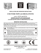
AirFlowPatternforAC-500
Direct Fired Convection Oven
Figure 1
Gas Specifications -- AC-500 gas oven
Natural Gas Propane Gas
US Units SI Units US Units SI Units
Heating V alue 1000 BTU/cu. ft. 37.3 MJ/m
3
2550 BTU/cu. ft. 95.0 MJ/m
3
Specific Gravity (air=1.0) 0.63 0.63 1.53 1.53
Gas Manifold Pressure 3.5” W.C. 0.87 kPa 10” W. C. 2.49 kPa
Oven Input 70,000 BTU/hr 20.5 kW 70,000 BTU/hr 20.5 kW
Main Burner Orifice Size 46 MTD* 2.1 mm 55 MTD* 1.32 mm
NOTE: *Multiple Twist Drill

Introduction
3
Oven Components
Combustion Cover --- provides access to the
combustion compartment on gas ovens.
Combustion Compartment --- contains combus-
tion burners on gas ovens.
Combustion Burners --- provide heat to the bak-
ing chamber on gas ovens.
Chain & Turnbuckle --- controls operation of the
oven doors.
Control Panel --- contains wiring andcomponents
to control the oven operation.
Oven Racks --- five racks are provided standard.
Additional racks are available.
Rack Supports --- hold ov en r a ck s .
Blo wer Wheel Cover --- located on the back interi-
or wall of the oven. Protects the blower wheel.
Blo wer Wheel --- spins to circulate hot air in the
baking chamber.
Convection Motor --- provides power t o turn the
blower wheel.
Oven Lights --- provide lighting inside the baking
compartment.
Rack
Rack Support
Figure 2

Installation
4
Delivery and Location
DELIVERY AND INSPECTION
All Blodgett ovens are shipped in containers to
prevent damage. Upon delivery of your new oven:
D
Inspect the shipping container for external dam-
age. Any evidence of damage should be noted
on the delivery receipt which must be signed by
the driver.
D
Uncrate the oven and check for internal dam-
age. Carriers will accept claims for concealed
damage if n otified within fifteen days of delivery
and the shipping container is retained for in-
spection.
The Blodgett Oven Company cannot assume
responsibility for loss or damage suffered in
transit. The carrier assumed full responsibility
for delivery in good order when the shipment
was accepted. We are, however, prepared to
assist you if filing a claim is necessary.
OVEN LOCATION
The well planned and proper placement of your
oven will result in long term operator convenience
and satisfactory performance.
The following clearances must be maintained be-
tween the oven and any combustible or non-com-
bustible construction.
D
Oven body right side --- 2” (5 cm)
D
Oven body left side --- 2” (5 cm)
D
Oven body back --- 2” (5 cm)
D
Oven body bottom --- 4” (10 cm)
The following clearances must be available for ser-
vicing.
D
Oven body sides --- 12” (30.5 cm)
D
Oven body back --- 12” (30.5 cm)
NOTE: Routine servicing can usually be accom-
plished within the limited movement pro-
vided by the gas hose restraint. If the oven
is moved further from the wall, the gas
must be turned off and disconnected from
the oven before removing the restraint. Re-
connect the restraint after the oven has
been returned to its normal position.
It is essential that an adequate air supply t o t he
oven be maintained to provide a sufficient flow of
combustion and ventilation air.
D
Place the oven in an area that is free of drafts.
D
Keep the oven area free and clear of all combus-
tiblessuch as paper, cardboard, and flammable
liquids and solvents.
D
Donotplacetheovenonacurbbaseorsealto
a wall. This will restrict the flow of air and prevent
proper ventilation. T ripping of the blower motor’s
thermal overlo ad device is caused by an exces-
sive ambient temperature on the right side of the
oven. This conditio n must be corrected to prevent
permanent damage to the oven.
D
For gas models the location must provide ade-
quate clearance for the air opening into the
combustion chamber.
Before making any utility connections to this oven,
check t he rating plate to be sure the oven specifi-
cations are compatible with the gas and electrical
services supplied for the oven.
1. Remove the motor compartment cover. The
rating plate is attached to the right side of the
motor compartment, located on the right side
of the oven.

Installation
5
Oven Assembly
LEG ATTACHMENT
1. Push the oven onto a lift with the bottom of the
oven down.
2. Align the threaded stud in each leg with the
nut located inside each bottom corner of the
oven frame. Turn the legs clockwise and tight-
en to the nearest full turn.
3. Align the two leg plate holes in each leg with
those in the oven bottom. Secure each leg us-
ing two 1/ 2” bolts.
NOTE: If using casters see CASTER AS-
SEMBLY before proceeding.
4. Level the oven by screwing the adjustable leg
feet in or out as necessary.
Figure 3
CASTER ASSEMBLY
NOTE: Install the locking casters on the front of
the oven. Install the non-locking casters on
the back of the oven.
NOTE: Use a gas hose restraint on all units with
casters. See page 12.
Casters for Single and Double Stacked Ovens:
1. Attach the legs as described.
2. Pry the adjustable feet out of the legs.
3. Insert one caster into each leg as shown.
Tighten the lock nuts to secure the casters.
Adjustable
Leg F oot
Caster Assembly
Gas Hose
Restrain t Bracket
Figure 4
Low Profile Casters for Double StackedOvens:
1. Align the three holes in each caster assembly
plate with those in the oven bottom. Secure
each caster using three 1/2” bolts.
Gas Hose Restraint Bracket
Figure 5

Installation
6
Oven Assembly
DOUBLE SECTION ASSEMBLY
1. Remove the two knock outs on the top of the
bottom oven.
2. Carefully lift the upper oven and place it on the
bottom oven.
3. With the side panel removed, align the holes
in the bottom of the top oven with the holes in
the top of the bottom oven.
4. Install the 1” long 1/2” bolt through the back
hole in the bottom oven into the nut welded
into the top oven.
5. Install the 1” by 1/2” bolt, 2 washers and nut
in the pass through hole as shown.
WARNING!!
DO NOT move stacked oven until the units
are secured together.
Figure 6
WARNING!!
When stacking gas ovens be sure to re-
movethesingleovenflueboxespriorto
attaching three-piece connector.
Flue
Connector
AC-500 gas oven stacking
Figure 7
OVEN LEVELING
After assembly, the oven should be leveled and
moved to the operating location.
1. The oven can be leveled by adjusting the feet
or casters located on the bottom of each leg.

Installation
7
Ventilation
On gas models the installation of a proper ventila-
tion system cannot be over emphasized. This sys-
tem removes unwanted vapors and products of
combustion from the operating area.
The AC-500 gas oven may be vented using either:
D
A mechanically driven, canopy type, exhaust
hood, or
D
A direct flue arrangement.
U.S. and Canadian installations
Refer to your local ventilation codes. In the ab-
sence of local codes, refer to the National ventila-
tion code titled, “Standard for the Installation of
Equipment for the Removal of Smoke and Grease
Laden Vapors from Commercial Cooking Equip-
ment”, NFPA-96-Latest Edition.
General export installations
Installation must conform with Local and National
installation standards. Local installation codes
and/or requirements may vary. If you have any
questions regarding the proper installation and/or
operation of your Blodgett oven, please contact
your local distributor. If you do not have a local dis-
tributor, please callthe Blodgett Oven Company at
0011-802-860-3700.
WARNING:
Failure to properly vent the oven can be
hazardous to the health of the operator
and may result in operational problems,
unsatisfactory baking and possible dam-
age to the equipment.
Damage sustained as a direct result o f im-
proper ventilation will not be covered by
the manufacturer’s warranty.
CANOPY TYPE EXHAUST HOOD
A mechanically driven, canopy type exhaust hood
is the preferred method of ventilation.
The hood should be sized to completely cover the
equipment plus an overhang of at least 6” (15 cm)
on all sides not adjacent to a wall. The distance
from the floor to the lower edge of the hood should
not exceed 7’ (2.1m).
The total makeup and exhaust air requirements for
hood capacity should be approximately 30 CFM
(.85m
3
) for each oven section.
Installing the canopy hood draft diverter
Ovens ordered for hood venting are supplied with
a draft diverter. Install the draft diverter as follows :
1. Place the diverter over the flue connector w ith
the open area facing t he front of the oven. See
Figure 8.
2. Secure both ends w ith the sheet metal screw s
provided.
Front of
Oven
Draft Diverter
Figure 8

Installation
8
Ventilation
DIRECT FLUE ARRANGEMENT
When the installation of a mechanically driven ex-
haust hood is impractical the oven may be vented
by a direct flue arrangement.
WARNING!!
It is essential that the direct flue be
installed as follows. Incorrect installation
will result in unsatisfactory baking and
oven damage.
ThefluemustbeclassBorbetterwithadiameter
of 6” (15 cm). The height of the flue should rise 6-8
ft (2-2.5 m) above the roof of the building or any
proximate s tructure. Never direct vent the oven
into a hood. The flue should be capped with a UL
Listed type vent cap to isolate the unit from exter -
nal environmental conditions.
Thedirectventcannotreplaceairconsumedand
vented by the oven. Provisions must be made to
supply the room with sufficient make-up air. Total
make -up air requirements for each oven section
should be approximately 30 CFM (.85m
3
)persec-
tion. To increase the supply air entering the room,
a ventilation expert should be consulted.
Installing the draft hood
Ovens ordered for direct venting are supplied w ith
a draft hood. Install the draft hood as follows:
1. Place the draft hood over the flue connector.
SeeFigure9.
2. Secure both ends w ith the sheet metal screw s
provided.
Front of
Oven
Draft Hood
Flue
Figure 9

Installation
9
Utility Connections --- Standards and Codes
THE INSTA LLATION INSTRUCTIONS CON -
TAINED HEREIN ARE FOR THE USE OF QUALI-
FIED INSTALLATION AND SERVICE PERSONNEL
ONLY. INSTALLATION OR SERVICE B Y OTHER
THAN QUALIFIED PERSONNEL MAY RESULT IN
DAMAGE TO THE OVEN AND/OR I NJURY TO
THE OPERATOR.
Qualified installation personnel are individuals, a
firm, a corporation, or a company which either in
person or through a representative are engaged
in, and responsible for:
D
the installation or replacement of gas piping
and the connection, installation, repair or serv-
icing of equipment.
D
the installation of electrical w iring from the elec-
tric meter, main control box or service outlet to
the electric appliance.
Qualified installation personnel must be experi-
enced in such work, familiar with all precautions
required, and have complied with allrequirements
of state or local authorities having jurisdiction.
U.S. and Canadian installations
Installation must conform with local codes, or in
the absence of local codes, with the National Fuel
Gas Code, NFPA54/ANSI Z223.1---Latest Edition,
the Natural Gas Installation Code CAN/CGA-
B149.1 or the Propane Installation Code, CAN/
CGA-B149.2 as applicable.
All ovens, when installed, must be electrically
grounded in accordance with local codes, or in the
absence of local codes, with the National Electrical
Code, ANSI/NFPA 70---Latest Edition and/or Cana-
dian National Electric Code C22.2 as applicable.
General export installations
Installation must conform with Local and National
installation standards. Local installation codes
and/or requirements may vary. If you have any
questions regarding the proper installation and/or
operation of your Blodgett oven, please contact
your local distributor. If you do not have a local dis-
tributor, please callthe Blodgett Oven Company at
0011-802-860-3700.

Installation
10
Gas Connection
GAS PIPING
A properly sized gas supply system is essential for
maximum oven performance. Piping should be
sized to provide a supply of gas sufficient to meet
the maximum demand of all appliances on the line
without loss of pressure at the equipment.
Example:
NOTE: BTU values in the following example are
for natural gas.
YoupurchaseanAC-500gasconvectionovento
add to your existing cook line.
1. Add the BTU rating of your currentappliances.
Pitco Fryer 120,000 BTU
6 Burner Range 60,000 BTU
Deck Oven 50,000 BTU
Total 230,000 BTU
2. Add the BTU rating of the new oven to the to-
tal.
Previous Total 230,000 BT U
AC-500 70,000 BTU
New Total 300,000 BTU
3. Measure the distance from the gas meter to
the cook line. This is the pipe length. Let’s say
the pipe length is 40’ (12.2 m) and the pipe
size is 1” (2.54 cm).
4. Use the appropriate table to determine the to -
tal capacity of your current gas piping.
The t otal capacity for this example is 320,000
BTU. Since the total required gas pressure,
300,000 BTU is less than 320,000 BTU, the
current gas piping will not have to be in-
creased.
NOTE: The BTU capacities given in the tables are
for s traight pipe lengths only. Any elbows
or other fittings will decrease pipe capaci-
ties. Contact your local gas supplier if you
have any questions.
Maximum Capacity of Iron Pipe in Cubic Feet
of Natural Gas Per Hour
(Pressure drop of 0.5 Inch W.C.)
Pipe
L
e
n
g
t
h
Nominal Size, Inches
L
eng
t
h
(ft)
3/4” 1” 1-1/4” 1-1/2” 2”
10 360 680 1400 2100 3950
20 250 465 950 1460 2750
30 200 375 770 1180 2200
40 170 320 660 990 1900
50 151 285 580 900 1680
60 138 260 530 810 1520
70 125 240 490 750 1400
80 118 220 460 690 1300
90 110 205 430 650 1220
100 103 195 400 620 1150
From the National Fuel Gas Code Part 10 Table 10-2
Maximum Capacity of Pipe in Thousands of
BTU/hr of Undiluted L.P. Gas at 11” W.C.
(Pressure drop of 0.5 Inch W.C.)
Pipe Length
(
f
t
)
Outside Diameter, Inches
p
g
(ft)
3/4” 1” 1-1/2”
10 608 1146 3525
20 418 788 2423
30 336 632 1946
40 287 541 1665
50 255 480 1476
60 231 435 1337
70 215 404 1241
80 198 372 1144
90 187 351 1079
100 175 330 1014
From the National Fuel Gas Code Part 10 Table 10-15

Installation
11
Gas Connection
PRESSURE REGULATION AND TESTING
AC-500 gas ovens are rated at 70,000 BTU/Hr.
(20.5 k W/Hr.) per section. Each oven has been ad-
justed at the factory to operate with the type of gas
specified on the rating plate.
Inlet Pressure
Natural Propane
Min Max Min Max
W.C. 4.5 10.5 11 13
kPa 1.12 2.61 2.74 3.24
Manifold Pressure
Natural Propane
W.C. 3.5 10
kPa 0.87 2.49
D
Inlet Pressure --- the pressure of the gas before
it reaches the oven.
D
Manifold Pressure --- the pressure of the gas
as it enters the main burner(s).
D
Min --- the minimum pressure recommended to
operate the oven.
D
Max --- the maximum pressure at which the
manufacturer warrants the oven’s operation.
Each oven is supplied with a regulator to maintain
the proper gas pressure. The regulator is essen-
tial to the proper operation of the oven and
should not be removed. It is preset to provide the
oven with 3. 5” W.C. (0.87 kPa) for natural gas and
10.5” W.C. (2.50 kPa) for Propane at t he manifold.
DO NOT INSTALL AN ADDITIONAL REGULATOR
WHERE THE OVEN CONNECTS TO THE GAS
SUPPLY UNLESS THE INLET PRESSURE IS
ABOVE MAXIMUM.
Prior to connecting t he oven, gas lines should be
thoroughly purged of all metal filings, shavings,
pipe dope, and other debris. After connection, the
oven should be checked for correct gas pressure.
Installation must conform with local codes, or in
the absence of local codes, with the National Fuel
Gas Code, NFPA54/ANSI Z223.1---Latest Edition,
the Natural Gas Installation Code CAN/CGA-
B149.1 or the Propane Installation Code, CAN/
CGA-B149.2 as applicable.
The oven and its individual shutoff valve must be
disconnected from the gas supply piping system
during any pressure testing of that system a t test
pressuresinexcessof1/2psig(3.45kPa).
The oven must be isolated from the gas supply
piping system by closing its individual manual
shutoff valve during any pressure testing of the
gas piping system at test pressures equal or less
than 1/2 psig (3.45kPa).

Installation
12
Gas Connection
GAS HOSE RESTRAINT
If the oven is mounted on casters, a commercial
flexible connector with a minimum of 3/4” (1.9 cm)
inside diameter must be used along with a quick
connect device.
The restraint, supplied with t he oven, must be
used to limit the movement of the unit s o that no
strain is placed upon the flexible connector. With
the restraint fully stretched the connector should
be easy to install and quick connect.
The restraint (ie: heavy gauge cable) should be
1,000 lb. (453 kg) test load and shouldbe attached
without damaging the building. DO NOT use the
gas piping or electrical conduit for the attachment
of the permanent end of t he restraint! Use anchor
bolts in concrete or cement block. On wooden
walls, drive hi test w ood lag screws into the studs
of the wall.
1. Mount the supplied bracket to the leg bolt just
below the gas inlet. See Figure 10.
2. Attach the clip on restraining cable to the
mounting bracket.
Restraint Cable
Bracket
Back of Oven
Usethesameprocedurefor25”(64cm)legs.
Figure 10
WARNING!!
If the restraint is disconnected for any
reaso n it must be reconnected when the
oven is returned to its original position.
U.S. and Canadian installations
The connector must comply with the Standard for
Connectors for Movable Gas Appliances, ANSI
Z21.69 or Connectors For Moveable Gas Ap-
pliances CAN/CGA-6.16 and a quick disconnect
device that complies with the Standard for Quick-
Disconnect Devices for Use With G as Fuel, ANSI
Z21.41 or Quick Disconnect For Use With Gas Fuel
CAN 1-6.9. Adequate means must be provided to
limit the movement of the appliance without de-
pending on the connection and the quick discon-
nect device or its associated piping.
General export installations
The restraint and quick connect must conform
with Local and National installation standards. Lo-
cal installation codes and/or requirements may
vary. If you have any questionsregarding the prop-
er installation and/or operation of your Blodgett
oven, please contact your local distributor. If you
do not have a local distributor, please call the
Blodgett Oven Company at 0011-802-860-3700.

Installation
13
Electrical Connection
Wiring diagrams are located in the control
compartment and on the back of the oven.
This oven is supplied for connection to a 20 amp
120 volt grounded circuit. The electric motor, indi-
cator lights and related switches are connected
through the 6’ electric supply cord found at the
rear of the oven.
WARNING!!
This appliance is equipped with a three
pronggroundingtypeplugforyour
protection against shock hazard and
shouldbe plugged directly into a properly
grounded three prong receptacle. DO
NOT cut or remove the grounding prong
from this plug.
THE BLODGETT OVEN COMPANY CANNOT AS-
SUME RESPONSIBILITY FOR LOSS OR DAMAGE
SUFFERED AS A RESULT OF IMPROPERINST AL-
LA TION.
ELECTRICAL SPECIFICATIONS
Model Hz Volts Phase Amps Electrical Connection
(minimum size)
U.S. and Canadian Installations
AC-500 60 120* 1 13 Cord set provided
NOTE: *This oven is supplied for connection to 20 amp 120 volt grounded circuit.

Installation
14
Initial Startup
NOTE: This procedure is for gas models only.
The following is a check-list to be completed by
qualified personnel prior to turning on the
applianceforthefirsttime.
j Removethesidepanel.
j Turn the manual shut-off valve, located on the
front of the oven, to the ON position.
j Turn the mode switch to Cook, and set the
thermostat to 500_F (260_C).
With the main burner on, check the following.
j Verify there are no gas leaks, by checking all
gas connections with a soapy water solution.
j Verify that the manifold pressure is as recom-
mended. The manifold pressure can be
checked at the PRESSURE TAP located on
the burner manifold.
j If the manifold pressure reading is set to the
recommended pressure requirements, allow
the oven to burn-off for 2 hours. If the pressure
reading is not set correctly, t urn off the oven
and readj ust accordingly.
WARNING
The break in procedure burns off e xcess
oils present in the metals during fabrica-
tio n. Smoke may b e produced. Prop er
ventilation is required.
ADJUSTMENTS ASSOCIATED WITH INITIAL
INSTALLATION
Each oven, and its component parts, have been
thoroughly tested and inspected prior to ship -
ment. However, it is often necessary to further
test or adjust the oven as part of a normal and
proper installation. These adjustments are the
responsibility of the installer, or dealer. Since
these a djustments are no t considered defects
in material or workmanship, they are not cov-
ered by the Original Equipment Warranty. They
include, but are not limited to:
D
DD
D
calibration of the thermostat
D
DD
D
adjustment of the doors
D
DD
D
burneradjustments(gasovensonly)
D
DD
D
leveling
D
DD
D
testing of gas pressure (gas ovens only)
D
DD
D
tightening of fasteners.
No installation should be considered complete
without proper inspection, and if necessary,
adjustment by qualified installation or service
personnel.

Operation
15
Safety Information
THE INFORMATION CONTAINED IN THIS SEC-
TION IS PROVIDED FOR THE USE OFQUALIFIED
OPERATING PERSONNEL. QUALIFIED OPERAT-
ING PERSONNEL ARE THOSE WHO HAVE
CAREFULLY READ THE INFORMATION CON-
TAINED IN THIS MANUAL , ARE FAMILIAR WITH
THE FUNCTIONS OF THE OVEN AND/OR HAVE
HAD PREVIOUS EXPERIENCE WITH THE OP-
ERATION OF THE EQUIPMENT DESCRIBED. AD-
HERENCE TO THE PROCEDURES RECOM-
MENDED HEREIN WILL ASSURE THE
ACHIEVEMENT OF OPTIMUM PERFORMANCE
AND LONG, TROUBLE-FREE SERVICE.
Please take the time to read the following safety
and operating instructions. They a re the key to the
successful operation of your Blodgett conveyor
oven.
SAFETY TIPS
For yo ur safety rea d before operating
What to do if you smell gas:
D
DO NOT t ry to light any appliance.
D
DO NOT touch any electrical s witches.
D
Use an exterior phone to call your gas supplier
immediately.
D
If you cannot reach your gas supplier, call the
fire department.
What to do in the event of a power failure:
D
Turn all switches to off.
D
DO NOT attempt to operate the oven until the
power is restored.
NOTE: In the event of a shut-down of any kind, al-
low a five (5) minute shut off period before
attempting to restart gas ovens.
General safety tips:
D
DO NOT use tools to turn off the gas control. If
the gas cannot be turned off manually do not try
to repair it. Call a qualified service technician.
D
If the oven needs to be moved for any reason,
the gas must be turned off and disconnected
from the unit before removing the restraint
cable. Reconnect the restraint after the oven
has been returned to its original location.
D
DO NOT remove the control panel cover unless
the oven is unplugged.

Operation
16
CH- Pro3 (Solid State Programmable Digital Control)
1
16
3
12
4
5
7
6
8
9
10
11
13
14
15
2
AC-500 Gas Oven Shown
Figure 11
COMPONENT DESCRIPTION
1. SELECTOR SWITCH --- turns power to the
oven on or off. Allows selection of cook or cool
down modes and fan speed (if applicable).
2. LIGHTS SWITCH - controls interior lights.
3. T I M E D I SP LAY --- g i ve s c oo k t im e .
4. TIME ARROW KEYS --- press to enter cook and/
or pulse times.
5. READY INDICATOR --- when lit indicates the
oven has reached the setpoint temperature
and product may be loaded.
6. TEMPERATURE DISPLAY --- gives cook and
hold temperatures.
7. HEAT INDICATOR --- when lit indicates the
oven is heating.
8. TEMPERATURE ARROW KEYS --- press to en-
ter cook and hold temperatures.
9. HOLD KEY --- turns hold mode on or off.
10. TEMP KEY --- press to display actual oven
temperature.
11. F AN KEY --- turns pulse mode on or off. The
LED above the fan key is always on.
12. PRODUCT KEYS --- three programmabl e keys.
13. MANU AL PRODUCT KEY --- default product key
used for manual operati on.
14. START KEY --- press to begin a cook cycle.
15. PROGRAM KEY --- press to enter program-
ming mode and save programmed settings.
16. STOP KEY --- press t o silence audible alarms
and cancel cook cycles.

Operation
17
CH-Pro3 (Solid State Programmable Digital Control)
MANUAL OPERATION
NOTE: Press the arrow keys to change the cook
time and temperature at any point during-
manual operation.
Cook Only:
1. Turn the SELECTOR SWITCH (1) to the de-
sired position.
2. Press the TIME ARROW KEYS (4) to ent er t he
cook time.
3. PresstheTEMPERATUREARROWKEYS(8)
to enter the cook temperature.
4. The READY INDICATOR (5) li ghts when the
oven is at the set temperature. Load product
into the oven.
5. Press the START KEY (14). The TIME DISPLAY
(3) counts down. The manual key LED flashes.
6. When the cook time expires the LEDs and
both displays flash and an audible alarm
sounds. Press the STOP KEY (16) to silence
the alarm.
7. Remove t he product.
Cook with Hold:
1. Turn the SELECTOR SWITCH (1) to the de-
sired position.
2. Press the TIME ARROW KEYS (4) to ent er t he
cook time.
3. PresstheTEMPERATUREARROWKEYS(8)
to enter the cook temperature.
4. Press and hold the HOLD K EY (9) then re-
lease. Use the TEMPERATURE ARROW KEYS
(8) to enter the hold temperature. The hold key
LED lights. Press the hold key again to exit the
hold program.
5. The READY INDICATOR (5) li ghts when the
oven is at the set temperature. Load product
into the oven.
6. Press the START KEY (14). The TIME DISPLAY
(3) counts down. The manual key LED flashes.
7. When the cook time expires both displays
flash and an audible alarm sounds for several
seconds then self cancels. The hold key LED
flashes. The time display begins to count up
while the oven cools to the hold temperature.
When the oven reaches the hold temperature
the time display resets to 00:00 then begins to
count up the hold time. The fan cycles with
heat demand in the hold mode.
8. Pres s the STOP KEY (16) to st op t he timer.
9. Remove t he product.
10. Push the HOLD KEY (9) to turn off hold mode.
Cook with Pulse:
1. Turn the SELECTOR SWITCH (1) to the de-
sired position.
2. Press the TIME ARROW KEYS (4) to ent er t he
cook time.
3. PresstheTEMPERATUREARROWKEYS(8)
to enter the cook temperature.
4. Pres s the FAN KEY (11) for five seconds. The
TEMPERATURE DISPLAY (6) goes blank. The
fan key LED flashes. Use the TIME ARROW
KEYS (4) to enter the pulse time.
NOTE: Pulse time is a portion of the cook time
and does not increase the previously
entered cook time.
5. Press the FAN KEY (11) again. The TEMPERA-
TURE DISPLAY (6) lights.
6. The READY INDICATOR (5) li ghts when the
oven is at the set temperature. Load product
into the oven.
7. Press the START KEY (14). The manual k ey
LED flashes. The TIME DISPLAY (3) counts
down. The fan cycles on for 30 seconds then
off for 30 seconds until the set pulse time has
expired.
8. When the pulse time expires both displays
flash and an audible alarm sounds. Press the
STOP KEY (16) to silence t he alarm.
9. Remove t he product.
Oven Shut Down:
1. Turn the SELECTOR SWITCH (1) to OVEN OFF.
/