Page is loading ...

1
PXU 848 C/T
Compact Headend with multiplexing
User manual
MADE IN GERMANY
0902008 V2

2
Contents
1. Mounting and safety instructions 3
2. General information 5
3. Description 5
4. Scope of delivery 5
5. Input circuit 6
6. Mounting 6
6.1 Grounding 7
7. Installation 7
7.1 Pre-programming 8
7.2 Input level 8
7.3 Output level 8
8. General programming 9
8.1 Software installation at PC/Laptop 9
8.1.1 Installation of the driver 9
8.1.2 Installation of the programming software 10
8.2 Programming of the device parameters 11
8.2.1 Input parameters SAT reception 12
8.2.2 Input parameters for terrestrial range 14
8.2.3 Output parameters DVB-C 15
8.2.4 Output parameters DVB-T 16
8.2.5 Dual channel function ____________________________________________________ 17
8.3 Multiplexing function 19
8.3.1 Multiplexing of services (programs) 19
8.3.2 Selection of the channels to be encoded 21
8.3.3 LCN function 22
8.3.4 SID remapping - manual assignment of service IDs 23
8.4 Creation of NIT (Network Information Table) 25
8.4.1 NIT-mode _____________________________________________________________ 26
8.4.2 Device NIT ____________________________________________________________ 26
8.4.3 Combined NIT __________________________________________________________ 27
8.5 Storage of programming 34
8.5.1 Storage of settings 34
8.5.2 Loading of settings 34
8.5.3 Restart of the device _____________________________________________________ 35
8.6 CI menu __________________________________________________________________ 35
8.7 LAN function ______________________________________________________________ 36
8.7.1 Creating headends 37
8.8 Diagnostics 39
8.8.1 LED analysis 40
8.9 Firmware update 41
8.9.1 Overview firmware version 41
8.10 Changing the output window 43
8.11 Extras/additional adjustments _______________________________________________ 44
8.11.1 “Password“ function 44
8.11.2 Teletext ON / OFF 45
8.11.3 EIT PID remapping _____________________________________________________ 46
8.11.4 Monitoring CI __________________________________________________________ 46
9. Application example _____________________________________________________________ 47
10. Technical data 48

3
1. Mounting and safety instructions

4
ATTENTION
This module contains ESD components! (ESD = Electrostatic Sensitive Device).
An electrostatic discharge is an electrical current pulse, which can flow also through an electrically
insulated material, when triggered by large voltage difference.
To ensure the reliability of ESD components, it is necessary to consider their most important handling rules:
Electrostatic sensitive components can be processed only on electrostatic protected area (EPA)!
Pay attention permanently to potential equalization (equipotential bonding)!
Use wrist straps, approved footwear for personnel grounding!
Avoid electrostatically chargeable materials such as normal PE, PVC, polystyrene!
Avoid electrostatic fields >100 V/cm!
Use only labeled and defined packing and transportation materials!
Damage caused by faulty connections and / or improper handling are excluded from any
liability.
Waste disposal
Electronic equipment does not belong in household waste, but must be disposed of properly in accordance
with Directive 2002/96/EC of the European Parliament and of the Council of 27 January 2003 on waste
electrical and electronic equipment (WEEE).
Please return this device to the designated public collection points at the end of its use for disposal.
WEEE-Reg.-Nr. DE 51035844
GENERAL INFORMATION ON THE OPERATING INSTRUCTIONS
All parameter data are examples only.
User adjustable parameters are freely selectable.
Menu views can vary slightly depending on the software version; the operability does not change as a result.
The images in this manual are for illustrative purposes only.

5
2. General information
The new models PXU 848 C and PXU 848 T of the compact headend series enable the combined processing of
encrypted and open channels. This allows an easy and cost-effective extension with centrally decoded services for
the community antenna system. Also possible is the use of the compact headends as a free-to-air basic supply in a
small boarding house or hotel, because a maximum of 40 programmes from 8 transponders are available. The
compact headends PXU 848 C/T are used wherever PAY-TV content and free-to-air channels are to be combined.
3. Description
The compact headends PXU 848 C/T convert the content of eight SAT transponders, terrestrial or cable channels to
either DVB-C or DVB-T. The reception mode can be selected individually at each of the eight inputs: DVB-S/S2,
DVB-T/T2 or DVB-C. Four of the eight channel strips are each provided with a CI interface for decoding encrypted
signals. The integrated multiplex function allows the generation of new output channels with contents of the different
input transponders. For this, the contents of various transponders can be decrypted via one smartcard and thus the
capacities of the smartcards can be optimally utilized. Via the USB interface, the headend can be programmed easily
and quickly. No knowledge regarding the allocation and management of IP addresses is required for this. The
selected settings can be printed, saved and also transferred to other devices via a USB stick. Due to the integrated
LAN connection, remote control of all parameters is possible. The supply voltages can be activated separately for the
SAT and terrestrial inputs with jumpers.
PXU 848 C = DVB-C output
PXU 848 T = DVB-T output
4. Scope of delivery
1 x PXU 848 X
1 x Power cable
1 x USB cable
1 x USB stick (programming software)
1 x LAN patch cable
1 x User manual
1 x Installation accessories

6
5. Input circuit
In the PXU 848 C/T, signals are directly fed to the input tuners. Due to the triple tuners, there are eight inputs each
for SAT and eight for terrestrial signals (DVB-T/T2 or DVB-C). In the ‘factory settings’ condition, there is a 12 VDC
voltage for LNB supply on SAT input tuners 1, 2, 5 and 6. This can be switched by corresponding jumpers J1, J2, J4
and J5. On tuners 4 and 8, a 12 V supply voltage for the terrestrial range can be activated by inserting the
corresponding jumpers J3 and J6. The operating states are indicated by external LEDs.
6. Mounting
The compact headend must be mounted in a well-ventilated room. The environmental temperature may not exceed
45 °C. It must be ensured that the air can circulate freely through the ventilation holes, especially in horizontal 19”
mounting. There must be at least 15 cm space around the device ventilation holes, so that the air can circulate
properly. For mounting or when working on the wiring, the power plug must be disconnected.
15 cm
15 cm
= Heat accumulation!!!
J3 > 12V on/off tuner 4 terr.
J5 > 12V on/off SAT tuner 6
J2 > 12V on/off SAT tuner 2
J1 > 12V on/off SAT tuner 1
J4 > 12V on/off SAT tuner 5
J6 > 12V on/off tuner 8 terr.

7
6.1 Grounding
The device must be grounded according to EN 60728-11.
- Strip approximately 15 mm of the cable insulation of the grounding cable (4mm
2
).
- Slide the stripped end under the earth screw and tighten the screw.
7. Installation
Connection of the input signals
Connect the SAT signals directly or via splitter(s) to the SAT tuner inputs. At SAT input tuners 1, 2, 5 and 6, a 12 V
DC voltage is applied for LNB supply.
DVB-T and DVB-C are connected via the terrestrial input. A 12 V supply is optionally available at the terrestrial input
tuners 4 and 8.
Please note the current consumption of each input may not exceed 250 mA. A total of
500 mA is available.
Input 4
SAT
Input 3
SAT
Input 7
SAT
Input 8
SAT
Input 2
SAT
LNB DC
Input 1
SAT
LNB DC
Input 6
SAT
LNB DC
Input 5
SAT
LNB DC
Input 1
Terr.
Input 2
Terr.
Input 3
Terr.
Input 4
Terr.
DC
Input 5
Terr.
Input 6
Terr.
Input 7
Terr.
Input 8
Terr.
DC

8
Insertion of the CI modules
To insert the CI modules, the covers must be removed. The picture shows the assignment of the CI slots to the
inputs. For wall mounting as shown in the picture, the double ridge guide of the CAMs must always be on the left
side. On the right side, the CAM has only a single ridge guide.
7.1 Pre-programming
The inputs and outputs of the device are pre-programmed ex-works with a standard frequency assignment. A
separate supplementary sheet with the pre-programming is included with the device. In this condition, all input
channels are present at the output. As described above, for reception of the pre-programmed ASTRA transponders,
the SAT inputs must be connected to the LNB in accordance with information on the polarization levels from the
supplement.
7.2 Input level
To ensure perfect reception, make sure that the level at the inputs is between 50 and 80 dBµV.
When receiving digital signals, it is advantageous to have a lower input level rather
than an excessively high one.
If the input level is too high, an attenuator must be used.
7.3 Output level
The output level at delivery is 90 dBµV. This can be changed via device programming. At the TEST socket, an
output level reduced by 20 dB is available.
CI slot 4
CI slot 2
CI slot 3
CI slot 1
Test -20 dB
Output
112-862 MHz
Network
management
port
USB port
Status LED

9
8. General programming
After connection, the device runs through an internal routine and all 8 channels are set up according to the previously
stored data. During this time, the Status LED next to the USB port flashes green. A connection between the PXU
848 X and the PC/laptop is only possible after the Status LED lights up permanently green or orange.
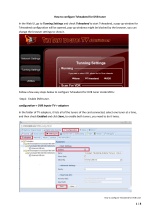
8.1 Software installation at PC
Download the software package from the homepage www.polytron.de (SATC12_Vxxx.zip) and unzip in the
directory of your choice (e.g. C:\ PXU 848).
The software can also be loaded from the enclosed USB stick.
8.1.1 Installation of the driver
Start the file Install_driver.cmd.
Follow the instructions on the screen.
Sometimes during first installation, the following dialogue can appear. This depends on the operating system. Carry
out the following instructions and select the fields as shown:
Then click the button Weiter to start the installation of the software.
No, not this time
Install software automatically

10
Then click the button Fertig stellen to finish the installation of the software.
The installation of the driver software is now finished.
8.1.2 Installation of the programming software
Install the software by starting the “Setup.exe“ program in the desired folder.
Follow the instructions on the screen.
Close the screen displays once the installation has ended.
After the installation of the programming software on the PC, the
PXU 848 X can be connected to the PC with the USB cable.
If this notice is displayed:
Continue the installation
The software was
installed for the following
hardware
USB

11
8.2 Programming of the device parameters
Start the program – SATC12 –
Click on Menu at the top left
The following menus are available:
Program Menu
Diagnostic
Firmware Update
Exit
Select Program Menu: All adjustments of the input and output parameters are carried out here. After calling up the
menu, the current parameters of all 8 channels will be displayed.
Via this menu, all settings of the input and output parameters can be done. The upper part of the menu shows the
device data such as type, serial number, hardware version and software versions for CPU (µC), CI, FPGA and MUX.
The right menu border contains the navigation buttons CHANNEL 1 - 4 and CHANNEL 5 - 8, which are used to call
the transponder/output specific data of the respective 4 channel strip. Via the button Multiplexing, the multiplexer
menu will be opened.

12
8.2.1 Input parameters SAT reception
DVB > Input signal TP > Transponder frequency
Choose the kind of signal
Enter transponder frequency
eingebe If DVB-T/T2 or
DVB-C is selected, please skip to
section 8.2.2.
Auto > LO frequency SR > Symbol rate
The required frequency will be set
automatically. The frequency can also
set to 09750 , 10600 or
OTHER frequency. Enter symbol rate
Search > Searching Tuner Locked
If the tuner locks on the
transponder, Tuner Locked
angezeigt. is displayed in the upper field.
After pressing the
Search button, the data is accepted
and the desired transponder is
set.

13
Receiving conditions (DVB-S/S2)
The quality of the input signal can be evaluated by using the bit error rate BER and the
signal-to-noise ratio SNR .
These depend on the quality of the reception conditions and the SAT signals.
Recommendation: Bit error rate BER should be ≤ 1e-6.
The table below shows required signal-to-noise ratio levels for varying FEC (forward error correction). The
corresponding values of the FEC (forward error correction) have to be taken from the tables of the satellite
operators. If e.g. the transponder has an FEC of 5/6, the SNR display must be at least 9 dB to guarantee good
signals.
FEC gut sehr gut
1/2 5-7dB 8-11dB
2/3 7-9dB 10-13dB
3/4 8-10dB 11-14dB
5/6 9-11dB 12-15dB
7/8 10-12dB 13-16dB

14
8.2.2 Input parameters for terrestrial range
TP > Frequency BW > Channel bandwidth
The kind of input signal
will be identified automatically.
Enter input frequency
. Select 7 or 8 MHz
PLP > Select service DVB-T2 Search > Searching
After pressing button
Search the data is accepted
and the desired channel is set.
If the tuner locks on the
Select PLP value transponder, Tuner Locked
0 (only for DVB-T2) is displayed in the upper field.
Reception conditions
The quality of the input signal can be evaluated by using the bit error rate BER and the
signal-to-noise ratio SNR .
These depend on the quality of the reception conditions and the signals.
Recommendation: Bit error rate BER should be ≤ 1e-6.
Required threshold value for the signal-to-noise ratio SNR is 26 dB for DVB-T and 32 dB
for DVB-T2.

15
8.2.3 Output parameters DVB-C
On Dual OFF > Output channel OP > Operating mode
If not all of the output channels are Normal > normal mode
to be assigned, each channel can
be switched off individually with OFF. Single > single carrier for level
Via Dual the dual channel function measurement with an
can be activated. analogue antenna
After the setting of all parameters measuring device
press the Set button. With this,
the adjusted parameters are accepted. Zero > digital channel with
Please repeat the steps for other content 0 (constant level
channels. without fluctuations)
F > Output frequency BW > Bandwidth
Frequency is freely selectable. Choose bandwidth depending on
It is recommended to use the output frequency between 7 MHz
appropriate TV standard channel and 8 MHz.
grid. The frequency of the channel
centre is set
(e.g. channel 21, 470…478 MHz,
channel centre setting 474 MHz).
QM > QAM mode SR > Symbol rate
Setting of the possible QAM mode up to 7.200 kiloSymbols/sec.
(16, 32, 64, 128, 256) depending on
the data rate of the input transponder. Is dependent on the selected QAM
Only possible QAM modes will be mode (used settings in cable net-
displayed. works: 256 QAM / SR 6.900).
Only the symbol rates that are
possible are accepted.
SP > Spectrum ATT > Output level
Normal > Normal mode The output level at the output is
90 dBµV and can be attenuated
Invers > Primary signal can be for each channel up to 12 dB in
inverted in its spectral position. 1dB steps.
Inversion is only necessary in
exceptional cases.
Notice: The connected DVB-C / QAM receivers must be programmed in accordance
to the parameters set in the headend.

16
8.2.4 Output parameters DVB-T
On Dual OFF > Output channel OP > Operating mode
If not all output channels are to be Normal > normal mode
assigned, each channel can be
switched off individually with OFF. Single > single carrier for level
Via Dual the dual channel function measurement with an
can be activated. analogue antenna
After the setting of all parameters, measuring device
press the Set button. With this,
the adjusted parameters are accepted. Zero > digital channel with
Please repeat the steps for other content 0 (constant level
channels. without fluctuations)
F > Output frequency BW > Bandwidth
Frequency is freely selectable. Choose bandwidth depending on
It is recommended to use the output frequency between 7 MHz
appropriate TV standard channel and 8 MHz.
grid. The frequency of the channel
centre is set
(e.g. channel 21, 470…478 MHz,
channel centre setting 474 MHz)
CR > Code rate GI > Guard interval
Setting of possible code rates Setting of possible guard intervals
(1/2, 2/3, 3/4, 5/6, 7/8). (1/4, 1/8, 1/16, 1/32)
CM > Carrier modulation QM > QAM mode
Display of possible
carrier - only 2k. QAM mode (16QAM, 32QAM,
64QAM).

17
SP > Spectrum ATT > Output attenuation
Normal > Normal mode The output level at the output is
90 dBµV and can be attenuated
Invers > Primary signal can be for each channel up to 12 dB in
inverted in its spectral position. 1 dB steps.
Inversion is only necessary in
exceptional cases.
Notice: The connected DVB-T receivers must be programmed in accordance to the
parameters set in the headend .
8.2.5 Dual channel function
If the data rate of the multiplexed transport stream is too high to accommodate the programs in a 7 or 8 MHz
channel, the dual channel function of the PXU 848 X can be activated. With this function, it is possible to split the
multiplexed transport stream to two output channels (DVB-T or DVB-C depending on version).
By selecting the menu item Dual, the dual channel function is activated. The activation can take place for the
channels 1 - 4. If the dual channel is activated in these channels, the output modulators of the channels 5 – 8 are
reserved for the dual channels.
The assignment is as follows:
1D = Dual channel activation of channel 1 Setting of the output parameters in channel 5
2D = Dual channel activation of channel 2 Setting of the output parameters in channel 6
3D = Dual channel activation of channel 3 Setting of the output parameters in channel 7
4D = Dual channel activation of channel 4 Setting of the output parameters in channel 8
By pressing the button Set the selection is accepted and the activation of the dual channel is displayed in the
corresponding channel.

18
Note: The input parameters for the channels 5 to 8 can also be programmed when the dual channel function is
activated and can be assigned to the outputs in the multiplexing menu
The assignment of the programs to the output channels of the dual channel can be done in the menu Multiplexing.
Depending on the activated dual channels, the corresponding dual output channels 1D, 2D, 3D and 4D to the output
channels 1, 2, 3 and 4 will be displayed for selection. If not all dual channels are active, the respective output
channels 5, 6, 7 or 8 can be used. The possible selection is displayed in the OUT column.
In order to decrypt the desired programs, a check mark must be placed in the column CI of the corresponding
program. This selection is only possible for channels 1 - 4 and dual channel 1D - 4D. Encrypted and free-to-air
services can be grouped together. By clicking on the button Save, all settings will be saved.
Under 8.3 “Multiplexing”, the procedure for the assignment of the programs to the output channels plus the
decryption and assignment of a new SID is described, please read if necessary!

19
8.3 Multiplexing function
To optimally utilise the capacities of the smart cards or/and to provide new program selections at the output of the
compact headend, the PXU 848 X offers a multiplexing function. Also certain services within a transponder can be
deleted at the output if they are not desired. Furthermore, encrypted services can be selected for decryption via this
function. If required, an LCN (Logical Channel Number) can be assigned for a program or an SID remapping can be
performed.
8.3.1 Multiplexing of services (programs)
Click on the Multiplexing button to open the following window. On the left side of the window, the list of available TV
services from the input is shown and on the right side, the available radio services. In the column IN, the input slot
(input tuner) of the respective program is displayed. At the bottom of the menu, a status indicator documents the
progress while saving the settings. If all data is saved in the system, in the status field Ready will be displayed.
By clicking on the button All OUTPUTS ON/OFF, the assignment of all the services to the outputs can be
deactivated/reactivated or, if necessary, specific input transponders only may be reactivated.
The allocation of a service/program is done via a click in the column OUT. A pop up menu will be opened, in which
by selecting the number 1 - 8, the assignment to the corresponding output takes place.
When outputs 1 - 4 are selected, the program can also be decrypted.
The assignment is as follows:
1 = output 1 via CI 1 5 = output 5
2 = output 2 via CI 2 6 = output 6
3 = output 3 via CI 3 7 = output 7
4 = output 4 via CI 4 8 = output 8

20
The lower section of the menu shows the data rate of the respective output.
If the data rate at the output is too high, in the field Rem. Bitrate OUTX, Overflow will be displayed. This means that
the data rate for the set parameters is too high and services have to be removed. The fields Rem. Bitrate OUTX are
marked in colors after checking:
Green: More than 10000 kSym of data rate capacity remaining.
Orange: Fewer than 10000 kSym capacity remaining.
Red: Fewer than 5000 kSym capacity remaining.
Overflow: The data volume for the setted DVB-C or DVB-T parameters are too high.
The verification of the data rate can be activated manually via clicking the button Check.
Press the button Save after finishing assignment of the desired programs to output channels and selection of the
programs to be decrypted. The configuration will be checked for data rate overflow and then saved.
By clicking the column headers LCN, Name, OUT or IN, sorting can be done in ascending order of numbers or
letters.
/