Page is loading ...

destaco.com
Automating Tomorrow™
WARNING: This is a controlled document. It is your responsibility to deliver this information to the end user of the
DESTACO CAMCO product. Failure to deliver this could result in your liability for injury to the user or damage to the
machine. For copies of this manual, call your Customer Service Representative at 1-800-645-5207.
TC1 Series Service Manual


Service Manual
TC1 TOOL CHANGER
1
Rev. A
24 Nov 2020
Contents
Product Specification .................................................................................................................................... 2
1. Product Safety ...................................................................................................................................... 3
2. Lubrication and Maintenance ................................................................................................................ 5
• Master Plate ...................................................................................................................................... 5
• Master Plate Pneumatic O-Ring Seal Replacement ......................................................................... 6
• Tool Plate .......................................................................................................................................... 7
• Accessories and Maintenance Kits ................................................................................................... 8
• Lubrication Faces .............................................................................................................................. 8
3. Electric Modules .................................................................................................................................... 9
• Electric Module Replacement .......................................................................................................... 9
• Electric Module O-Ring Seal Replacement .................................................................................... 10
• Electric Module Connector Pin Inspection ..................................................................................... 11
4. Troubleshooting Problems .................................................................................................................. 12
5. Document Revision History ................................................................................................................. 12
1
TC1
Service Manual

2
Service Manual
TC1 TOOL CHANGER
DOCUMENT SYMBOLS AND MARKINGS
SYMBOL
DEFINITION
Indicates a situation which, if not avoided, could result in damage to the
unit, equipment, or environment.
Indicates a hazardous
situation which, if not avoided, could result in minor
or moderate injury.
Electric shock hazard
Falling object hazard
Denotes the orientation with respect to gravity
Personal Protective Equipment (PPE)
The personal protective equipment (PPE) described below must be provided by the
unit owner and be worn by the responsible operating personnel when working with the
unit.
Wear safety shoes
Wear safety goggles
Product Specification
The TC1 series product ratings can be found in our catalog at www.destaco.com.
Operating the tool changer or accessories outside the parameters specified may result in damage to the
unit, attached equipment, facilities, and/or personal injury. It is the responsibility of the user to install and
operate the products within the parameters specified in the catalog.
G
2
TC1
Service Manual

Service Manual
TC1 TOOL CHANGER
3
Rev. A
24 Nov 2020
1. Product Safety
Recommended Decoupling Procedure
Before decoupling the tool plate, depressurize any connected pneumatic utilities. Failure to
do so may result in compressed air loss and/or damage to the O-Ring seals.
Whenever possible, decouple the tool plate from the master plate while it is in a horizontal
orientation (see Fig.1) so that the master plate can be removed in a horizontal direction rather than a vertical
direction. FAILURE TO FOLLOW THIS PROCEDURE MAY RESULT IN THE TOOL FREE FALLING DUE
TO GRAVITY AND MAY RESULT IN DAMAGE TO THE UNIT AND/OR PERSONAL INJURY.
Fig.1
Use additional caution if it is necessary to decouple the tool plate in the vertical orientation
(see Fig.2). DEPRESSING THE RELEASE BUTTON IN THE VERTICAL ORIENTATION MAY RESULT IN
THE TOOL FREE FALLING DUE TO GRAVITY AND MAY RESULT IN DAMAGE TO THE UNIT AND/OR
PERSONAL INJURY. Whenever possible, decouple the tool plate in the horizontal orientation (see Fig.1).
CUSTOMER
ROBOT
TOOL PLATE
MASTER
PLATE
G
TOOL PLATE
CUSTOMER
ROBOT
MASTER PLATE
G
Fig.2
3
TC1
Service Manual

4
Service Manual
TC1 TOOL CHANGER
Considerations for Operation in the Vertical Orientation
Use additional caution when operating the tool changer in the orientation shown in Fig.3,
such that gravity would cause the tool plate to free fall in the event of an inadvertent decoupling. Operating
in the orientation shown below may result in unintentional decoupling if the user overloads the tool changer
or in high vibration conditions. UNINTENTIONAL DECOUPLING MAY RESULT IN THE TOOL FREE
FALLING DUE TO GRAVITY AND MAY RESULT IN DAMAGE TO THE UNIT AND/OR PERSONAL
INJURY.
Fig.3
G
4
TC1
Service Manual

Service Manual
TC1 TOOL CHANGER
5
Rev. A
24 Nov 2020
2. Lubrication and Maintenance
Master Plate
Fig.5
TABLE 1
ITEM DESCRIPTION QTY
1 MASTER PLATE TC1-050M-XX 1
2 O-RING 2X5 4
3 M6 x 12MM DOWEL 1
4 M6 SHCS, 12MM LG PATCH LOCK 4
5 5MM HEX KEY WRENCH 1
5
TC1
Service Manual

6
Service Manual
TC1 TOOL CHANGER
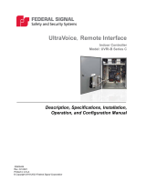
Master Plate Pneumatic O-Ring Seal Replacement
The O-Ring seals ensure leak-proof air utility pass through when the master and tool plates are coupled.
The seals should be inspected periodically for any cuts, damage, or abrasion. If any damage has
occurred to the O-Rings, they must be replaced. The O-Rings are replaced by the following procedure:
1. Remove all pneumatic and electric power sources from the tool changer before servicing
the master plate seals. Servicing or maintaining the tool changer without isolating it from pneumatic and
electric power sources may result in electric shock and personal injury. WHILE SERVICE OR
MAINTENANCE WORK SHOULD NEVER BE DONE WITH THE TOOL CHANGER CONNECTED TO
A POWER SOURCE, by way of example, electric shock may result where maintenance or service work
involves the use of metallic tools or other electrical conducting materials, particularly when addressing
the O-Rings.
2. A seal replacement kit (Part No. SLKT-480) is available, see Table.3 on Page 8.
3. Carefully remove the O-Rings without damaging the tool changer surface or O-Ring grooves.
4. Place the new O-Rings in the O-Ring grooves of the master body and press until they are fully seated
(see Fig.4). Lubricate lightly with oil after assembly.
Note: The tool plate does not contain pneumatic O-Ring seals.
Fig.4
O-RING
ELECTRICAL MODULE
MASTER PLATE
6
TC1
Service Manual

Service Manual
TC1 TOOL CHANGER
7
Rev. A
24 Nov 2020
Tool Plate
Fig.6
TABLE 2
ITEM DESCRIPTION QTY
1 TOOL PLATE TC1-050T-XX 1
2 M5 x 8MM DOWEL 2
3 M3 x 6MM DOWEL 2
4 M3 SHCS, 10MM LG PATCH LOCK 4
5 M5 SHCS, 8MM LG PATCH LOCK 4
6 5MM HEX KEY WRENCH 1
7 4MM HEX KEY WRENCH 1
7
TC1
Service Manual

8
Service Manual
TC1 TOOL CHANGER
Accessories and Maintenance Kits
TABLE 3
PART NUMBER DESCRIPTION
SLKT-480 SEAL KIT
TC1-E01M-C01 8 PIN M8 SOCKET ELECTRICAL PASS-THRU MASTER MODULE
TC1-E01T-C01 8 PIN M8 PLUG ELECTRICAL PASS-THRU TOOL MODULE
TC1-E01T-P01 PNP MAGNETO RESISTIVE 4MM SENSING MODULE
TC1-E01T-N01 NPN MAGNETO RESISTIVE 4MM SENSING MODULE
TC1-050H-01 TOOL HOLDER – M6 MOUNTING
Lubrication Faces
1. Master Plate
Lightly lubricate the ways and O-Rings on the master plate as shown with oil as needed.
• TC1-050M-XX
Fig.7
2. Tool Plate
Lightly lubricate the ways on the tool plate as shown with oil as needed.
• TC1-050T-XX
Fig.8
1
2
3
1
3
2
6
4
7
5
8
TC1
Service Manual

Service Manual
TC1 TOOL CHANGER
9
Rev. A
24 Nov 2020
3. Electric Modules
Electric power and signal modules are available in various configurations. See Table 4 for compatibility
with master and tool plates.
Electric Module Replacement
1. Remove all pneumatic and electric power sources from the tool changer before servicing
the electric modules. Servicing or maintaining the tool changer without isolating it from pneumatic and
electric power sources may result in electric shock and personal injury.
2. Remove the existing electric module by disconnecting the electrical connector and unscrewing the M3
screws using 2.5mm hex key wrench (see Fig.9 or Fig.10).
3. Place the new electric module in the same position, apply Loctite 242, 243, or equivalent to the screws
and tighten to 0.9 Nm using the 2.5mm hex key wrench. Reconnect the electrical connector.
Fig.9
TABLE 4
ITEM PART NUMBER DESCRIPTION COMPATIBILITY
1 TC1-E01M-C01 8 PIN M8 SOCKET ELECTRICAL PASS-THRU MASTER MODULE TC1-050M-XX
2 TC1-E01T-C01 8 PIN M8 PLUG ELECTRICAL PASS-THRU TOOL MODULE
TC1-050T-XX
3 TC1-E01T-P01 PNP MAGNETO RESISTIVE 4MM SENSING MODULE
3 TC1-E01T-N01 NPN MAGNETO RESISTIVE 4MM SENSING MODULE
M3 FLAT HEAD
SCREW
MASTER ELECTRICAL
MODULE
MASTER
PLATE
2.5mm HEX KEY WRENCH
0.9Nm
THREAD LOCKER
242/243
9
TC1
Service Manual

10
Service Manual
TC1 TOOL CHANGER
Fig.10
Electric Module O-Ring Seal Replacement
The O-Ring seal in the master electric module protects the electrical interface between the master and
tool plates. The seal needs to be checked periodically for any cuts, damage, or abrasion and must be
replaced if damaged.
1. Remove all pneumatic and electric power sources from the tool changer before servicing
the master module seal. Servicing or maintaining the tool changer without isolating it from pneumatic
and electric power sources may result in electric shock and personal injury. WHILE SERVICE OR
MAINTENANCE WORK SHOULD NEVER BE DONE WITH THE TOOL CHANGER CONNECTED TO
A POWER SOURCE, by way of example, electric shock may result where maintenance or service work
involves the use of metallic tools or other electrical conducting materials, particularly when addressing
the O-Rings.
2. A seal replacement kit (Part No. SLKT-480) is available, refer Table.3 on Page 8.
3. Carefully remove the O-Ring and any residual glue without damaging the module surface or O-Ring
grooves.
4. Add a small amount of glue to the seal groove of the master module being careful not to contaminate the
electrical interface.
5. Place the new O-Ring in the seal groove of the electrical interface of the master module and press until
it is fully seated (see Fig.11). Carefully remove any glue that squeezes out without contaminating the
electrical contacts. No lubrication is required.
Note: Electric module of tool plate does not contain an O-Ring seal.
M3 FLAT HEAD SCREW
TOOL ELECTRICAL
MODULE
TOOL PLATE
2.5mm HEX KEY WRENCH
0.9 Nm
THREAD LOCKER
242/243
10
TC1
Service Manual

Service Manual
TC1 TOOL CHANGER
11
Rev. A
24 Nov 2020
Fig.11
Electric Module Connector Pin Inspection
1. Check the electric module periodically for any debris or darkened pins (see Fig.12 or Fig.13).
2. If there is any contamination, use a nylon brush to clean the connector pins and socket.
3. If there is any damage such as bent, broken, corroded, or missing pins the module must be replaced.
Fig.12
Fig.13
MASTER ELECTRICAL
MODULE
O-RING
MASTER PLATE
O-RING
MASTER ELECTRICAL
MODULE
TOOL PLATE
TOOL ELECTRICAL
MODULE
CONNECTOR PIN
MASTER ELECTRICAL
MODULE
MASTER PLATE
CONNECTOR SOCKET
11
TC1
Service Manual

12
Service Manual
TC1 TOOL CHANGER
4. Troubleshooting Problems
Problem
Possible Cause
Tool changer doesn’t lock or unlock
• Spring damage
• Burrs in the latch or tool plate notch
Air leakage
• O-Ring damage
• One or more O-Rings missing
• Contamination of O-Rings
• Pneumatic fittings loose or damaged
Electrical module not working
• Debris present
• Connector pin damaged
• Tool plate not coupled properly
• Cable pinched/damaged
Electrical module contaminated
• O-Ring seal damaged
• Excess humidity
• Environmental contaminants
5. Document Revision History
TABLE 5
REVISION ECN DESCRIPTION DATE BY
A - INITIAL RELEASE 17-11-2020 SB
12
TC1
Service Manual

13
TC1
Service Manual

© Copyright, 2021 DESTACO. All rights for layout, photos and text rest with the publisher
DESTACO. All photomechanical or other reproductions only with our express permission.
All sales are based on our terms and conditions of sale, delivery and payment. TC_TC1-SM_0121
Global Locations
NORTH AMERICA
Corporate Headquarters
Auburn Hills, Michigan
Toll Free: 1.888.DESTACO
Marketing: [email protected]
Global Technology Center
Auburn Hills, Michigan
Tel: 1.248.836.6700
Customer Service: [email protected]
Mt. Juliet, Tennessee
Tel: 1.888.DESTACO
Customer Service: [email protected]
Wheeling, Illinois
Tel: 1.800.645.5207
Customer Service: [email protected]
Red Wing, Minnesota (Central Research Laboratories)
Tel: 651.385.2142
Customer Service: [email protected]
ASIA
Thailand
Tel: +66-2-326-0812
Customer Service: [email protected]
China
Tel: +86-21-6081-2888
Customer Service: [email protected]
India
Tel: +91-80-41123421-426
Customer Service: [email protected]
EUROPE
Germany
Tel: +49-6171-705-0
Customer Service: [email protected]
France
Tel: +33-4-73545001
Customer Service: [email protected]
Great Britain
Tel: +44-1902-797980
Customer Service: [email protected]
Spain
Tel: +34-936361680
Customer Service: [email protected]
Netherlands
Tel: +31-297285332
Customer Service: [email protected]
Spain
Netherlands
Great Britain
France
India
Thailand
China
Mt. Juliet, TN USA
Auburn Hills, MI USA
Germany
Red Wing, MN USA
Wheeling, IL USA
/