Page is loading ...

1
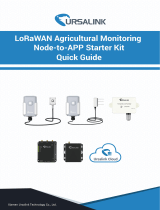
UG87 LoRaWAN Gateway
Quick Start Guide
Ursalink Technology Co., Ltd.

www.ursalink.com
2
Welcome
Thank you for choosing Ursalink UG87 LoRaWAN Gateway.
This guide teaches you how to install the UG87 and how to log in the web GUI to configure the device. Once
you complete the installation, refer to the Ursalink UG87 User Guide for instructions on how to perform
configurations on the device.
Related Documents
This Quick Start Guide only explains the installation of Ursalink UG87 LoRaWAN Gateway. For more
functionality and advanced settings, please refer to the relevant documents as below.
Document
Description
Ursalink UG87 Datasheet
Datasheet for the Ursalink UG87 LoRaWAN Gateway.
Ursalink UG87 User Guide
Users can refer to the guide for instruction on how to log in the
web GUI, and how to configure all the settings.
The related documents are available on Ursalink website: http://www.ursalink.com.
Declaration of Conformity
UG87 is in conformity with the essential requirements and other relevant provisions of the CE, FCC, and
RoHS.
For assistance, please contact
Ursalink technical support:
Email: helpdesk@ursalink.com
Tel: 86-592-5023060
Fax: 86-592-5023065

Ursalink UG87 Quick Start Guide
www.ursalink.com
3
Revision History
Date
Doc Version
Description
Sept. 9, 2019
V1.1
Initial version
Oct. 18, 2019
V1.2
1. Add 16 channels description;
2. Change antenna location.
Nov. 29, 2019
V1.3
Delete AC/DC power supply, add PoE injector
Apr. 4, 2020
V1.4
1. Reset button definition change;
2. Add back AC/DC power supply;
3. Default IP change from 192.168.1.1 to 192.168.23.150;
4. Web GUI interface change (based on 80.0.0.62);
5. Add bulk import LoRaWAN devices.

Ursalink UG87 Quick Start Guide
www.ursalink.com
4
Contents
1. Packing List.......................................................................................................................................................5
2. Hardware Introduction.....................................................................................................................................6
2.1 Overview................................................................................................................................................ 6
2.2 Dimensions.............................................................................................................................................7
2.3 LED Indicators.........................................................................................................................................7
2.4 Reset Button...........................................................................................................................................8
2.5 Ethernet Port Indicator.......................................................................................................................... 8
3. Hardware Installation.......................................................................................................................................9
3.1 SIM Card Installation.............................................................................................................................. 9
3.2 Antenna Installation...............................................................................................................................9
3.3 Power Supply........................................................................................................................................10
3.3.1 PoE Power Supply......................................................................................................................10
3.3.1.1 Connect UG87 to PoE Switch......................................................................................... 10
3.3.1.2 Connect UG87 to PoE Injector....................................................................................... 10
3.3.2 AC/DC Power Supply (Optional)................................................................................................11
3.4 Mount Gateway................................................................................................................................... 12
3.4.1 Wall Mounting...........................................................................................................................12
3.4.2 Pole Mounting ( Hose clamp)....................................................................................................13
3.4.3 Pole Mounting (U-bolt)............................................................................................................. 14
4.Access the Web GUI of UG87..........................................................................................................................15
4.1 PC Configuration.................................................................................................................................. 15
4.2 Log in the Web GUI of UG87................................................................................................................16
5.Connect UG87 to the Netowork..................................................................................................................... 18
5.1 Configure the WAN Connection...........................................................................................................18
5.2 Configure the Cellular Connection.......................................................................................................18
5.3 Configure the Wi-Fi Connection...........................................................................................................20
6.Packet Forwarder Configuration..................................................................................................................... 23
7.Network Server Configuration........................................................................................................................ 25
7.1 Connect UG87 to Ursalink Cloud......................................................................................................... 25
7.2 Connect UG87 to Other Platform........................................................................................................ 26

Ursalink UG87 Quick Start Guide
www.ursalink.com
5
1. Packing List
Before you begin to install the UG87 LoRaWAN Gateway, please check the package contents to verify that
you have received the items below.
1 × WiFi Antenna
(WiFi Version Only)
1 × Wall Mounting Kit
2 × Pole Mounting Kit
Screws
1 × Warranty Card
1 × PoE Injector
1 × Power cable
(AC/ DC Version Only)
1 × Ethernet Cable
(Optional)
Optional Installation Accessories
1 × Pole Mount A + 2 × U-Bolt
1 × Pole Mount B + 2 × U-Bolt
Screws
If any of the above items is missing or damaged, please contact your Ursalink sales
representative.
1 × UG87
1 × Cellular Antenna
1 × LoRa Antenna
(2 × LoRa Antennas for
16-channel model)
1 × GPS Antenna
+
+

Ursalink UG87 Quick Start Guide
www.ursalink.com
6
2. Hardware Introduction
2.1 Overview
A. Front Panel
B. Rear Panel
C. Top & Bottom View
1LoRa2 Antenna (only for 16-channel model)
2GPS Antenna
3LTE Antenna
4LoRa1 Antenna
5Vent Plug
6Power Connector
7Ethernet Port (PoE)
8LED&SIM Area
9Wi-Fi Antenna
LED&SIM Area
10 PWR: Power Indicator
11 SYS: System Indicator
12 SIM Card Slot
13 L2: Cellular Indicator
14 RST: Reset Button
15 L1: LoRa Indicator

Ursalink UG87 Quick Start Guide
www.ursalink.com
7
2.2 Dimensions (mm)
2.3 LED Indicators
LED
Indication
Status
Description
PWR
Power Status
On
The power is switched on
Off
The power is switched off
SYS
System Status
Green Light
Static: Start-up
Blinking slowly: the system is running properly
Off
The system goes wrong
L1
LoRa Status
Green Light
Package Forwarder mode is running well.
Off
Package Forwarder mode is running off.
L2
SIM Card Status
Off
SIM1 or SIM2 is registering or fails to register (or
there are no SIM cards inserted)
Green Light
Blink Slowly: SIM1 has been registered and is ready
for dial-up
Blink Rapidly: SIM1 has been registered and is
dialing up now
Static: SIM1 or SIM2 has been registered and dialed
up successfully
Orange
Light
Blink Slowly: SIM2 has been registered and is ready
for dial-up
Blink Rapidly: SIM2 has been registered and is
dialing up now
Static: SIM2 has been registered and dialed up
successfully

Ursalink UG87 Quick Start Guide
www.ursalink.com
8
2.4 Reset Button
Function
Description
SYS LED
Action
Reset
Blinking
Press and hold the reset button for more than 5 seconds.
Static Green →
Rapidly Blinking
Release the button and wait.
Off → Blinking
The gateway resets to factory default.
2.5 Ethernet Port Indicator
Indicator
Status
Description
Link Indicator (Orange)
On
Connected
Blinking
Transmitting data
Off
Disconnected
Rate
Indicator (Green)
On
1000 Mbps mode
Off
100 Mbps mode

Ursalink UG87 Quick Start Guide
www.ursalink.com
9
3. Hardware Installation
Environmental Requirements
- Power Input: PoE (IEEE 802.3af standard) (Option: 100-240 VAC/9-48VDC)
- Power Consumption: Typical 4.9 W, Max 6.5 W (8 channels)
Typical 6 W, Max 8.2 W (16 channels)
- Ingress Protection: IP67
- Operating Temperature: -40°C to 70°C (-40°F -158°F)
- Relative Humidity: 0% to 95% (non-condensing) at 25°C/77°F
3.1 SIM Card Installation
Remove the cover of the SIM card slot with a wrench and insert the SIM card.
Note: Check the triangle icon of the SIM card slot.
3.2 Antenna Installation
A. Remove the protective caps from the antenna connectors.
B. Connect the antenna to the corresponding antenna connector by holding the metal part of the antenna
and rotating it clockwise.
Note: Each antenna is labeled as cellular, GPS, WLAN or LoRa.

Ursalink UG87 Quick Start Guide
www.ursalink.com
10
3.3 Power Supply
3.3.1 PoE Power Supply
Ethernet cable of UG87 device side should be installed first, or PoE devices or gateway may be damaged.
3.3.1.1 Connect UG87 to PoE Switch
Connect UG87 Ethernet port to a PoE switch via Ethernet cable. PoE switch must meet IEEE 802.3 af
standard.
3.3.1.2 Connect UG87 to PoE Injector
Connect UG87 Ethernet port to a PoE injector via Ethernet cable. PoE injector must meet IEEE 802.3 af
standard.

Ursalink UG87 Quick Start Guide
www.ursalink.com
11
3.3.2 AC/DC Power Supply (Optional)
A. Locate the power port marked POWER on the left side of the enclosure and remove the protective cap to
find the connection pins.
B. Connect a power supply cable to the power port, and rotate it clockwise.
Type
PIN
Color
Description
VAC
1
Brown
L (VIN+)
2
Black
GND
3
Blue
N (VIN-)
Type
PIN
Color
Description
VDC
1
Brown
V+
2
Black
GND

Ursalink UG87 Quick Start Guide
www.ursalink.com
12
3.4 Mount Gateway
The gateway can be mounted to a wall or a pole.
3.4.1 Wall Mounting
Make sure you have mounting bracket, bracket mounting screws, wall plugs, wall mounting screws and
other required tools.
1. Before you start, make sure that your SIM card has been inserted, your antennas have been attached and
that all cables have been disconnected from your enclosure.
2. Mount the enclosure to the mounting bracket with the bracket mounting screws.
3. Align the mounting bracket horizontally to the desired position on the wall, use a marker pen to mark
four mounting holes on the wall, and then remove the mounting bracket from the wall.
Note: The connecting lines of adjacent points are at right angles.
4. Drill four holes with a depth of 32 mm by using your drill with a 6 mm drill bit on the positions you
marked previously on the wall.
5. Insert four wall plugs into the holes respectively.
6. Mount the mounting bracket horizontally to the wall by fixing the wall mounting screws into the wall
plugs.
Note: Place the power port on the button when installing.
7. Reconnect the cables.

Ursalink UG87 Quick Start Guide
www.ursalink.com
13
3.4.2 Pole Mounting ( Hose clamp)
Make sure you have mounting bracket, bracket mounting screws, hose clamp and other required tools.
1. Before you start, make sure that your SIM card has been inserted, your antennas have been attached and
that all cables have been disconnected from your enclosure.
2. Mount the enclosure to the mounting bracket with the bracket mounting screws.
3.Loosen the hose clamp by turning the locking mechanism counter-clockwise.
4.Straighten out the hose clamp and slide it through the rectangular holes in the mounting bracket, wrap the
hose clamp around the pole.
5.Use a screwdriver to tighten the locking mechanism by turning it clockwise.
6.Reconnect the cables.

Ursalink UG87 Quick Start Guide
www.ursalink.com
14
3.4.3 Pole Mounting (U-bolt)
Note: Pole mounting (U-bolt) is optional.
Make sure you have mounting bracket, bracket mounting screws, hose clamp and other required tools.
1. Before you start, make sure your SIM card has been inserted, your antennas have been attached and that
all cables have been disconnected from your enclosure.
2. Mount the enclosure to the mounting bracket with the bracket mounting screws.
3. Wrap the U-bolt around the pole and mount the bracket with the mounting screws.
4. Reconnect the cables.

Ursalink UG87 Quick Start Guide
www.ursalink.com
15
4.Access the Web GUI of UG87
Ursalink UG87 provides web-based configuration interface for management. If this is the first time you
configure the gateway, please use the default settings below:
IP Address: 192.168.23.150
Username: admin
Password: password
4.1 PC Configuration
Please connect PC to Ethernet port of UG87 directly and configure a static IP address manually. The
following steps are based on Windows 10 operating system for your reference.
③Click “Ethernet” (May have different names). ④Click “Properties”.
①Click “Search Box” to search “Control Panel” on the
Windows 10 taskbar.
②Click “Control Panel” to open it, and then click
“View network status and tasks”.

Ursalink UG87 Quick Start Guide
www.ursalink.com
16
(Note: Remember to click “OK” to finish configuration.)
4.2 Log in the Web GUI of UG87
A. Open a Web browser on your PC (Chrome and IE are recommended), type in the IP address, and press
Enter on your keyboard.
B. Enter the username and password, click “Login”.
If you enter the username or password incorrectly more than 5 times, the login page will be locked
for 10 minutes.
C. When you log in with the default username and password, you will be asked to change password. It’s
suggested that you change the password for the sake of security. Click “Cancel” button if you want to modify
it later.
⑤Double Click “Internet Protocol
Version 4 (TCP/IPv4)” to
configure IP address and DNS
server.
⑥ Click “Use the following IP
address” to assign a static IP
manually within the same subnet of
the gateway.

Ursalink UG87 Quick Start Guide
www.ursalink.com
17
D. After you log in the Web GUI, you can view system information and perform configuration of the gateway.

Ursalink UG87 Quick Start Guide
www.ursalink.com
18
5.Connect UG87 to the Netowork
This chapter explains how to connect the gateway to network via WAN connection, cellular or Wi-Fi.
5.1 Configure the WAN Connection
A. Go to “Network”→ “Interface” → “Port” page to select the connection type and configure WAN
information.
B. Click “Save&Apply” for configuration to take effect.
C. Connect Ethernet port of gateway to network devices like router or modem.
D. Log in the web GUI via the newly assigned IP address and go to “Status”→ “Network” to check Ethernet
port status.
5.2 Configure the Cellular Connection
Take inserting SIM card into SIM1 slot as an example; please refer to the following detailed operations.
A. Go to “Network” → “Interface” → “Cellular” → “Cellular Setting” page to configure the cellular info.

Ursalink UG87 Quick Start Guide
www.ursalink.com
19
B. Enable SIM1.
C. Choose relevant network type. “Auto”, “4G Only”, “3G Only” and “2G Only” are optional.
D. Click “Save” and “Apply” for configuration to take effect.

Ursalink UG87 Quick Start Guide
www.ursalink.com
20
UG87 has two cellular interfaces named SIM1 & SIM2. Only one cellular interface is active at one time. If
both cellular interfaces are enabled, SIM1 interface takes precedence by default.
E. Go to “Status” → “Cellular” page to view the status of the cellular connection. If it shows “Connected”, it
means SIM1 has dialed up successfully. On the other hand, you can check the status of L2 indicator. If it
keeps on green light statically, it means SIM has dialed up successfully.
5.3 Configure the Wi-Fi Connection
A. Go to “Network” → “Interface” → “WLAN” and select “Client” mode.
B. Click “Scan” to search for Wi-Fi access point. Select the available one and click “Join Network”.
/