Page is loading ...

Questions, problems, missing parts? Before returning to your retailer, call our customer
service department at 1-866-994-4148, 8 a.m. - 6 p.m., EST, Monday - Thursday,
8 a.m. - 5 p.m., EST, Friday.
ITEM #1332862
EASY FIT INSTALL
VENTILATION FAN
WITH LED LIGHT
MODEL #7115-03
Français p. 13
Español p. 25
AB1740
ATTACH YOUR RECEIPT HERE
Serial Number
_______________
Purchase Date
______________
TM
READ AND SAVE THESE INSTRUCTIONS

2
TABLE OF CONTENTS
PRODUCT SPECIFICATIONS
Product Specications ........................................................................................................................2
Package Contents ..............................................................................................................................3
Safety Information ..............................................................................................................................3
Preparation .........................................................................................................................................4
New Construction Assembly Instructions ...........................................................................................6
Existing Construction Assembly Instructions ...................................................................................... 8
Care and Maintenance .....................................................................................................................12
Troubleshooting ................................................................................................................................ 12
Warranty ...........................................................................................................................................13
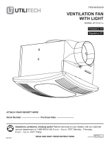
TYPICAL INSTALLATION
SPECIFICATIONS SPECIFICATIONS
Airow: 100 CFM Sound output: 1.5 Sones
120 V, 60 Hz Power consumption: 30 W
Duct diameter: 4 in. Weight: 8.2 lbs.

3
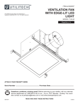
PACKAGE CONTENTS
PART DESCRIPTION QUANTITY
A Fan body 1
B Grille 1
C Duct connector 1
A
C
B
SAFETY INFORMATION
READ AND SAVE THESE INSTRUCTIONS
Please read and understand this entire manual before attempting to assemble, operate or install
the product.
1. Always disconnect the power supply prior to servicing the fan, motor or junction box.
2. Follow all local building, safety and electrical codes, as well as NEC (National Electrical Code) and
OSHA (Occupational Safety and Health Act).
3. Electric service supply must be 120 volts, 60 hertz.
4. This product must properly connect to the grounding conductor of the supply circuit.
5. Do not bend or kink the power wires.
6. Do not use this fan with any solid state control device, such as a remote control, or certain timers.
Mechanical timers are not solid state devices.
7. Do not install in a ceiling with insulation greater than R40.
8. Duct work should be installed in a straight line with minimal bends.
9. Duct work size must be the same size as the discharge and should not be reduced. Reducing the
duct size may increase fan noise.

4
SAFETY INFORMATION
WARNING
TO REDUCE THE RISK OF FIRE, ELECTRIC SHOCK, OR INJURY TO PERSONS, OBSERVE THE
FOLLOWING:
1. Use this unit in the manner intended by the manufacturer. If you have any questions, please call
customer service.
2. Before servicing or cleaning unit, switch power off at service panel and lock the service
disconnecting means to prevent power from being switched on accidentally. When the service
disconnecting means cannot be locked, securely fasten a prominent warning device, such as a tag,
to the service panel.
3. Installation work and electrical wiring must be done by a qualied person(s) in accordance with all
applicable codes and standards, including re-rated construction.
4. Sufcient air is needed for proper combustion and exhausting of gases through the ue (chimney)
of fuel burning equipment to prevent backdrafting. Follow the heating equipment manufacturer’s
guideline and safety standards such as those published by the National Fire Protection Association
(NFPA), and the American Society for Heating, Refrigeration and Air Conditioning Engineers
(ASHRAE) and local code authorities.
5. When cutting or drilling into the wall or ceiling, do not damage electrical wiring and other hidden
utilities.
6. Ducted fans must always be vented to the outdoors.
7. If this unit is to be installed over a tub or shower, it must be marked as appropriate for the application
and be connected to a GFCI (Ground Fault Circuit Interrupter) – protected branch circuit.
CAUTION
1. For general ventilating use only. Do not use to exhaust hazardous or explosive materials and vapors.
2. Not for use in cooking areas.
3. To reduce the risk of injury to persons, install the fan at least 8.2 feet (2.5m) above the oor.
PREPARATION
Before beginning assembly of product, make sure all parts are present. Compare parts with package
contents list. If any part is missing or damaged, do not attempt to assemble the product.
Estimated Assembly Time: 60 minutes
Tools Required for Assembly (not included): Hammer, Flathead Screwdriver, Wood Screws, Nails, Duct
Tape, Phillips Screwdriver, Utility Knife
Helpful Tools (not included): Electric Drill, Drill Bits
WARNING: Turn off electricity at breaker box before beginning installation.
Carefully remove unit from carton.
Check area above installation location to be sure that wiring can run to the planned location and that
duct work can be run and the area is sufcient for proper ventilation.
Inspect duct work and wiring before proceeding with installation.
Before installation, provide inspection and future maintenance access at a location that will not interfere
with installation work.
You may need the help of a second person to install this fan: one person on the attic side and one on
the room side.

5
PREPARATION
Note: Installations may vary depending on how the previous bath fan was installed. Supplies necessary
for the installation of your bath fan are not all included; however, most are available at your local
home improvement or hardware store.
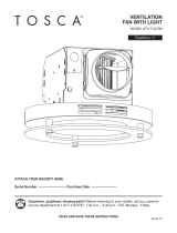
DIMENSION REQUIREMENTS
Ceiling
Opening (L)
Ceiling
Opening (W)
Ceiling
Opening (H)
7.5 in. 7.25 in. 5.75 in.
WIRING DIAGRAM

6
Joist
NEW CONSTRUCTION ASSEMBLY INSTRUCTIONS
BEFORE INSTALLATION – Turn off power source.
Review all safety precautions.
1. Attach the duct connector (C) to the fan housing (A).
2. Remove the wiring box cover (2.1) from the fan
housing (A). Remove the wiring knockout (2.2) from
the wiring box cover (2.1) with a athead screwdriver
(not included).
3. Place the fan housing (A) next to a ceiling joist. The
fan housing should be level and perpendicular to the
joist.
2
3
1
A
C
2.1
7.12.2
A
A

7
4 in. duct
Ceiling
Duct tape
or clamp
Wire nut
(not included)
House
wires
Product
wires
NEW CONSTRUCTION ASSEMBLY INSTRUCTIONS
4. Mount the fan housing (A) to the ceiling joist using
wood screws (4.1) (not included) where indicated.
5. Pull the house wires through the wire box cover hole.
Secure 120 V AC house wiring from the wall switch
to the fan as shown in the wiring diagram on page 5.
14 AWG is the smallest conductor that should be used
for branch-circuit wiring.
Carefully push the connected wires back into the
wiring box housing. Reattach the wiring box cover.
CAUTION: If the electrical wires do not match the
colors listed, you must determine what each house
wire represents before connecting. You may need to
consult an electrical contractor to determine safely.
6. Install a circular 4 in. duct (6.1) (not included) and
secure it with duct tape or clamps (neither included).
Finish ceiling work. The ceiling hole should be aligned
with the edge of the fan housing (A).
Ceiling Joist
4
5
6
A
A
4.1
4.1
A
6.1

8
NEW CONSTRUCTION ASSEMBLY INSTRUCTIONS
EXISTING CONSTRUCTION ASSEMBLY INSTRUCTIONS
7. For the LED light connection, plug in the connector
(7.1) from the grille (B) into the fan housing (A) as
shown.
Pinch the mounting springs (7.2) on the grille (B) and
insert them into the narrow rectangular slots (7.3)
inside the fan housing (A). Push the grille (B) up
toward the ceiling.
BEFORE INSTALLATION – Turn off power source. Review
all safety precautions. Remove old fan.
1. Measure the opening to ensure it is large enough
to accommodate the new fan housing (A)
(7.5 in. x 7.25 in.).
If this fan is not replacing an old fan, be sure to cut a
7.5 in. x 7.25 in. opening for the fan housing (A).
MAKE SURE THE 7.25 IN. SIDE OF THE OPENING
IS FLUSH WITH THE JOIST FOR INSTALLATION
FROM BELOW.
2. Attach the duct connector (C) to the fan housing (A).
4
5
6
7
8
9
1
0
1
1
1
7.50"
7.25
"
1
7.1
7.1
7.2
7.2
A
7.3
B
7
2
A
C

9
EXISTING CONSTRUCTION ASSEMBLY INSTRUCTIONS
3. Remove the three screws (3.1) that hold the motor
assembly (3.2) in place. Remove the fan motor
assembly (3.2) from the fan housing (A). Unplug the
fan power unit (3.3).
4. Remove the wiring box cover (4.1) from the fan
housing (A). Remove the wiring knockout (4.2) from
the wiring box cover (4.1) with a athead screwdriver
(not included).
5. Pull the house wires through the wire box cover hole.
Secure 120 V AC house wiring from the wall switch
to the fan as shown in the wiring diagram on page 5.
14 AWG is the smallest conductor that should be used
for branch-circuit wiring.
Carefully push the connected wires back into the wiring
box housing. Reattach the wiring box cover.
CAUTION: If the electrical wires do not match the
colors listed, you must determine what each house wire
represents before connecting. You may need to consult
an electrical contractor to determine safely.
3
4
3.1
3.2
A
4.1
4.2
A
3.3
5
Wire nut
(not included)
House
wires
Product
wires

10
EXISTING CONSTRUCTION ASSEMBLY INSTRUCTIONS
6. Install a circular 4 in. duct (6.1) (not included) and
secure it with duct tape or clamps (neither included).
Finish ceiling work. The ceiling hole should be
aligned with the edge of the fan housing (A).
7. Insert the fan housing (A) through the existing hole in
the ceiling. The fan housing (A) should be level and
perpendicular to the joist.
8. Mount the fan housing (A) to the ceiling joist using
wood screws (8.1) (not included) where indicated
by arrows inside the fan housing.
4 in. duct
Ceiling
Duct tape
or clamp
6
7
A
6.1
A
8
Ceiling Joist
A
8.1

11
EXISTING CONSTRUCTION ASSEMBLY INSTRUCTIONS
9. Plug back in the power unit (9.1). Replace motor
assembly (9.2) back into fan housing (A) using the
three screws (9.3) removed in step 3.
10. For the LED light connection, plug in the connector
(10.1) from the grille (B) into the fan housing (A) as
shown.
Pinch the mounting springs (10.2) on the grille (B)
and insert them into the narrow rectangular slots
(10.3) inside the fan housing (A). Push the grille (B)
up toward the ceiling.
10.1
10.2
A
10.3
B
10.1
10.2
10
9
9.3
9.2
A
9.1
CARE AND MAINTENANCE
WARNING: Disconnect power supply before servicing. See SAFETY INFORMATION before proceeding.
Routine maintenance should be done at least once a year.
• Wash grille with mild soap and water, dry with a cloth.
• Remove excess dirt and dust from the fan housing with a vacuum cleaner.
• Do not use solvents, thinner or harsh chemicals for cleaning the fan.
• Do not allow water to enter the motor.
• Do not immerse resin parts in water over 140º F.

12
LIMITED 5-YEAR WARRANTY
If this product fails due to a defect in materials or workmanship at any time during the rst FIVE years of ownership, the
manufacturer will replace it free of charge, postage-paid at their option. This warranty does not cover products that have
been abused, altered, damaged, misused, cut or worn. This warranty does not cover use in commercial applications. Use
only manufacturer-supplied genuine warranty repair replacement parts to repair this fan. Use of non-genuine repair parts
will void your warranty. The manufacturer DISCLAIMS all other implied or express warranties including all warranties of
merchantability and/or tness for a particular purpose. As some states do not allow exclusions or limitations on an implied
warranty, the above exclusions and limitations may not apply. This warranty gives you specic legal rights, and you may
have other rights that vary from state to state.
This warranty is limited to the replacement of defective parts only. Labor charges and/or damage incurred during installation,
repair, replacement as well as incidental and consequential damages connected with the above are excluded. Any damage
to this product as a result of neglect, misuse, accident, imporper installation or use other than the purpose SHALL VOID
THIS WARRANTY.
Shipping costs for return product as part of a claim on the warranty must be paid for by the customer.
Inquiries regarding warranty claims can be directed to 1-866-994-4148, 8 a.m. - 6 p.m., EST, Monday - Thursday,
8 a.m. - 5 p.m., EST, Friday.
TROUBLESHOOTING
PROBLEM POSSIBLE CAUSE CORRECTIVE ACTION
The fan seems
louder than it should
CFM too great
Be sure the CFM rating on the fan
matches the size of your room
Damper not working properly or
damaged
Check damper to ensure it is opening
and closing properly. If the damper
has become damaged, please call
Customer Service
Bend in duct too close to fan discharge
Be sure you do not have any sharp
bends in duct closer than 18 in. to the
fan discharge
Fan discharge reduced to t smaller
duct
Use recommended size ducting to
reduce fan noise
Fan body not securely attached
Be sure the fan is securely attached
to your ceiling joists
The fan is not
clearing the room
Insufcient intake airow within room
Be sure a door or window is slightly
ajar or opened to allow airow. The
fan is not able to draw air out of the
room without enough airow to draw
from
Insufcient CFM
Be sure the CFM rating on the fan
matches the requirements for your
room size
NOTE: Using a tissue is not an
accurate method for determining if
the fan is operating properly. If the
fan clears steam from the room
within approximately 15 minutes of
completing your shower, then the
fan is operating properly
Printed in China
/